EP0862103A2 - Anzeigevorrichtung - Google Patents
Anzeigevorrichtung Download PDFInfo
- Publication number
- EP0862103A2 EP0862103A2 EP98101903A EP98101903A EP0862103A2 EP 0862103 A2 EP0862103 A2 EP 0862103A2 EP 98101903 A EP98101903 A EP 98101903A EP 98101903 A EP98101903 A EP 98101903A EP 0862103 A2 EP0862103 A2 EP 0862103A2
- Authority
- EP
- European Patent Office
- Prior art keywords
- stick
- base
- keyboard
- computer
- cursor
- Prior art date
- Legal status (The legal status is an assumption and is not a legal conclusion. Google has not performed a legal analysis and makes no representation as to the accuracy of the status listed.)
- Withdrawn
Links
- 230000003750 conditioning effect Effects 0.000 claims description 4
- 230000008878 coupling Effects 0.000 claims description 2
- 238000010168 coupling process Methods 0.000 claims description 2
- 238000005859 coupling reaction Methods 0.000 claims description 2
- 238000010079 rubber tapping Methods 0.000 abstract description 4
- 230000004913 activation Effects 0.000 abstract description 2
- 239000000463 material Substances 0.000 description 15
- 210000003811 finger Anatomy 0.000 description 7
- 230000008859 change Effects 0.000 description 5
- 239000010408 film Substances 0.000 description 4
- 239000002184 metal Substances 0.000 description 4
- 229910052751 metal Inorganic materials 0.000 description 4
- 239000004033 plastic Substances 0.000 description 4
- 229920003023 plastic Polymers 0.000 description 4
- 239000000758 substrate Substances 0.000 description 4
- 230000008901 benefit Effects 0.000 description 3
- 229910010293 ceramic material Inorganic materials 0.000 description 3
- 238000013461 design Methods 0.000 description 3
- 238000000034 method Methods 0.000 description 3
- 229910000679 solder Inorganic materials 0.000 description 3
- 239000004593 Epoxy Substances 0.000 description 2
- 238000005452 bending Methods 0.000 description 2
- 238000013479 data entry Methods 0.000 description 2
- 238000003825 pressing Methods 0.000 description 2
- 230000004044 response Effects 0.000 description 2
- HUWSZNZAROKDRZ-RRLWZMAJSA-N (3r,4r)-3-azaniumyl-5-[[(2s,3r)-1-[(2s)-2,3-dicarboxypyrrolidin-1-yl]-3-methyl-1-oxopentan-2-yl]amino]-5-oxo-4-sulfanylpentane-1-sulfonate Chemical compound OS(=O)(=O)CC[C@@H](N)[C@@H](S)C(=O)N[C@@H]([C@H](C)CC)C(=O)N1CCC(C(O)=O)[C@H]1C(O)=O HUWSZNZAROKDRZ-RRLWZMAJSA-N 0.000 description 1
- PNEYBMLMFCGWSK-UHFFFAOYSA-N Alumina Chemical compound [O-2].[O-2].[O-2].[Al+3].[Al+3] PNEYBMLMFCGWSK-UHFFFAOYSA-N 0.000 description 1
- 241000282326 Felis catus Species 0.000 description 1
- 239000004952 Polyamide Substances 0.000 description 1
- 239000004830 Super Glue Substances 0.000 description 1
- 230000001133 acceleration Effects 0.000 description 1
- 230000003213 activating effect Effects 0.000 description 1
- 239000000853 adhesive Substances 0.000 description 1
- 230000001070 adhesive effect Effects 0.000 description 1
- 230000000712 assembly Effects 0.000 description 1
- 238000000429 assembly Methods 0.000 description 1
- 239000000919 ceramic Substances 0.000 description 1
- 238000001514 detection method Methods 0.000 description 1
- 238000007599 discharging Methods 0.000 description 1
- 230000009977 dual effect Effects 0.000 description 1
- 230000000694 effects Effects 0.000 description 1
- 230000005611 electricity Effects 0.000 description 1
- 239000003822 epoxy resin Substances 0.000 description 1
- FGBJXOREULPLGL-UHFFFAOYSA-N ethyl cyanoacrylate Chemical compound CCOC(=O)C(=C)C#N FGBJXOREULPLGL-UHFFFAOYSA-N 0.000 description 1
- 239000011521 glass Substances 0.000 description 1
- 210000004247 hand Anatomy 0.000 description 1
- LQBJWKCYZGMFEV-UHFFFAOYSA-N lead tin Chemical compound [Sn].[Pb] LQBJWKCYZGMFEV-UHFFFAOYSA-N 0.000 description 1
- 238000004519 manufacturing process Methods 0.000 description 1
- 238000005259 measurement Methods 0.000 description 1
- 150000002739 metals Chemical class 0.000 description 1
- 229920002647 polyamide Polymers 0.000 description 1
- 239000004417 polycarbonate Substances 0.000 description 1
- 229920000515 polycarbonate Polymers 0.000 description 1
- 229920000647 polyepoxide Polymers 0.000 description 1
- 229920001721 polyimide Polymers 0.000 description 1
- 230000001681 protective effect Effects 0.000 description 1
- 238000012552 review Methods 0.000 description 1
- 238000012216 screening Methods 0.000 description 1
- 230000011664 signaling Effects 0.000 description 1
- 230000007727 signaling mechanism Effects 0.000 description 1
- 238000004544 sputter deposition Methods 0.000 description 1
- 230000003068 static effect Effects 0.000 description 1
- 239000010409 thin film Substances 0.000 description 1
- 210000003813 thumb Anatomy 0.000 description 1
- 230000007704 transition Effects 0.000 description 1
Images


Classifications
-
- G—PHYSICS
- G05—CONTROLLING; REGULATING
- G05G—CONTROL DEVICES OR SYSTEMS INSOFAR AS CHARACTERISED BY MECHANICAL FEATURES ONLY
- G05G9/00—Manually-actuated control mechanisms provided with one single controlling member co-operating with two or more controlled members, e.g. selectively, simultaneously
- G05G9/02—Manually-actuated control mechanisms provided with one single controlling member co-operating with two or more controlled members, e.g. selectively, simultaneously the controlling member being movable in different independent ways, movement in each individual way actuating one controlled member only
- G05G9/04—Manually-actuated control mechanisms provided with one single controlling member co-operating with two or more controlled members, e.g. selectively, simultaneously the controlling member being movable in different independent ways, movement in each individual way actuating one controlled member only in which movement in two or more ways can occur simultaneously
- G05G9/047—Manually-actuated control mechanisms provided with one single controlling member co-operating with two or more controlled members, e.g. selectively, simultaneously the controlling member being movable in different independent ways, movement in each individual way actuating one controlled member only in which movement in two or more ways can occur simultaneously the controlling member being movable by hand about orthogonal axes, e.g. joysticks
-
- G—PHYSICS
- G05—CONTROLLING; REGULATING
- G05G—CONTROL DEVICES OR SYSTEMS INSOFAR AS CHARACTERISED BY MECHANICAL FEATURES ONLY
- G05G9/00—Manually-actuated control mechanisms provided with one single controlling member co-operating with two or more controlled members, e.g. selectively, simultaneously
- G05G9/02—Manually-actuated control mechanisms provided with one single controlling member co-operating with two or more controlled members, e.g. selectively, simultaneously the controlling member being movable in different independent ways, movement in each individual way actuating one controlled member only
- G05G9/04—Manually-actuated control mechanisms provided with one single controlling member co-operating with two or more controlled members, e.g. selectively, simultaneously the controlling member being movable in different independent ways, movement in each individual way actuating one controlled member only in which movement in two or more ways can occur simultaneously
- G05G9/047—Manually-actuated control mechanisms provided with one single controlling member co-operating with two or more controlled members, e.g. selectively, simultaneously the controlling member being movable in different independent ways, movement in each individual way actuating one controlled member only in which movement in two or more ways can occur simultaneously the controlling member being movable by hand about orthogonal axes, e.g. joysticks
- G05G2009/0474—Manually-actuated control mechanisms provided with one single controlling member co-operating with two or more controlled members, e.g. selectively, simultaneously the controlling member being movable in different independent ways, movement in each individual way actuating one controlled member only in which movement in two or more ways can occur simultaneously the controlling member being movable by hand about orthogonal axes, e.g. joysticks characterised by means converting mechanical movement into electric signals
-
- G—PHYSICS
- G05—CONTROLLING; REGULATING
- G05G—CONTROL DEVICES OR SYSTEMS INSOFAR AS CHARACTERISED BY MECHANICAL FEATURES ONLY
- G05G9/00—Manually-actuated control mechanisms provided with one single controlling member co-operating with two or more controlled members, e.g. selectively, simultaneously
- G05G9/02—Manually-actuated control mechanisms provided with one single controlling member co-operating with two or more controlled members, e.g. selectively, simultaneously the controlling member being movable in different independent ways, movement in each individual way actuating one controlled member only
- G05G9/04—Manually-actuated control mechanisms provided with one single controlling member co-operating with two or more controlled members, e.g. selectively, simultaneously the controlling member being movable in different independent ways, movement in each individual way actuating one controlled member only in which movement in two or more ways can occur simultaneously
- G05G9/047—Manually-actuated control mechanisms provided with one single controlling member co-operating with two or more controlled members, e.g. selectively, simultaneously the controlling member being movable in different independent ways, movement in each individual way actuating one controlled member only in which movement in two or more ways can occur simultaneously the controlling member being movable by hand about orthogonal axes, e.g. joysticks
- G05G2009/04777—Manually-actuated control mechanisms provided with one single controlling member co-operating with two or more controlled members, e.g. selectively, simultaneously the controlling member being movable in different independent ways, movement in each individual way actuating one controlled member only in which movement in two or more ways can occur simultaneously the controlling member being movable by hand about orthogonal axes, e.g. joysticks with additional push or pull action on the handle
-
- Y—GENERAL TAGGING OF NEW TECHNOLOGICAL DEVELOPMENTS; GENERAL TAGGING OF CROSS-SECTIONAL TECHNOLOGIES SPANNING OVER SEVERAL SECTIONS OF THE IPC; TECHNICAL SUBJECTS COVERED BY FORMER USPC CROSS-REFERENCE ART COLLECTIONS [XRACs] AND DIGESTS
- Y10—TECHNICAL SUBJECTS COVERED BY FORMER USPC
- Y10T—TECHNICAL SUBJECTS COVERED BY FORMER US CLASSIFICATION
- Y10T74/00—Machine element or mechanism
- Y10T74/20—Control lever and linkage systems
- Y10T74/20012—Multiple controlled elements
- Y10T74/20201—Control moves in two planes
Definitions
- This invention generally relates to a pointing device for controlling the positioning, movement and operation of a cursor on a display screen. Specifically, there is a pointing stick that both directs a cursor and acts as the activation button far selecting items on the display screen by tapping on the pointing stick instead of clicking on a mouse button. Additionally, there is a pointing stick that is ESD (electrostatic discharge) insensitive.
- ESD electrostatic discharge
- Various devices are well known for controlling cursor movement over a computer display screen of a computer and for signaling a choice of computer command identified by the position of the cursor on the display screen menu.
- One such device is a "mouse" which has a ball on its underside rolled over a horizontal surface, with the x- and y-axis components of movement being sensed and transmitted through a connecting cable to a serial input port of the computer.
- the signal to the computer is varied by the amount and direction of movement of the mouse ball, and causes the cursor on the display screen to have a corresponding movement.
- One or two "mouse” or “click” buttons located on the top of the mouse at the forward end permit the computer operator to enter a selection or other command to the computer (the command typically being shown by the position of the cursor on a displayed menu) upon pressing one or the other or both buttons, depending upon (he software associated with the device,
- a selection or other command to the computer the command typically being shown by the position of the cursor on a displayed menu
- buttons depending upon (he software associated with the device.
- Such a device which is separate from the computer console and keyboard and requires a connection to a computer port, requires a flat, horizontal surface, and for operation of the mouse, the computer operator must completely remove one hand from the computer keyboard.
- cursor controlling and signaling mechanism is a "joystick" which like the mouse is completely separated from the computer console and keyboard
- the joystick is typically an elongated stick that extends upwardly from a base connected to the computer console by means of a cable.
- the joystick is operated by tilting the upstanding stick in various directions to cause the cursor or other display element to move in a direction and usually at a speed corresponding to the direction and pressure exerted on the stick by the computer operator.
- the operation of a joystick frequently requires that both hands be removed from the computer keyboard, one hand to hold the base while the other manipulates the joystick.
- a “click” button is usually located on the joystick.
- cursor controlling device is a "trackball.”
- This device which in essence is an inverted mouse, includes a rotatable ball mounted within a housing. The ball is rotated by a finger, thumb or palm of the computer operator, and the x- and y-components of movement are sensed and input into the computer to cause corresponding movement of the cursor across the display screen. "Mouse” or “click” buttons are usually located on the trackball housing, although with some models the selection signal is input by pressing the "enter” key on the standard keyboard.
- This type of pointing device has been found useful with portable computers because it can be temporarily affixed to one side of the computer case for manipulation by one hand of the computer operator.
- trackball devices can be removably attached to the computer case, they still require attachment before use and removal after use. It is also noted that some trackballs are built into the computer keyboard. Nonetheless, these trackballs require a separate set of "click" buttons for selection of items on the display monitor.
- Seffernick forces are those forces that are applied to a supporting structure, a keyboard for example, that are translated to the pointing stick. For example, typing on a keyboard can generate seffernick forces. In that case, the pointing stick is so sensitive that a user would be activating the pointing stick operation unintentionally. The sensitive electronics on the pointing stick would sense the deformation of the keyboard support surfaces and translate that into deformation of its own support surface and mistakenly generate control signals. Thus, seffernick forces are those forces that are translated from a support structure through the body of the pointing stick and to the electronic components of the pointing stick sufficient to generate unintentional control signals..
- ESD electrostatic discharge
- a further feature of the invention is to provide a pointing stick assembly using resistor based strain gages mounted on the sides of the shaft of the pointing stick.
- the strain gages are for sensing when either the stick or base is being bent. Upon bending, strain is crested on the resistor based strain gages.
- the strain gages are coupled to circuitry that will produce signals in response to the strain on the gages. The resulting signals are used to either control the movement of the cursor around the display screen, or to do what is commonly called "clicking" a mouse button for selection of items or dragging of items on the display screen.
- a further feature of the invention is to provide a device that has a pointing stick extending through the base so that the side mounted strain gages extend through the bendable base. Thus, when the stick is pushed downward along the z-axis, the base will exert pressure on all strain gages.
- a further feature of the invention is to provide an easy method or design for coupling the electrical traces located on the flexible cable to the resistor based strain gages.
- An additional feature of the invention is to provide a mountable pointing stick that is protected from seffernick forces.
- a protective housing that isolates the post assembly and is not mechanically fixed to the post assembly. Additionally, the housing does not deform the base and electrical parts of the pointing stick when the housing itself is being deformed to some degree or being jarred by seffernick forces.
- a post base and electrical trace film that are bonded together forming the electro-mechanical working portion of the invention.
- a housing component of the invention which is integrally mounted to a keyboard base, and protects the post assembly from stresses associated with mounting to the keyboard.
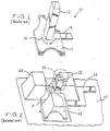
- the pointing stick 10 that can be used to control the movement of a curser on a computer screen (not shown).
- the pointing stick 10 is made up of a stick 12 (or shaft), a substrate 14 for supporting the stick 12 (also referred to as a shaft or post), and a cavity 16 formed in the base 14 for placement of a flexible cable 18 that is electrically connected to four strain gages (not shown) located on the sides of the stick 12.
- the stick may be made of alumina ceramic material.
- the cable 18 may be made of polyamide material containing electrical traces thereon.
- the pointing stick 10 is typically positioned on the supporting base 20 and between the B, G and H keys 22 of a typing keyboard.
- the pointing stick has a rubber-like cap 24 positioned over the top of stick 12 to increase the ease of operation.
- the cap is designed to enable the operator to control the cursor with a single finger positioned on top of it and pushing in desired cursor direction.
- the finger pressure causes strain in the stick that is sensed by the sensitive gages (not shown).
- the base 14, made of epoxy glass, FR4, or molded polycarbonate material, to name a few, will have some impact upon the strain gages because of the increased flexibility of the base around the gages.
- FIG. 3 there is a perspective view of the preferred embodiment of the invention.
- pointing stick 10 having a post assembly 311.
- the post assembly 311 is made up of the ceramic post 12, a plastic base 312 for mounting the post therein, and the flexible cable 18 for routing signals from the post 12 to signal conditioning circuitry (not shown).
- the post assembly components are fixedly attached to each other to form a unitary body.
- the post 12 has strain gages 30 (electrical circuit) mounted thereon, and a plastic cap 24 positioned over the post for, use by a keyboard user to direct the movement of a cursor on a computer display.
- the cover includes a mounting tab 313 for attaching the cover to a bracket 316.
- the bracket 316 serves as a base for mounting the whole pointing stick assembly 10 onto a keyboard 20 by attaching support pads 317 thereto.
- the base 312 has a collar 318 that protrudes from the cover 314, and a second section 320 that fits under cover 314.
- Bracket 316 has holes 319 therein for inserting tabs 313 therethrough, which are thereby bent upon being inserted into the position illustrated.
- Bracket 316 is typically mounted upon a structure 321, like a keyboard, via pads 317.
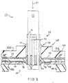
- Strain gages 30 are mounted on the sides of the stick 12 and are made of pressure sensitive strips 32, for electrically changing the resistance of the material in response to the amount of strain applied thereto, a conductive contact bridge 34 for electrically connecting the two strips 32, and conductive contact pads 36 for making electrical contact to signal conditioning electronic circuitry (not shown) via flexible cable 18.
- a suitable material for the cable 18 is a polyimide film, also known as a printed flex cables made by Fujikura America.
- the cable 18 has electrical traces 44 and input/output (I/O) pads 46 mounted between the two insulative layers 18'.
- the insulative film layers insulate the traces from the bracket 316.
- the stick 12 extends through hole 38 in a z-axis direction 39, and is held in place by an adhesive bond epoxy 40.
- an adhesive bond epoxy 40 for example, a cyanoacrylate adhesive material is also suitable for bonding.
- Cable 18 is positioned within cavity 16.
- Contact pads 36 are bonded to I/O pads 46 by any suitable bond material 50, like tin-lead solder. It is noted that only the post assembly is bonded together and it is not fixedly attached to the housing 315.
- the pointing stick 10 can be assembled as follows: The first step usually involves either the screening of resistive thick film or the sputtering of resistive thin film material on the sides of stick 12. The screened on material forms the strain gages 30. The second step often involves the placement of the stick 12 into the substrate or plastic base 312 (or base). Thereafter, usually flexible cable 18 is attached to connect the strain gages 30 to signal conditioning circuitry (not shown). Next, the solder material may be placed around the stick 12 to attach all eight I/O pads 46 to all eight contact pads 36, two on each side of the stick 12. Next, a certain amount of bonding material 40 may be applied onto the cable to secure it to the base 312. Finally, the whole assembly is cured to harden the bonding materials. Finally, the now completed post assembly 311 is placed onto the bracket 316 and the cover 314 is thereby attached by tabs 313, thus holding the post assembly therein.
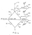
- FIG. 6 there is an electrical schematic of a bridge circuit incorporating the strain sensitive elements.
- this circuit is an example of how the z-axis pointing stick can be arranged to interface with the electronics (not shown);
- the strain sensitive resistors 32 on opposing sides of the stick 12 are configured in two half bridge circuits, resistors 32 Y+ and 32 Y- form a first half bridge, and resistors 32 X+ and 32 X-form the second half bridge.
- a fixed resistor 110 is connected between the supply voltage 112 of the system and node 114.
- the X, Y, and Z OUT outputs, 116, 118, and 120 respectively, are amplified by the three differential amplifiers 160, 161, and 162. Each amplifier has a variable reference voltage input.
- the X and Y axis outputs 116 and 118 are developed when an X or Y directional force is applied to the stick 12. For example, when a force is applied in the X direction, the X- and X+ strain sensitive resistors change resistance in opposite directions and cause an output change. The same is true for the Y-axis.
- a Z-axis output is developed when a Z-axis force is applied to the top of the stick 12. Force in the Z-axis causes all resistors 32 on the stick 12 to change in a negative direction. This change lowers the total impedance of the two half bridges. The lower bridge impedance causes a voltage change in the Z output 120 since the series resistor 110 is fixed.
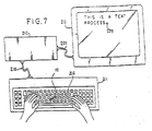
- FIG. 7 there is shown a keyboard operated computer system.
- the system includes a keyboard 211 implemented by this invention and connected to a computer 212.
- the data entry from the keyboard 211 is displayed on a computer display or monitor 213 during the normal course of operation of an application program.
- the keyboard has a layout of keys 216 that is an industry standard.
- the keyboard is shown to have an output cable 218 coupled to the computer 212.
- the computer is coupled to the monitor via connecting cable 206.
- a cursor 209 is displayed on the computer monitor 213.
- the pointing stick 10 is located in the middle of the keyboard 211.
- strain gages are devises that sense the amount and of applied pressure placed upon the pointing stick. The sensed pressure creates electrical output signals used to direct the cursor on a display device.
- the side mounted strain gages enables control of both the directions of the cursor movement and the selection of items on the display device by tapping the pointing stick like the clicking or a mouse button.
- the base 312 may have some flexure in a downward direction during the application of tapping force. Specifically, the flexing of the base 312 will cause some force to be applied to the sensor from the top portion of the walls of the hole 38.
- strain gages may be made of thick films piezo-resistive material, which are applied using known screen techniques.
- the pointing stick 10 is capable of now performing selection and dragging of icons on a monitor in addition to double clicking for selection of an item.
- the user would hold down the pointing stick 10 while exerting additional force in the X-Y plane for controlling the direction of the icon being dragged. All of these functions are now capable of being performed with a single finger while the remaining fingers are inactively located on a homerow of the keyboard.
- the homerow being the keys marked "a, s, d, f, j, k, l, and ;" as typically referred to in typing manuals.
- the housing 315 and the post assembly 311 which are not permanently fixed to each other.
- the advantage of having two separate loose parts is that the housing protects the post assembly from seffernick forces resulting from keyboard usage. In other words, a keyboard user could pound upon the keyboard and cause some deformation of the housing 315, but the force sensitive electronics on the post assembly 311 would not be deformed or sense the seffernick forces enough to generate spurious signals.
- the housing 315 and assembly 311 are tightly positioned to each other, there is enough room for the assembly to move independent of the housing. This independent movement between these two parts provides for the insensitivity to seffernick forces.
- collar 318 serves to create and focus the strain onto the strain gages located on the flexible post 12. Thus, when a z-axis force 39 is applied thereto, collar 318 will press against the post 12 generally on all four sides.
- mounting pabs 317 lift or isolate the remaining portion of the pointing stick off of the supporting structure 321, like is a keyboard 20.
- the combination of the lifting of the main portion of the pointing stick 10 off of the keyboard and the loose fitting of the post assembly 311 within the housing 315 also server to stop the effect of seffernick forces upon the post assembly.
- both the cover and bracket may be made of an electrically conducive material, preferably metal.
- the housing When the housing is made of metal it will act as a low impedance path to ground for any potential electrostatic discharge (ESD) events.
- ESD electrostatic discharge
- the metal housing 315 will protect the electrical circuitry, via. the strain gages, from any potential ESD.
- the pointing stick 10 would have to be coupled to a ground potential.
- pointing stick 12 and substrate 312 out of any suitable material, like ceramic material, plastics, epoxy resin, or metals etc.
- bonding compound 40 is illustrated to be placed between the substrate 312 and the stick 12, it may not be required when the hole 38 fits securely around the stick 12. This is equally true for material 50 if the flexible cable 18 fits securely around stick 12, in which only a small amount of solder may be needed to enhance electrical contact therebetween.
- the embodiment discusses the use of strain gages on all four sides of the stick 12, it is contemplated to use only two sides of the stick 12 for sensing only either the positive or negative strain on the bending of the stick for creating the resulting control signals.
- the base 312 is illustrated in FIG. 5 as having a large step between the collar 318 and the second portion 320, it is contemplated to have many designs for the transition. For example, it is possible to have a ramping, or even to have the second section 320 to be the same as the collar 318.
- the flexible cable 18 separates the base 312 from contact with the bracket 316, it is contemplated to form a groove in base 312 to fit a smaller sized cable around the post 12 so that the base 312 would then act as a supporting surface to contact bracket 316.
Landscapes
- Physics & Mathematics (AREA)
- General Physics & Mathematics (AREA)
- Engineering & Computer Science (AREA)
- Automation & Control Theory (AREA)
- Position Input By Displaying (AREA)
Applications Claiming Priority (2)
| Application Number | Priority Date | Filing Date | Title |
|---|---|---|---|
| US08/794,703 US20020018048A1 (en) | 1997-02-04 | 1997-02-04 | Z-axis pointing stick with esd protection |
| US794703 | 1997-02-04 |
Publications (2)
| Publication Number | Publication Date |
|---|---|
| EP0862103A2 true EP0862103A2 (de) | 1998-09-02 |
| EP0862103A3 EP0862103A3 (de) | 1999-11-03 |
Family
ID=25163409
Family Applications (1)
| Application Number | Title | Priority Date | Filing Date |
|---|---|---|---|
| EP98101903A Withdrawn EP0862103A3 (de) | 1997-02-04 | 1998-02-04 | Anzeigevorrichtung |
Country Status (4)
| Country | Link |
|---|---|
| US (2) | US20020018048A1 (de) |
| EP (1) | EP0862103A3 (de) |
| CA (1) | CA2228720A1 (de) |
| TW (1) | TW390989B (de) |
Cited By (2)
| Publication number | Priority date | Publication date | Assignee | Title |
|---|---|---|---|---|
| EP0992872A2 (de) | 1998-10-07 | 2000-04-12 | CTS Corporation | Anzeigevorrichtung und Verfahren zu ihrer Herstellung |
| EP0986022A3 (de) * | 1998-09-09 | 2000-06-28 | CTS Corporation | Steuerknüppel mit integrierender Steuerungsschaltung |
Families Citing this family (34)
| Publication number | Priority date | Publication date | Assignee | Title |
|---|---|---|---|---|
| GB2335024A (en) * | 1998-03-06 | 1999-09-08 | Ibm | Joystick for portable computer system |
| JP2000003637A (ja) * | 1998-04-15 | 2000-01-07 | Seimitsu Kogyo Kk | 起倒スティック式指示装置 |
| US6137475A (en) * | 1998-05-21 | 2000-10-24 | Cts Corporation | Pointing stick having an interposer connecting layer |
| TW468128B (en) * | 1999-01-08 | 2001-12-11 | Acer Peripherals Inc | Pointing stick and its manufacturing method |
| JP2000207102A (ja) * | 1999-01-18 | 2000-07-28 | Alps Electric Co Ltd | キ―ボ―ド装置 |
| US6331849B1 (en) * | 1999-02-25 | 2001-12-18 | Cts Corporation | Integrated surface-mount pointing device |
| US6304247B1 (en) * | 1999-03-02 | 2001-10-16 | Cts Corporation | Piezoelectric stick pointing device |
| US6295050B1 (en) * | 1999-03-18 | 2001-09-25 | International Business Machines Corporation | Joy stick pointing device to control the movement of a graphical element on a computer display monitor |
| TW449713B (en) * | 1999-08-27 | 2001-08-11 | Darfon Electronics Corp | A pointing stick device that enables to increase the sensitivity of vertical direction |
| US6323840B1 (en) * | 1999-09-17 | 2001-11-27 | Cts Corporation | Surface-mount pointing device |
| JP2001331272A (ja) * | 2000-05-24 | 2001-11-30 | Alps Electric Co Ltd | 文字入力装置 |
| US6697049B2 (en) * | 2000-05-31 | 2004-02-24 | Darfon Electronics Corp. | Pointing stick with a rectangular-shaped hollow structure |
| USD448378S1 (en) | 2000-10-16 | 2001-09-25 | U.S. Philips Corporation | Universal keyboard |
| US20030066739A1 (en) * | 2001-07-02 | 2003-04-10 | Rickenbach Roger D. | Controller with tactile feedback |
| US6624805B2 (en) * | 2001-07-06 | 2003-09-23 | Behavior Tech Computer Corporation | Cursor controller |
| USD464654S1 (en) | 2001-07-27 | 2002-10-22 | Pelco | Joystick |
| US6892597B2 (en) | 2001-07-27 | 2005-05-17 | Pelco | Joystick |
| US6788291B2 (en) * | 2001-11-06 | 2004-09-07 | Cts Corporation | Integrated surface-mount pointing device |
| US7297896B2 (en) * | 2002-11-21 | 2007-11-20 | Hadco Santa Clara, Inc. | Laser trimming of resistors |
| US7170487B2 (en) * | 2003-01-20 | 2007-01-30 | Murata Manufacturing Co., Ltd. | Pointing device and method of producing the same |
| US6839965B2 (en) * | 2003-02-06 | 2005-01-11 | R-Tec Corporation | Method of manufacturing a resistor connector |
| US7567419B2 (en) * | 2005-06-10 | 2009-07-28 | Kyocera Wireless Corp. | Apparatus, system, and method for electrostatic discharge protection |
| KR100765261B1 (ko) * | 2006-07-11 | 2007-10-09 | 삼성전자주식회사 | 표시장치 |
| US7451664B1 (en) | 2007-09-28 | 2008-11-18 | Honeywell Interntional Inc. | User interface force sensor system |
| JP2009163881A (ja) * | 2007-12-27 | 2009-07-23 | Toshiba Corp | 電子機器 |
| US20090239665A1 (en) * | 2007-12-31 | 2009-09-24 | Michael Minuto | Brandable thumbstick cover for game controllers |
| US8136421B2 (en) * | 2008-01-10 | 2012-03-20 | Honeywell International Inc. | Gimbal assembly including flexible substrate wiring harnesses |
| JP2010020502A (ja) * | 2008-07-10 | 2010-01-28 | Alps Electric Co Ltd | ポインティングデバイス |
| JP5024358B2 (ja) * | 2009-01-08 | 2012-09-12 | 株式会社日本自動車部品総合研究所 | 作用力検出装置 |
| USD635591S1 (en) * | 2009-04-01 | 2011-04-05 | Abb Ab | Joystick |
| US8803803B2 (en) * | 2011-01-25 | 2014-08-12 | Sony Corporation | Operation member provided in electronic device, and electronic device |
| JP6104577B2 (ja) * | 2012-11-29 | 2017-03-29 | ミネベアミツミ株式会社 | ポインティングスティック |
| WO2017180726A1 (en) * | 2016-04-12 | 2017-10-19 | Mark Slotta | Control stick cap with retention features |
| CN107329597B (zh) * | 2017-08-23 | 2023-09-29 | 湖南中力皓电子科技有限公司 | 一种加固指点杆 |
Citations (11)
| Publication number | Priority date | Publication date | Assignee | Title |
|---|---|---|---|---|
| US4680577A (en) | 1983-11-28 | 1987-07-14 | Tektronix, Inc. | Multipurpose cursor control keyswitch |
| US4876524A (en) | 1985-07-19 | 1989-10-24 | Jenkins Richard L | Six-axis joystick control |
| US4905523A (en) | 1987-04-24 | 1990-03-06 | Wacoh Corporation | Force detector and moment detector using resistance element |
| US4967605A (en) | 1987-04-24 | 1990-11-06 | Wacoh Corporation | Detector for force and acceleration using resistance element |
| US5263375A (en) | 1987-09-18 | 1993-11-23 | Wacoh Corporation | Contact detector using resistance elements and its application |
| US5325081A (en) | 1993-06-14 | 1994-06-28 | Miraco, Inc. | Supported strain gauge and joy stick assembly and method of making |
| US5407285A (en) | 1990-07-24 | 1995-04-18 | Franz; Patrick J. | Pointing stick in a computer keyboard for cursor control |
| USRE35016E (en) | 1988-11-15 | 1995-08-15 | Sri International, Inc. | Three-axis force measurement stylus |
| US5473347A (en) | 1994-03-16 | 1995-12-05 | Gateway 2000 | Integrated pointing and signaling device |
| US5489900A (en) | 1994-06-03 | 1996-02-06 | International Business Machines Corporation | Force sensitive transducer for use in a computer keyboard |
| US5521596A (en) | 1990-11-29 | 1996-05-28 | Lexmark International, Inc. | Analog input device located in the primary typing area of a keyboard |
Family Cites Families (7)
| Publication number | Priority date | Publication date | Assignee | Title |
|---|---|---|---|---|
| US35016A (en) * | 1862-04-22 | Improvement in carriage-brakes | ||
| US5231386A (en) * | 1990-07-24 | 1993-07-27 | Home Row, Inc. | Keyswitch-integrated pointing assembly |
| WO1995008167A1 (en) * | 1993-09-13 | 1995-03-23 | Asher David J | Joystick with membrane sensor |
| US5659334A (en) * | 1993-12-15 | 1997-08-19 | Interlink Electronics, Inc. | Force-sensing pointing device |
| GB2290600A (en) * | 1994-06-22 | 1996-01-03 | Penny & Giles Electronic Compo | Joystick assembly |
| US5594618A (en) * | 1995-02-06 | 1997-01-14 | Compaq Computer Corporation | Collapsible pointing stick apparatus for a portable computer |
| US5882206A (en) * | 1995-03-29 | 1999-03-16 | Gillio; Robert G. | Virtual surgery system |
-
1997
- 1997-02-04 US US08/794,703 patent/US20020018048A1/en not_active Abandoned
-
1998
- 1998-02-04 EP EP98101903A patent/EP0862103A3/de not_active Withdrawn
- 1998-02-04 CA CA002228720A patent/CA2228720A1/en not_active Abandoned
- 1998-02-11 TW TW087101830A patent/TW390989B/zh not_active IP Right Cessation
- 1998-09-09 US US09/149,713 patent/US6002388A/en not_active Expired - Lifetime
Patent Citations (12)
| Publication number | Priority date | Publication date | Assignee | Title |
|---|---|---|---|---|
| US4680577A (en) | 1983-11-28 | 1987-07-14 | Tektronix, Inc. | Multipurpose cursor control keyswitch |
| US4876524A (en) | 1985-07-19 | 1989-10-24 | Jenkins Richard L | Six-axis joystick control |
| US4905523A (en) | 1987-04-24 | 1990-03-06 | Wacoh Corporation | Force detector and moment detector using resistance element |
| US4967605A (en) | 1987-04-24 | 1990-11-06 | Wacoh Corporation | Detector for force and acceleration using resistance element |
| US4969366A (en) | 1987-04-24 | 1990-11-13 | Wacoh Corporation | Moment detector using resistance element |
| US5263375A (en) | 1987-09-18 | 1993-11-23 | Wacoh Corporation | Contact detector using resistance elements and its application |
| USRE35016E (en) | 1988-11-15 | 1995-08-15 | Sri International, Inc. | Three-axis force measurement stylus |
| US5407285A (en) | 1990-07-24 | 1995-04-18 | Franz; Patrick J. | Pointing stick in a computer keyboard for cursor control |
| US5521596A (en) | 1990-11-29 | 1996-05-28 | Lexmark International, Inc. | Analog input device located in the primary typing area of a keyboard |
| US5325081A (en) | 1993-06-14 | 1994-06-28 | Miraco, Inc. | Supported strain gauge and joy stick assembly and method of making |
| US5473347A (en) | 1994-03-16 | 1995-12-05 | Gateway 2000 | Integrated pointing and signaling device |
| US5489900A (en) | 1994-06-03 | 1996-02-06 | International Business Machines Corporation | Force sensitive transducer for use in a computer keyboard |
Cited By (3)
| Publication number | Priority date | Publication date | Assignee | Title |
|---|---|---|---|---|
| EP0986022A3 (de) * | 1998-09-09 | 2000-06-28 | CTS Corporation | Steuerknüppel mit integrierender Steuerungsschaltung |
| EP0992872A2 (de) | 1998-10-07 | 2000-04-12 | CTS Corporation | Anzeigevorrichtung und Verfahren zu ihrer Herstellung |
| EP0992872A3 (de) * | 1998-10-07 | 2002-04-10 | CTS Corporation | Anzeigevorrichtung und Verfahren zu ihrer Herstellung |
Also Published As
| Publication number | Publication date |
|---|---|
| EP0862103A3 (de) | 1999-11-03 |
| MX9800988A (es) | 1998-12-31 |
| CA2228720A1 (en) | 1998-08-04 |
| US6002388A (en) | 1999-12-14 |
| TW390989B (en) | 2000-05-21 |
| US20020018048A1 (en) | 2002-02-14 |
Similar Documents
| Publication | Publication Date | Title |
|---|---|---|
| US20020018048A1 (en) | Z-axis pointing stick with esd protection | |
| US5966117A (en) | Z-axis sensing pointing stick with base as strain concentrator | |
| US6239786B1 (en) | Pointing stick with top mounted z-axis sensor | |
| US6331849B1 (en) | Integrated surface-mount pointing device | |
| US6121954A (en) | Unified bodied z-axis sensing pointing stick | |
| US6323840B1 (en) | Surface-mount pointing device | |
| US6359613B1 (en) | Pointing stick having chip resistors | |
| JP3501457B2 (ja) | 力感知ポインティングデバイス | |
| US6040823A (en) | Computer keyboard having top molded housing with rigid pointing stick integral and normal to front surface of housing as one unit part to be used with strain sensors in navigational control | |
| US5407285A (en) | Pointing stick in a computer keyboard for cursor control | |
| US5754167A (en) | Coordinate inputting device for a computer keyboard | |
| US6788291B2 (en) | Integrated surface-mount pointing device | |
| US5550339A (en) | Variable speed tactile switch | |
| US6753850B2 (en) | Low profile cursor control device | |
| US5894301A (en) | Collar mounted pointing stick | |
| US20040027331A1 (en) | Pointing device and electronic apparatus provided with the pointing device | |
| US6137475A (en) | Pointing stick having an interposer connecting layer | |
| JP2953775B2 (ja) | ポインティング制御装置 | |
| JP2002175154A (ja) | 操作装置 | |
| US6295050B1 (en) | Joy stick pointing device to control the movement of a graphical element on a computer display monitor | |
| EP0986022A2 (de) | Steuerknüppel mit integrierender Steuerungsschaltung | |
| JPH11259229A (ja) | Esd保護を備えたz軸ポインティング・スティック | |
| CN108885477A (zh) | 具有多种跟踪方式的触摸板系统及集成有电容位置跟踪功能的机械力定位传感器 | |
| MXPA98000988A (en) | Vertical point axle lever with electrostat dump protection | |
| JPH07302162A (ja) | ポインティングデバイス |
Legal Events
| Date | Code | Title | Description |
|---|---|---|---|
| PUAI | Public reference made under article 153(3) epc to a published international application that has entered the european phase |
Free format text: ORIGINAL CODE: 0009012 |
|
| AK | Designated contracting states |
Kind code of ref document: A2 Designated state(s): DE FR GB |
|
| AX | Request for extension of the european patent |
Free format text: AL;LT;LV;MK;RO;SI |
|
| PUAL | Search report despatched |
Free format text: ORIGINAL CODE: 0009013 |
|
| RIC1 | Information provided on ipc code assigned before grant |
Free format text: 6G 05G 9/047 A, 6G 05G 7/16 B |
|
| AK | Designated contracting states |
Kind code of ref document: A3 Designated state(s): AT BE CH DE DK ES FI FR GB GR IE IT LI LU MC NL PT SE |
|
| AX | Request for extension of the european patent |
Free format text: AL;LT;LV;MK;RO;SI |
|
| 17P | Request for examination filed |
Effective date: 20000112 |
|
| AKX | Designation fees paid |
Free format text: DE FR GB |
|
| STAA | Information on the status of an ep patent application or granted ep patent |
Free format text: STATUS: THE APPLICATION HAS BEEN WITHDRAWN |
|
| 18W | Application withdrawn |
Withdrawal date: 20020128 |