EP0993877A1 - Station zur visuellen Untersuchung von Früchte - Google Patents
Station zur visuellen Untersuchung von Früchte Download PDFInfo
- Publication number
- EP0993877A1 EP0993877A1 EP99402521A EP99402521A EP0993877A1 EP 0993877 A1 EP0993877 A1 EP 0993877A1 EP 99402521 A EP99402521 A EP 99402521A EP 99402521 A EP99402521 A EP 99402521A EP 0993877 A1 EP0993877 A1 EP 0993877A1
- Authority
- EP
- European Patent Office
- Prior art keywords
- articles
- conveyor
- transport
- station
- article
- Prior art date
- Legal status (The legal status is an assumption and is not a legal conclusion. Google has not performed a legal analysis and makes no representation as to the accuracy of the status listed.)
- Granted
Links
- 235000013399 edible fruits Nutrition 0.000 title claims abstract description 37
- 230000000007 visual effect Effects 0.000 title claims abstract description 19
- 230000000284 resting effect Effects 0.000 claims description 7
- 238000000151 deposition Methods 0.000 claims description 3
- 238000011144 upstream manufacturing Methods 0.000 claims description 2
- 238000005303 weighing Methods 0.000 description 10
- 238000009434 installation Methods 0.000 description 6
- 230000010365 information processing Effects 0.000 description 5
- 230000002093 peripheral effect Effects 0.000 description 2
- XLYOFNOQVPJJNP-UHFFFAOYSA-N water Substances O XLYOFNOQVPJJNP-UHFFFAOYSA-N 0.000 description 2
- 241000132456 Haplocarpha Species 0.000 description 1
- 230000007547 defect Effects 0.000 description 1
- 230000014759 maintenance of location Effects 0.000 description 1
- 238000000034 method Methods 0.000 description 1
- 230000001360 synchronised effect Effects 0.000 description 1
Images



Classifications
-
- B—PERFORMING OPERATIONS; TRANSPORTING
- B65—CONVEYING; PACKING; STORING; HANDLING THIN OR FILAMENTARY MATERIAL
- B65G—TRANSPORT OR STORAGE DEVICES, e.g. CONVEYORS FOR LOADING OR TIPPING, SHOP CONVEYOR SYSTEMS OR PNEUMATIC TUBE CONVEYORS
- B65G47/00—Article or material-handling devices associated with conveyors; Methods employing such devices
- B65G47/22—Devices influencing the relative position or the attitude of articles during transit by conveyors
- B65G47/24—Devices influencing the relative position or the attitude of articles during transit by conveyors orientating the articles
- B65G47/248—Devices influencing the relative position or the attitude of articles during transit by conveyors orientating the articles by turning over or inverting them
-
- B—PERFORMING OPERATIONS; TRANSPORTING
- B07—SEPARATING SOLIDS FROM SOLIDS; SORTING
- B07C—POSTAL SORTING; SORTING INDIVIDUAL ARTICLES, OR BULK MATERIAL FIT TO BE SORTED PIECE-MEAL, e.g. BY PICKING
- B07C5/00—Sorting according to a characteristic or feature of the articles or material being sorted, e.g. by control effected by devices which detect or measure such characteristic or feature; Sorting by manually actuated devices, e.g. switches
- B07C5/02—Measures preceding sorting, e.g. arranging articles in a stream orientating
-
- B—PERFORMING OPERATIONS; TRANSPORTING
- B07—SEPARATING SOLIDS FROM SOLIDS; SORTING
- B07C—POSTAL SORTING; SORTING INDIVIDUAL ARTICLES, OR BULK MATERIAL FIT TO BE SORTED PIECE-MEAL, e.g. BY PICKING
- B07C5/00—Sorting according to a characteristic or feature of the articles or material being sorted, e.g. by control effected by devices which detect or measure such characteristic or feature; Sorting by manually actuated devices, e.g. switches
- B07C5/34—Sorting according to other particular properties
- B07C5/342—Sorting according to other particular properties according to optical properties, e.g. colour
- B07C5/3422—Sorting according to other particular properties according to optical properties, e.g. colour using video scanning devices, e.g. TV-cameras
-
- B—PERFORMING OPERATIONS; TRANSPORTING
- B65—CONVEYING; PACKING; STORING; HANDLING THIN OR FILAMENTARY MATERIAL
- B65G—TRANSPORT OR STORAGE DEVICES, e.g. CONVEYORS FOR LOADING OR TIPPING, SHOP CONVEYOR SYSTEMS OR PNEUMATIC TUBE CONVEYORS
- B65G2201/00—Indexing codes relating to handling devices, e.g. conveyors, characterised by the type of product or load being conveyed or handled
- B65G2201/02—Articles
- B65G2201/0202—Agricultural and processed food products
- B65G2201/0211—Fruits and vegetables
Definitions
- the present invention relates to a visual article examination station such as fruit, of the type comprising suitable means of transport to support items during transport, and at least one post vision arranged on the transport path of the articles, to examine a side exposed articles based on the means of transport.
- Current fruit sorting facilities generally include, in plus means of weighing fruit, a visual examination station to determine, for each fruit, its shape, its color, as well than possible surface defects.
- each fruit should be examined visually in several directions distributed around it, so that most of the surface of the fruit is examined. In particular, it should that the viewing station can have access to the bearing face of the fruit on methods of transportation.
- a camera For the examination of the bearing face, it is known to have, under the means of transport, a camera whose field of vision is directed towards the high and crosses the means of transport.
- the latter are made up an openwork conveyor, formed for example, of fine transverse strands on which the fruits are supported.
- the object of the invention is to provide a visual examination station for articles. moving on means of transport, which does not require means transport provided with perforated support surfaces to allow examination of the bearing surface of articles on means of transport.
- the invention relates to a visual examination station articles such as fruit, of the type incorporating means of transport adapted to support articles during transport, and at least one viewing station located on the goods transport path, for examining an exposed face of the articles resting on the means of transport, characterized in that it comprises two vision stations arranged successively on the transport path of the articles, each vision station being adapted to examine an exposed side of articles resting on means of transport, and in that it includes means of turning over articles placed between the two vision stations, which turning means are suitable for depositing each item on the means of transport, before passing next to the second vision post, substantially on the exposed face of the article as it passes through the first vision post, and thus expose, next to the second vision post vision, the face of the article in contact with the means of transport during his passage in the first vision post.
- the installation shown in the figures is an installation intended sorting items such as fruit received in bulk. It is intended to distribute articles in separate channels based on predetermined criteria on items such as their weight, color and appearance.
- the installation essentially comprises a loading station 10, a weighing station 12, a visual examination station 14 and an area or ejection station 16.
- Transport means 18 ensure the routing products from the loading station 10 to the ejection station 16.
- the means of transport 18 successively comprise a first conveyor 20 and a second conveyor 22, as well as means 24 for transfer of articles from the first conveyor to the second conveyor within the visual examination station 14.
- the two conveyors 20, 22 extend parallel to each other on a common transfer section 25.
- the means 24 are further adapted for turning over the articles. during their transfer from the first conveyor 20 to the second conveyor 22.
- Charging station 10 includes a converging funnel-shaped conduit adapted to bring loose items on the conveyor.
- the weighing station 12 is arranged on the conveyor 20 downstream of the loading station 10. On leaving the weighing station, the first conveyor 20 enters the visual examination station 14.
- the second conveyor 22 enters the ejection station 16. It travels transversely above of a set of parallel channels 26 filled with water. These channels are by example 40 in number and each has a width of one meter.
- Triggering means 28 are arranged along the second conveyor 22. They are adapted to cause the articles to be ejected into one selected from channels 26 according to criteria relating to the type of articles.
- the trigger means 28 comprise along the conveyor 22 of the trigger elements 28A each associated with a channel 26.
- the weighing station 12 and the visual examination station 14 are connected to a processing unit information 30 adapted to control the triggering means 28.
- the first conveyor 20 has a structure suitable for automatic distribution articles according to its length, when they are loaded in the station 10.
- the articles are thus spaced from each other by a determined step, for example constant along the length of the conveyor.
- the first conveyor 20 includes a drive loop 32 movable mounted between two end wheels 34, 36, one of which is rotated by a motor not shown.
- the training loop 32 is formed by a succession of elements 38 hinged together to others. It can be moved in a closed loop between the wheels 34, 36.
- Rollers 40 are rotatably mounted relative to the drive loop 32 around axes perpendicular to the direction of advancement of the conveyor.
- the axes of rotation are carried by the elements 38 forming the drive loop.
- the rollers 40 have a general diabolo shape, that is to say that they consist of two coaxial frustoconical sections connected in their zone of small diameter.
- the rollers 40 have a narrow median section and enlarged ends. They further comprise five peripheral grooves 44 regularly distributed over their length.
- rollers 40 are distributed regularly along the entire length of the drive loop 32. They define between them housings equidistant 45 in the form of cells intended for the reception of a single article released by the loading station 10.
- each cell 42 is delimited by a first arm 46 of a support lever 48 of the articles.
- the arm 46 forms a support arm for the article received in the corresponding cell.
- Each lever 48 is articulated around an axis extending in the direction advancement of the conveyor on an element 38 of the drive chain.
- the support arm 46 is provided laterally on each side with fingers 49 for holding an article. These are for example the number of five. They are arranged to be received in the peripheral grooves 44 of the adjacent rollers.
- each support lever 48 forms a control arm. It extends laterally downwards along the conveyor 20 when the lever 48 is in its position for transporting an article, that is to say that the support arm 46 extends substantially horizontally.
- the levers 48 are all articulated on the lateral edge of the first conveyor which is oriented towards the second conveyor.
- the second conveyor 22 is substantially similar to the first conveyor 20. However, the latter is advantageously devoid of rollers 40 between the support levers noted 60. These are articulated, as in the first conveyor, on the side edge of a drive loop 62 movably mounted between two rollers 64, 66. The levers 60 are articulated on the edge of the drive loop 62 which faces the first conveyor 20 on the transfer section 25.
- the levers 60 are distributed along the length of the conveyor while being spaced a constant pitch equal to that separating the levers 48 from the first conveyor.
- the two conveyors have their synchronized forward speeds so that the levers 48 and 60 move side by side on the section of transfer 25.
- the levers 60 include, like the levers 48, a support arm 68 articles provided laterally on each side of the holding fingers of an article.
- the levers 60 further each have a second arm 70 forming a control arm. The latter extends laterally downwards along the drive loop 62, when the support lever is in transport position of an article.
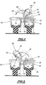
- the transfer and turning means 24 visible in the figures 2 and 3 comprise, in addition to the support levers 48 and 60 of the first and second conveyors, means for actuating the associated control arms 50 and 70.
- These actuation means are noted respectively 76 and 78. They are each formed by a fixed ramp forming a cam surface. These ramps are arranged laterally between the two conveyors on the length of the transfer section 25. They are adapted respectively for lifting the control arms 50, 70 from the ejection levers when their passage through the transfer section 25.
- the ramps have a profile such that, when they move over the transfer section 25, the two facing levers tilt in the same way next.
- the lever 48 is held in its transport position.
- the lever 60 is tilted until the arm of support 68 either in the immediate vicinity of the upper surface of the article resting on the support arm 46.
- the support arm 46 is gradually raised, while the support arm 68 is brought back simultaneously towards the loop 62.
- the support arms of the two adjacent levers define a space 80 of retention of an article during its transfer from the first to the second conveyor.
- the article In space 80, the article is confined and is notably substantially fully immobilized in rotation relative to the support arms 46 and 68.
- lever 48 is returned to the transport position on the drive loop 32.
- the face upper of the article resting on the lever 60 is then the face on which the article rested on lever 48.
- a first vision station 90 and a second station of vision 92 are arranged respectively on the first conveyor 20 and the second conveyor 22 . These are adapted respectively to capture at least a digital image of the exposed region of the article circulating on the first and second conveyors.
- Each vision station 90, 92 comprises for example two cameras noted 90A, 90B and 92A, 92B, respectively. These are arranged in the upper part of the associated conveyor 20, 22, on either side thereof. They are angularly offset from the vertical and their field of vision is oriented downwards towards the conveyor.
- the cameras are linked to the central information processing unit 30.
- the fruits are introduced in bulk into the loading station 10. These are thus poured onto the distribution section of the first conveyor.
- the fruits coming into contact with the rollers 40 are distributed under the action of their own weight in the cells 42 delimited between the rollers, so that each cell is occupied only by one fruit.
- the fruits are then successively weighed in the weighing station 12 and the weight of each fruit is sent to the central processing unit information 30.
- the fruit After weighing, the fruit enters the visual examination station 14. When they pass vertically from the vision station 90, two images of the exposed surface of each fruit are digitized and transmitted to the unit information processing center 30.
- the fruits, taken from the first conveyor 20, are successively transferred on the second conveyor 22 while being turned over.
- the central information processing unit 30 has then four images of the fruit taken from different angles. Of turns the fruit between the first and second conveyors, the memorized images cover most of the surface of the fruit, allowing a precise determination of its external appearance.
- Information received by the central information processing unit 30 and relating to the weight of each fruit, its external appearance and its nature allow to determine the channel 26 in which each fruit must be ejected.
- the central processing unit information processing 30 controls the tilting of the levers 60 when these pass over the selected channel.
- the trigger element 28A associated with the selected channel is activated during the passage of the lever to push the control arm 70 and thus cause the tilting fruit falling under its own weight into the filled canal corresponding water.
- the images of each item are all taken from the top of the item based on a conveyor, which avoids having to provide perforated conveyors.
- the weighing station 12 is arranged not on the first conveyor 20 but on the second conveyor 22 downstream of the station visual examination 14.
- the article sorting installation shown in FIG. 4 comprises also a loading station 110, a weighing station 112, a visual examination station 114 and an ejection zone or station 116.
- This station includes transfer means 118 of different structure of those used in the embodiment of FIG. 1.
- these transfer means comprise a single conveyor 119 extending from the loading station to the ejection station 116.
- This single conveyor has first and second rows of lateral transport 120, 122 extending parallel to each other and advancing simultaneously by being integral with the same drive chain. Between these two transport queues 120, 122, the conveyor 119 comprises a central file 124 moving at the same speed as the lateral files 120 and 122.
- the lateral lines 120, 122 and central 124 both extend over the entire length of the installation.
- the first line 120 crosses the loading station 110 and the weighing station 112.
- the visual examination station 114 extends over contiguous sections of the first and second lines 120, 122.
- First and second viewing stations 126, 128 are provided successively on the route of the means of transport 118. These vision stations are installed respectively on the first line 120 and in the second row 122. They are similar in nature to those noted 90, 92 in the embodiment of FIG. 1.
- the second line 122 extends after the second viewing station 128 in the ejection station 116.
- the lateral file 120 consists of a succession of elements 140 articulated to each other other.
- the lateral file 122 is also formed of a succession of elements 142 articulated to each other.
- the adjacent elements of two lines are interconnected transversely to the drive chain municipality closed in a loop, itself driven by a geared motor group not shown.
- the central file 124 comprises a succession of articulated elements 144 to each other to form a loop, this loop being integral corresponding elements 140 and 142 of the lateral rows.
- rollers 150 are rotary mounted. These rollers are similar to the rollers 40 of the first embodiment and ensure a distribution of the articles according to the length of the queue 120, when loaded in the loading station 110.
- First support levers 154 are articulated at one of their ends on the elements 144. These levers are adapted to be inserted between two successive rollers 150 of the first row and thus support a article.
- second levers 156 are also articulated on the elements 144 of the central file along the same axis as the first levers 154. These second levers 156 are adapted to bear on the elements 142 of the second file.
- Each of the levers 154 and 156 is articulated between its rest position resting on the mobile elements of the queue 120 or 122 and a position almost turned over on the other line, as illustrated on figure 5 in mixed line.
Landscapes
- Engineering & Computer Science (AREA)
- Mechanical Engineering (AREA)
- Multimedia (AREA)
- Sorting Of Articles (AREA)
- Investigating Materials By The Use Of Optical Means Adapted For Particular Applications (AREA)
- Eye Examination Apparatus (AREA)
- Branching, Merging, And Special Transfer Between Conveyors (AREA)
- Management, Administration, Business Operations System, And Electronic Commerce (AREA)
- Harvesting Machines For Specific Crops (AREA)
- Medicines Containing Plant Substances (AREA)
- Packaging Of Special Articles (AREA)
- Polysaccharides And Polysaccharide Derivatives (AREA)
- Supplying Of Containers To The Packaging Station (AREA)
- Discharge Of Articles From Conveyors (AREA)
Applications Claiming Priority (2)
| Application Number | Priority Date | Filing Date | Title |
|---|---|---|---|
| FR9812883A FR2784665B1 (fr) | 1998-10-14 | 1998-10-14 | Station d'examen visuel de fruits |
| FR9812883 | 1998-10-14 |
Publications (2)
| Publication Number | Publication Date |
|---|---|
| EP0993877A1 true EP0993877A1 (de) | 2000-04-19 |
| EP0993877B1 EP0993877B1 (de) | 2004-03-17 |
Family
ID=9531558
Family Applications (1)
| Application Number | Title | Priority Date | Filing Date |
|---|---|---|---|
| EP99402521A Expired - Lifetime EP0993877B1 (de) | 1998-10-14 | 1999-10-13 | Station zur visuellen Untersuchung von Früchten |
Country Status (8)
| Country | Link |
|---|---|
| US (1) | US6267222B1 (de) |
| EP (1) | EP0993877B1 (de) |
| AT (1) | ATE261785T1 (de) |
| DE (1) | DE69915558T2 (de) |
| DK (1) | DK0993877T3 (de) |
| ES (1) | ES2218966T3 (de) |
| FR (1) | FR2784665B1 (de) |
| PT (1) | PT993877E (de) |
Cited By (3)
| Publication number | Priority date | Publication date | Assignee | Title |
|---|---|---|---|---|
| NL1025702C2 (nl) * | 2004-03-12 | 2005-09-13 | Hortagro Internat B V | Sorteermachine. |
| WO2015165905A1 (fr) * | 2014-04-30 | 2015-11-05 | Maf Agrobotic | Dispositif d'analyse unilatérale de produits par retournement et dispositif de convoyage et de tri automatique l'incorporant |
| IT201700064382A1 (it) * | 2017-06-12 | 2018-12-12 | Linox Nastri Trasportatori S R L Abbreviabile In Linox S R L | Impianto per la selezione di prodotti ortofrutticoli. |
Families Citing this family (10)
| Publication number | Priority date | Publication date | Assignee | Title |
|---|---|---|---|---|
| US7025192B2 (en) * | 2001-08-17 | 2006-04-11 | Tetra Laval Holding & Finance S.A. | Device for turning objects |
| ATE327503T1 (de) * | 2003-04-18 | 2006-06-15 | M M O S P A Sa | Gerät zur optischen überprüfung der qualität der aussenoberfläche von gewölbt geformtem obst und gemüse verschiedenster form und grösse |
| CN100429502C (zh) * | 2004-12-14 | 2008-10-29 | 中国农业大学 | 一种快速无损检测苹果内部质量的方法 |
| CN100429501C (zh) * | 2004-12-14 | 2008-10-29 | 中国农业大学 | 一种快速无损检测鸭梨黑心病的方法 |
| ITBO20050426A1 (it) * | 2005-06-28 | 2006-12-29 | Unitec Srl | Metodo ed impianto per il trasporto e la selezione di prodotti ortofrutticoli |
| CN102218406B (zh) * | 2011-01-04 | 2013-06-12 | 华南理工大学 | 一种基于机器视觉的手机外壳缺陷智能检测装置 |
| EP3274281B1 (de) * | 2015-03-27 | 2023-08-30 | Unitec S.p.A. | Anordnung zur handhabung von obst- und gemüseprodukten |
| CN105293023B (zh) * | 2015-10-26 | 2018-01-09 | 无锡耐博机器人科技有限公司 | 一种自动化海绵理料机 |
| CN106027730A (zh) * | 2016-07-18 | 2016-10-12 | 苏州派斯威尔自动化科技有限公司 | 一种手机壳自动化智能检测系统 |
| IT202100018389A1 (it) * | 2021-07-13 | 2023-01-13 | Unitec Spa | Apparato di trasporto di prodotti ortofrutticoli |
Citations (5)
| Publication number | Priority date | Publication date | Assignee | Title |
|---|---|---|---|---|
| US4742921A (en) * | 1987-02-17 | 1988-05-10 | Staley 3Rd Wilford | Conveyor system |
| EP0415154A1 (de) * | 1989-08-10 | 1991-03-06 | Heuft Systemtechnik Gmbh | Verfahren zum Inspizieren von Gegenständen aus unterschiedlichen Blickwinkeln |
| JPH08175647A (ja) * | 1994-12-21 | 1996-07-09 | Ishii Ind Co Ltd | 搬送物選別装置 |
| JPH08225144A (ja) * | 1995-12-21 | 1996-09-03 | Ishii Ind Co Ltd | 鍵盤型搬送装置 |
| JPH09215963A (ja) * | 1996-02-09 | 1997-08-19 | Ishii Ind Co Ltd | 揺動式搬送装置 |
Family Cites Families (1)
| Publication number | Priority date | Publication date | Assignee | Title |
|---|---|---|---|---|
| DE19532943A1 (de) * | 1995-09-07 | 1997-03-13 | Hauni Maschinenbau Ag | Vorrichtung zum queraxialen Fördern und Drehen von stabförmigen Artikeln der tabakverarbeitenden Industrie |
-
1998
- 1998-10-14 FR FR9812883A patent/FR2784665B1/fr not_active Expired - Fee Related
-
1999
- 1999-10-13 ES ES99402521T patent/ES2218966T3/es not_active Expired - Lifetime
- 1999-10-13 AT AT99402521T patent/ATE261785T1/de not_active IP Right Cessation
- 1999-10-13 EP EP99402521A patent/EP0993877B1/de not_active Expired - Lifetime
- 1999-10-13 US US09/417,306 patent/US6267222B1/en not_active Expired - Fee Related
- 1999-10-13 DE DE69915558T patent/DE69915558T2/de not_active Expired - Fee Related
- 1999-10-13 DK DK99402521T patent/DK0993877T3/da active
- 1999-10-13 PT PT99402521T patent/PT993877E/pt unknown
Patent Citations (5)
| Publication number | Priority date | Publication date | Assignee | Title |
|---|---|---|---|---|
| US4742921A (en) * | 1987-02-17 | 1988-05-10 | Staley 3Rd Wilford | Conveyor system |
| EP0415154A1 (de) * | 1989-08-10 | 1991-03-06 | Heuft Systemtechnik Gmbh | Verfahren zum Inspizieren von Gegenständen aus unterschiedlichen Blickwinkeln |
| JPH08175647A (ja) * | 1994-12-21 | 1996-07-09 | Ishii Ind Co Ltd | 搬送物選別装置 |
| JPH08225144A (ja) * | 1995-12-21 | 1996-09-03 | Ishii Ind Co Ltd | 鍵盤型搬送装置 |
| JPH09215963A (ja) * | 1996-02-09 | 1997-08-19 | Ishii Ind Co Ltd | 揺動式搬送装置 |
Non-Patent Citations (3)
| Title |
|---|
| PATENT ABSTRACTS OF JAPAN vol. 096, no. 011 29 November 1996 (1996-11-29) * |
| PATENT ABSTRACTS OF JAPAN vol. 097, no. 001 31 January 1997 (1997-01-31) * |
| PATENT ABSTRACTS OF JAPAN vol. 097, no. 012 25 December 1997 (1997-12-25) * |
Cited By (5)
| Publication number | Priority date | Publication date | Assignee | Title |
|---|---|---|---|---|
| NL1025702C2 (nl) * | 2004-03-12 | 2005-09-13 | Hortagro Internat B V | Sorteermachine. |
| WO2005087394A1 (en) * | 2004-03-12 | 2005-09-22 | Hortagro International B.V. | Sorting machine with two cameras |
| WO2015165905A1 (fr) * | 2014-04-30 | 2015-11-05 | Maf Agrobotic | Dispositif d'analyse unilatérale de produits par retournement et dispositif de convoyage et de tri automatique l'incorporant |
| FR3020627A1 (fr) * | 2014-04-30 | 2015-11-06 | Maf Agrobotic | Dispositif d'analyse unilaterale de produits par retournement et dispositif de convoyage et de tri automatique l'incorporant |
| IT201700064382A1 (it) * | 2017-06-12 | 2018-12-12 | Linox Nastri Trasportatori S R L Abbreviabile In Linox S R L | Impianto per la selezione di prodotti ortofrutticoli. |
Also Published As
| Publication number | Publication date |
|---|---|
| ES2218966T3 (es) | 2004-11-16 |
| FR2784665A1 (fr) | 2000-04-21 |
| ATE261785T1 (de) | 2004-04-15 |
| PT993877E (pt) | 2004-08-31 |
| DK0993877T3 (da) | 2004-07-26 |
| EP0993877B1 (de) | 2004-03-17 |
| FR2784665B1 (fr) | 2001-01-26 |
| US6267222B1 (en) | 2001-07-31 |
| DE69915558D1 (de) | 2004-04-22 |
| DE69915558T2 (de) | 2004-08-05 |
Similar Documents
| Publication | Publication Date | Title |
|---|---|---|
| EP0993877B1 (de) | Station zur visuellen Untersuchung von Früchten | |
| EP3283857B1 (de) | Vorrichtung zum transport von objekten und mit solchen transportvorrichtungen ausgestattete förderungs- und wiegevorrichtung | |
| FR2519887A1 (fr) | Dispositif de tri sur un convoyeur horizontal | |
| FR3082511A1 (fr) | Dispositif de transport de type noria de plaques supports de produits de boulangerie ou similaires | |
| CA2943453A1 (fr) | Dispositif d'analyse unilaterale de produits par retournement et dispositif de convoyage et de tri automatique l'incorporant | |
| EP0283388B1 (de) | Kalibrierungssystem für Produkte, wie etwa Obst | |
| EP0299016B1 (de) | Verfahren und vorrichtung zum transport von stückgut auf einer förderbahn | |
| FR3092016A1 (fr) | Systeme de tri colis a debit eleve | |
| EP0810963B1 (de) | Zuführvorrichtung für eine sortiervorrichtung, sortiervorrichtung mit diese zuführvorrichtung, kalibrierung und verteilvorrichtung | |
| FR2976196A1 (fr) | Dispositif de convoyage d'objets tels que des fruits ou legumes a zones amont d'individualisation bilaterale | |
| FR2788043A1 (fr) | Convoyeur a chaine, tel que carrousel pour machine d'installation logistique, et machine telle que pour le tri d'objets plats | |
| FR2607121A1 (fr) | Convoyeur a accumulation | |
| FR2750682A1 (fr) | Dispositif destine a modifier l'orientation d'articles transportes, par exemple pour des installations de conditionnement automatiques | |
| FR2655630A1 (fr) | Machine pour distribuer individuellement et successivement, a une cadence determine, des articles initialement en vrac. | |
| FR2753683A1 (fr) | Dispositif de chargement d'articles a tete de distribution et d'accumulation | |
| EP0229805B1 (de) | Maschine zum automatischen einlegen von erzeugnissen in empfangszellen | |
| EP0027394A1 (de) | Verfahren und Vorrichtung zum Regeln der Transportgeschwindigkeit, insbesondere für den Zubringerförderer einer automatischen Sortieranlage | |
| FR2516486A1 (fr) | Convoyeur a compartiment permettant de transporter des objets sur un poste de pesee, destine en particulier a classer des fruits | |
| EP0478467A1 (de) | Einrichtung für Handhabung und Kalibrierung von Artikeln, namentlich Schalentiere und insbesondere Austern | |
| FR2728880A1 (fr) | Dispositif regulateur d'energie cinetique | |
| FR2662998A1 (fr) | Dispositif de conditionnement en continu de barquettes. | |
| CH383879A (fr) | Appareil de manutention de bouteilles | |
| FR2496597A1 (fr) | Dispositif de repartition d'objets en continu | |
| LU82594A1 (fr) | Systeme de distribution et de transfert de charges entre plusieurs convoyeurs dans une installation de manutention | |
| FR2602742A1 (fr) | Installation de distribution automatique de colis |
Legal Events
| Date | Code | Title | Description |
|---|---|---|---|
| PUAI | Public reference made under article 153(3) epc to a published international application that has entered the european phase |
Free format text: ORIGINAL CODE: 0009012 |
|
| AK | Designated contracting states |
Kind code of ref document: A1 Designated state(s): AT BE CH CY DE DK ES FI FR GB GR IE IT LI LU MC NL PT SE |
|
| AX | Request for extension of the european patent |
Free format text: AL;LT;LV;MK;RO;SI |
|
| 17P | Request for examination filed |
Effective date: 20000928 |
|
| AKX | Designation fees paid |
Free format text: AT BE CH CY DE DK ES FI FR GB GR IE IT LI LU MC NL PT SE |
|
| 17Q | First examination report despatched |
Effective date: 20021029 |
|
| GRAP | Despatch of communication of intention to grant a patent |
Free format text: ORIGINAL CODE: EPIDOSNIGR1 |
|
| GRAS | Grant fee paid |
Free format text: ORIGINAL CODE: EPIDOSNIGR3 |
|
| GRAA | (expected) grant |
Free format text: ORIGINAL CODE: 0009210 |
|
| AK | Designated contracting states |
Kind code of ref document: B1 Designated state(s): AT BE CH CY DE DK ES FI FR GB GR IE IT LI LU MC NL PT SE |
|
| REG | Reference to a national code |
Ref country code: GB Ref legal event code: FG4D Free format text: NOT ENGLISH |
|
| REG | Reference to a national code |
Ref country code: CH Ref legal event code: EP |
|
| GBT | Gb: translation of ep patent filed (gb section 77(6)(a)/1977) |
Effective date: 20040317 |
|
| REG | Reference to a national code |
Ref country code: IE Ref legal event code: FG4D Free format text: FRENCH |
|
| REF | Corresponds to: |
Ref document number: 69915558 Country of ref document: DE Date of ref document: 20040422 Kind code of ref document: P |
|
| REG | Reference to a national code |
Ref country code: GR Ref legal event code: EP Ref document number: 20040401148 Country of ref document: GR |
|
| REG | Reference to a national code |
Ref country code: SE Ref legal event code: TRGR |
|
| REG | Reference to a national code |
Ref country code: DK Ref legal event code: T3 |
|
| REG | Reference to a national code |
Ref country code: PT Ref legal event code: SC4A Free format text: AVAILABILITY OF NATIONAL TRANSLATION Effective date: 20040609 |
|
| PG25 | Lapsed in a contracting state [announced via postgrant information from national office to epo] |
Ref country code: LU Free format text: LAPSE BECAUSE OF NON-PAYMENT OF DUE FEES Effective date: 20041013 Ref country code: IE Free format text: LAPSE BECAUSE OF NON-PAYMENT OF DUE FEES Effective date: 20041013 Ref country code: GB Free format text: LAPSE BECAUSE OF NON-PAYMENT OF DUE FEES Effective date: 20041013 Ref country code: FI Free format text: LAPSE BECAUSE OF NON-PAYMENT OF DUE FEES Effective date: 20041013 Ref country code: CY Free format text: LAPSE BECAUSE OF NON-PAYMENT OF DUE FEES Effective date: 20041013 Ref country code: AT Free format text: LAPSE BECAUSE OF NON-PAYMENT OF DUE FEES Effective date: 20041013 |
|
| PG25 | Lapsed in a contracting state [announced via postgrant information from national office to epo] |
Ref country code: SE Free format text: LAPSE BECAUSE OF NON-PAYMENT OF DUE FEES Effective date: 20041014 Ref country code: ES Free format text: LAPSE BECAUSE OF NON-PAYMENT OF DUE FEES Effective date: 20041014 |
|
| PG25 | Lapsed in a contracting state [announced via postgrant information from national office to epo] |
Ref country code: MC Free format text: LAPSE BECAUSE OF NON-PAYMENT OF DUE FEES Effective date: 20041031 Ref country code: LI Free format text: LAPSE BECAUSE OF NON-PAYMENT OF DUE FEES Effective date: 20041031 Ref country code: CH Free format text: LAPSE BECAUSE OF NON-PAYMENT OF DUE FEES Effective date: 20041031 Ref country code: BE Free format text: LAPSE BECAUSE OF NON-PAYMENT OF DUE FEES Effective date: 20041031 |
|
| PG25 | Lapsed in a contracting state [announced via postgrant information from national office to epo] |
Ref country code: DK Free format text: LAPSE BECAUSE OF NON-PAYMENT OF DUE FEES Effective date: 20041101 |
|
| REG | Reference to a national code |
Ref country code: ES Ref legal event code: FG2A Ref document number: 2218966 Country of ref document: ES Kind code of ref document: T3 |
|
| PLBE | No opposition filed within time limit |
Free format text: ORIGINAL CODE: 0009261 |
|
| STAA | Information on the status of an ep patent application or granted ep patent |
Free format text: STATUS: NO OPPOSITION FILED WITHIN TIME LIMIT |
|
| 26N | No opposition filed |
Effective date: 20041220 |
|
| BERE | Be: lapsed |
Owner name: *XEDA INTERNATIONAL Effective date: 20041031 |
|
| PG25 | Lapsed in a contracting state [announced via postgrant information from national office to epo] |
Ref country code: NL Free format text: LAPSE BECAUSE OF NON-PAYMENT OF DUE FEES Effective date: 20050501 |
|
| PG25 | Lapsed in a contracting state [announced via postgrant information from national office to epo] |
Ref country code: DE Free format text: LAPSE BECAUSE OF NON-PAYMENT OF DUE FEES Effective date: 20050503 |
|
| PG25 | Lapsed in a contracting state [announced via postgrant information from national office to epo] |
Ref country code: GR Free format text: LAPSE BECAUSE OF NON-PAYMENT OF DUE FEES Effective date: 20050504 |
|
| EUG | Se: european patent has lapsed | ||
| GBPC | Gb: european patent ceased through non-payment of renewal fee |
Effective date: 20041013 |
|
| REG | Reference to a national code |
Ref country code: DK Ref legal event code: EBP |
|
| REG | Reference to a national code |
Ref country code: CH Ref legal event code: PL |
|
| PG25 | Lapsed in a contracting state [announced via postgrant information from national office to epo] |
Ref country code: FR Free format text: LAPSE BECAUSE OF NON-PAYMENT OF DUE FEES Effective date: 20050630 |
|
| NLV4 | Nl: lapsed or anulled due to non-payment of the annual fee |
Effective date: 20050501 |
|
| PG25 | Lapsed in a contracting state [announced via postgrant information from national office to epo] |
Ref country code: PT Free format text: LAPSE BECAUSE OF NON-PAYMENT OF DUE FEES Effective date: 20050713 |
|
| REG | Reference to a national code |
Ref country code: FR Ref legal event code: ST |
|
| PG25 | Lapsed in a contracting state [announced via postgrant information from national office to epo] |
Ref country code: IT Free format text: LAPSE BECAUSE OF NON-PAYMENT OF DUE FEES;WARNING: LAPSES OF ITALIAN PATENTS WITH EFFECTIVE DATE BEFORE 2007 MAY HAVE OCCURRED AT ANY TIME BEFORE 2007. THE CORRECT EFFECTIVE DATE MAY BE DIFFERENT FROM THE ONE RECORDED. Effective date: 20051013 |
|
| REG | Reference to a national code |
Ref country code: PT Ref legal event code: MM4A Effective date: 20050713 |
|
| REG | Reference to a national code |
Ref country code: ES Ref legal event code: FD2A Effective date: 20041014 |
|
| REG | Reference to a national code |
Ref country code: IE Ref legal event code: MM4A |
|
| BERE | Be: lapsed |
Owner name: *XEDA INTERNATIONAL Effective date: 20041031 |
|
| PG25 | Lapsed in a contracting state [announced via postgrant information from national office to epo] |
Ref country code: PT Free format text: LAPSE BECAUSE OF NON-PAYMENT OF DUE FEES Effective date: 20041013 |