EP0993904A2 - Entraínement linéaire - Google Patents
Entraínement linéaire Download PDFInfo
- Publication number
- EP0993904A2 EP0993904A2 EP99120109A EP99120109A EP0993904A2 EP 0993904 A2 EP0993904 A2 EP 0993904A2 EP 99120109 A EP99120109 A EP 99120109A EP 99120109 A EP99120109 A EP 99120109A EP 0993904 A2 EP0993904 A2 EP 0993904A2
- Authority
- EP
- European Patent Office
- Prior art keywords
- profile
- stop
- linear drive
- runner
- bumper
- Prior art date
- Legal status (The legal status is an assumption and is not a legal conclusion. Google has not performed a legal analysis and makes no representation as to the accuracy of the status listed.)
- Withdrawn
Links
Images

Classifications
-
- F—MECHANICAL ENGINEERING; LIGHTING; HEATING; WEAPONS; BLASTING
- F16—ENGINEERING ELEMENTS AND UNITS; GENERAL MEASURES FOR PRODUCING AND MAINTAINING EFFECTIVE FUNCTIONING OF MACHINES OR INSTALLATIONS; THERMAL INSULATION IN GENERAL
- F16C—SHAFTS; FLEXIBLE SHAFTS; ELEMENTS OR CRANKSHAFT MECHANISMS; ROTARY BODIES OTHER THAN GEARING ELEMENTS; BEARINGS
- F16C29/00—Bearings for parts moving only linearly
- F16C29/02—Sliding-contact bearings
-
- B—PERFORMING OPERATIONS; TRANSPORTING
- B23—MACHINE TOOLS; METAL-WORKING NOT OTHERWISE PROVIDED FOR
- B23Q—DETAILS, COMPONENTS, OR ACCESSORIES FOR MACHINE TOOLS, e.g. ARRANGEMENTS FOR COPYING OR CONTROLLING; MACHINE TOOLS IN GENERAL CHARACTERISED BY THE CONSTRUCTION OF PARTICULAR DETAILS OR COMPONENTS; COMBINATIONS OR ASSOCIATIONS OF METAL-WORKING MACHINES, NOT DIRECTED TO A PARTICULAR RESULT
- B23Q1/00—Members which are comprised in the general build-up of a form of machine, particularly relatively large fixed members
- B23Q1/25—Movable or adjustable work or tool supports
- B23Q1/26—Movable or adjustable work or tool supports characterised by constructional features relating to the co-operation of relatively movable members; Means for preventing relative movement of such members
-
- B—PERFORMING OPERATIONS; TRANSPORTING
- B23—MACHINE TOOLS; METAL-WORKING NOT OTHERWISE PROVIDED FOR
- B23Q—DETAILS, COMPONENTS, OR ACCESSORIES FOR MACHINE TOOLS, e.g. ARRANGEMENTS FOR COPYING OR CONTROLLING; MACHINE TOOLS IN GENERAL CHARACTERISED BY THE CONSTRUCTION OF PARTICULAR DETAILS OR COMPONENTS; COMBINATIONS OR ASSOCIATIONS OF METAL-WORKING MACHINES, NOT DIRECTED TO A PARTICULAR RESULT
- B23Q16/00—Equipment for precise positioning of tool or work into particular locations not otherwise provided for
- B23Q16/001—Stops, cams, or holders therefor
-
- B—PERFORMING OPERATIONS; TRANSPORTING
- B23—MACHINE TOOLS; METAL-WORKING NOT OTHERWISE PROVIDED FOR
- B23Q—DETAILS, COMPONENTS, OR ACCESSORIES FOR MACHINE TOOLS, e.g. ARRANGEMENTS FOR COPYING OR CONTROLLING; MACHINE TOOLS IN GENERAL CHARACTERISED BY THE CONSTRUCTION OF PARTICULAR DETAILS OR COMPONENTS; COMBINATIONS OR ASSOCIATIONS OF METAL-WORKING MACHINES, NOT DIRECTED TO A PARTICULAR RESULT
- B23Q16/00—Equipment for precise positioning of tool or work into particular locations not otherwise provided for
- B23Q16/008—Cushioning the abutting movement
-
- B—PERFORMING OPERATIONS; TRANSPORTING
- B23—MACHINE TOOLS; METAL-WORKING NOT OTHERWISE PROVIDED FOR
- B23Q—DETAILS, COMPONENTS, OR ACCESSORIES FOR MACHINE TOOLS, e.g. ARRANGEMENTS FOR COPYING OR CONTROLLING; MACHINE TOOLS IN GENERAL CHARACTERISED BY THE CONSTRUCTION OF PARTICULAR DETAILS OR COMPONENTS; COMBINATIONS OR ASSOCIATIONS OF METAL-WORKING MACHINES, NOT DIRECTED TO A PARTICULAR RESULT
- B23Q5/00—Driving or feeding mechanisms; Control arrangements therefor
- B23Q5/54—Arrangements or details not restricted to group B23Q5/02 or group B23Q5/22 respectively, e.g. control handles
- B23Q5/58—Safety devices
-
- B—PERFORMING OPERATIONS; TRANSPORTING
- B29—WORKING OF PLASTICS; WORKING OF SUBSTANCES IN A PLASTIC STATE IN GENERAL
- B29C—SHAPING OR JOINING OF PLASTICS; SHAPING OF MATERIAL IN A PLASTIC STATE, NOT OTHERWISE PROVIDED FOR; AFTER-TREATMENT OF THE SHAPED PRODUCTS, e.g. REPAIRING
- B29C45/00—Injection moulding, i.e. forcing the required volume of moulding material through a nozzle into a closed mould; Apparatus therefor
- B29C45/14—Injection moulding, i.e. forcing the required volume of moulding material through a nozzle into a closed mould; Apparatus therefor incorporating preformed parts or layers, e.g. injection moulding around inserts or for coating articles
- B29C45/14008—Inserting articles into the mould
-
- B—PERFORMING OPERATIONS; TRANSPORTING
- B29—WORKING OF PLASTICS; WORKING OF SUBSTANCES IN A PLASTIC STATE IN GENERAL
- B29C—SHAPING OR JOINING OF PLASTICS; SHAPING OF MATERIAL IN A PLASTIC STATE, NOT OTHERWISE PROVIDED FOR; AFTER-TREATMENT OF THE SHAPED PRODUCTS, e.g. REPAIRING
- B29C45/00—Injection moulding, i.e. forcing the required volume of moulding material through a nozzle into a closed mould; Apparatus therefor
- B29C45/17—Component parts, details or accessories; Auxiliary operations
- B29C45/40—Removing or ejecting moulded articles
- B29C45/42—Removing or ejecting moulded articles using means movable from outside the mould between mould parts, e.g. robots
-
- F—MECHANICAL ENGINEERING; LIGHTING; HEATING; WEAPONS; BLASTING
- F16—ENGINEERING ELEMENTS AND UNITS; GENERAL MEASURES FOR PRODUCING AND MAINTAINING EFFECTIVE FUNCTIONING OF MACHINES OR INSTALLATIONS; THERMAL INSULATION IN GENERAL
- F16F—SPRINGS; SHOCK-ABSORBERS; MEANS FOR DAMPING VIBRATION
- F16F7/00—Vibration-dampers; Shock-absorbers
- F16F7/12—Vibration-dampers; Shock-absorbers using plastic deformation of members
-
- F—MECHANICAL ENGINEERING; LIGHTING; HEATING; WEAPONS; BLASTING
- F16—ENGINEERING ELEMENTS AND UNITS; GENERAL MEASURES FOR PRODUCING AND MAINTAINING EFFECTIVE FUNCTIONING OF MACHINES OR INSTALLATIONS; THERMAL INSULATION IN GENERAL
- F16C—SHAFTS; FLEXIBLE SHAFTS; ELEMENTS OR CRANKSHAFT MECHANISMS; ROTARY BODIES OTHER THAN GEARING ELEMENTS; BEARINGS
- F16C2322/00—Apparatus used in shaping articles
- F16C2322/39—General buildup of machine tools, e.g. spindles, slides, actuators
Definitions
- the invention relates to a linear drive with a profile, with a slider that can be moved on the profile, and with a stop for the runner at the end of the profile.
- Linear drives are used in handling technology to Handling elements, for example grippers and the like, along an axis to move from a first point to a second point.
- a typical example of such a handling technique is a handling system for a plastic injection molding machine.
- Such a handling system is provided for when opened Tool of the plastic injection molding machine between the mold halves retract and e.g. a molded plastic product from the tool.
- the handling system can also be used to perform additional operations execute, e.g. inserting parts into the tool, Remove plastic products from cones or threads or unscrew or the like
- the runner can be equipped with a gripper be equipped for further functions, e.g. with a cooling, a rotating device and the like.
- a gripper be equipped for further functions, e.g. with a cooling, a rotating device and the like.
- this Trap is the mass of the runner together with the connected Aggregates relatively high, so that at full speed moving runners have a relatively high kinetic energy represents. If such a runner at high speed collides with a conventional stop, it can consequently lead to undesirable consequences.
- the attack namely is elastic, it is at high speed and mass impacting runners from the elastic stop reflects and can damage other vehicles when reversing Cause components of the handling system.
- the stop on the other hand, if it is undersized, it will possibly from the bouncing runner due to the high Speed and high mass demolished, leaving the runner is released from the profile.
- the invention is based on the object, one Linear drive of the type mentioned, especially for the Application as a handling system in a plastic injection molding machine, in that the above mentioned disadvantages can be avoided.
- the object on which the invention is based is achieved in this way completely solved. If namely a defined plastically deformable Element is provided at the stop, the kinetic Energy of the runner traveling at high speed high mass in a simple way in deformation or thermal energy can be converted without other components of the linear drive or other surrounding components are damaged. With suitable dimensions, it is particularly prevented that the runner, when hitting the stop of this is reflected, which leads to further uncontrolled consequences can lead.
- the Stop a bumper at the end of the profile and in the path of movement of the runner is arranged, the bumper connected to the profile via the deformable element is.
- This measure has the advantage that the introduction of force into the plastically deformable element can be done directly because the impacting runner hits the bumper and the kinetic energy from the runner to the bumper without further Transfer intermediate stages directly to the deformable element becomes.
- the deformable element can be clamped between the bumper and the profile.
- This measure has the advantage that the deformation of the element immediately when the runner hits the stop can start.
- some deformable elements namely initially only one e.g. linear compression taking place during the actual deformation process in the form of a fold or a buckling of deformation elements only after exceeding a certain threshold. So if you provides for the deformable element to be preloaded this threshold is already overcome by pretensioning, so that when the runner hits the stop immediately the actual energy-converting deformation process begins.
- plastically deformable Element is a compression tube.
- Fig. 1 designates a total of a linear drive, which in essentially of a linear profile 12 and one on the Profile 12 movable runner 14 is made. If in the present Context of "linear drive” is mentioned, so it is in primarily a drive where a runner on a Profile is movable along a linear axis 15. It understands however, that the axis is also somewhat curved can run.
- a double arrow 16 indicates that the runner 14 is movable in both directions on the profile 12.
- the traversing means themselves and the associated control for the Runners 14 are not shown in FIG. 1 for clarity shown.
- the rotor 14 is usually on the profile 12 along the axis 15 proceed in such a way that it is always a certain distance from the End of the profile 12 complies. In the event that a malfunction occurs, however, is a stop 17 at the end of the profile 12 provided.
- the stop 17 is a mechanical stop.
- the stop 17 is intended to prevent the runner 14 jumps out of the profile 12 in an uncontrolled manner and thereby possibly causing damage.
- the stop 17 designed as a bumper 18, i.e. as a kind Bumper that at the end of the profile 12 in the trajectory of the Runner 14 is arranged.
- the bumper 18 has one End face 20 facing rotor 14, onto which rotor 14 collides with an end face 22 if the above Malfunction should occur.
- the bumper 18 connects to the profile 12, as explained in detail will be.
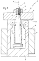
- FIG. 2 shows details of the in a cross-sectional representation Screw connection 24.
- a rod 30 running in the axis 15 provided that extends through a bore 31 in the bumper 18.
- the rod 30 is at its upper end in FIG provided with a thread 32 onto which a nut 34 is screwed is.
- the nut 34 is up to a surface 36 of the bumper 18th screwed on.
- the rod 30 is with a head 38 enlarged in cross section.
- the rod 30 dips with its head 38 into one along the axis 15 running bore 40 in profile 12.
- the bore 40 is enlarged itself inwards via a transition 42 into a room 44, the lower end of the rod 30 in FIG. 2 and the head 38 records.
- a stop disk 46 is in the Profile 12 attached. Between the stop plate 46 and the Head 38, a compression tube 48 is arranged.
- the upsetting pipe 48 is made preferably made of aluminum or another suitable Material with high deformation energy.
- the runner 14 will move on the profile 12, without the end face 22 of the rotor 14 on the end face 20th of the bumper 18 crashes.
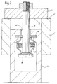
- Fig. 3 a situation is now shown in which the runner 14 at high speed and therefore with high kinetic Energy has accumulated on the bumper 18. So far in Fig. 3 Elements are shown that are different from the representation in Fig. 2 have performed a movement, these are elements provided with an apostrophe at their reference numbers.
Landscapes
- Engineering & Computer Science (AREA)
- Mechanical Engineering (AREA)
- General Engineering & Computer Science (AREA)
- Manufacturing & Machinery (AREA)
- Robotics (AREA)
- Transmission Devices (AREA)
- Bearings For Parts Moving Linearly (AREA)
- Moulds For Moulding Plastics Or The Like (AREA)
- Vibration Dampers (AREA)
Applications Claiming Priority (6)
| Application Number | Priority Date | Filing Date | Title |
|---|---|---|---|
| DE19847740A DE19847740C1 (de) | 1998-10-16 | 1998-10-16 | Verfahren zum Steuern eines Bewegungsablaufs eines bewegbaren Bauteils einer Kunststoff-Spritzgießmaschine |
| DE19847740 | 1998-10-16 | ||
| DE19848420 | 1998-10-21 | ||
| DE19848420A DE19848420C1 (de) | 1998-10-21 | 1998-10-21 | Kunststoff-Spritzgießanlage mit Handlinggerät |
| DE19905560 | 1999-02-11 | ||
| DE19905560 | 1999-02-11 |
Publications (2)
| Publication Number | Publication Date |
|---|---|
| EP0993904A2 true EP0993904A2 (fr) | 2000-04-19 |
| EP0993904A3 EP0993904A3 (fr) | 2001-05-09 |
Family
ID=27218738
Family Applications (1)
| Application Number | Title | Priority Date | Filing Date |
|---|---|---|---|
| EP99120109A Withdrawn EP0993904A3 (fr) | 1998-10-16 | 1999-10-08 | Entraínement linéaire |
Country Status (3)
| Country | Link |
|---|---|
| EP (1) | EP0993904A3 (fr) |
| JP (1) | JP2000304041A (fr) |
| DE (1) | DE19949529A1 (fr) |
Cited By (4)
| Publication number | Priority date | Publication date | Assignee | Title |
|---|---|---|---|---|
| CN103470592A (zh) * | 2013-09-18 | 2013-12-25 | 贵州航天精工制造有限公司 | 一种用镶嵌件在软基材料上的连接固定方法 |
| CN106594162A (zh) * | 2016-12-07 | 2017-04-26 | 上海交通大学 | 一种液压式动力反共振隔振装置 |
| US10837530B2 (en) | 2015-12-04 | 2020-11-17 | Ratier Figeac | Actuator of an aircraft with an energy-absorbing limit stop with a destructible and detachable bearing surface |
| WO2024056295A1 (fr) * | 2022-09-13 | 2024-03-21 | Schunk Electronic Solutions Gmbh | Unité linéaire possédant un amortisseur de collision intégré |
Families Citing this family (1)
| Publication number | Priority date | Publication date | Assignee | Title |
|---|---|---|---|---|
| US9016448B2 (en) * | 2012-11-27 | 2015-04-28 | The Boeing Company | Energy absorbing device |
Family Cites Families (1)
| Publication number | Priority date | Publication date | Assignee | Title |
|---|---|---|---|---|
| FR2465930A1 (fr) * | 1979-09-20 | 1981-03-27 | Tech Meca Indles | Dispositif de butee de fins de course d'un organe mobile |
-
1999
- 1999-10-08 EP EP99120109A patent/EP0993904A3/fr not_active Withdrawn
- 1999-10-14 DE DE19949529A patent/DE19949529A1/de not_active Ceased
- 1999-10-14 JP JP11292694A patent/JP2000304041A/ja active Pending
Cited By (5)
| Publication number | Priority date | Publication date | Assignee | Title |
|---|---|---|---|---|
| CN103470592A (zh) * | 2013-09-18 | 2013-12-25 | 贵州航天精工制造有限公司 | 一种用镶嵌件在软基材料上的连接固定方法 |
| CN103470592B (zh) * | 2013-09-18 | 2015-05-13 | 贵州航天精工制造有限公司 | 一种用镶嵌件在软基材料上的连接固定方法 |
| US10837530B2 (en) | 2015-12-04 | 2020-11-17 | Ratier Figeac | Actuator of an aircraft with an energy-absorbing limit stop with a destructible and detachable bearing surface |
| CN106594162A (zh) * | 2016-12-07 | 2017-04-26 | 上海交通大学 | 一种液压式动力反共振隔振装置 |
| WO2024056295A1 (fr) * | 2022-09-13 | 2024-03-21 | Schunk Electronic Solutions Gmbh | Unité linéaire possédant un amortisseur de collision intégré |
Also Published As
| Publication number | Publication date |
|---|---|
| EP0993904A3 (fr) | 2001-05-09 |
| JP2000304041A (ja) | 2000-10-31 |
| DE19949529A1 (de) | 2000-07-27 |
Similar Documents
| Publication | Publication Date | Title |
|---|---|---|
| DE19717473B4 (de) | Energieabsorberelement | |
| EP0943525B1 (fr) | Colonne de direction d'un véhicule automobile | |
| EP3261149A1 (fr) | Dispositif de fixation | |
| EP3908499B1 (fr) | Colonne de direction pour un véhicule automobile | |
| WO2017108021A1 (fr) | Dispositif de sécurité pour un véhicule à moteur comprenant un pêne pivotant et une position de préverrouillage et une position de verrouillage principal | |
| DE2148860A1 (de) | Reibungs-Zugkupplung,insbesondere fuer Eisenbahnwagen | |
| DE1947819C3 (de) | Vorrichtung zur Aufnahme übergroßer Stöße, die insbesondere einer Mittelpufferkupplung für Schienenfahrzeuge nachgeschaltet ist | |
| WO2007101565A1 (fr) | Arrangement de colonne de direction pour véhicules automobiles | |
| EP3459828A1 (fr) | Dispositif de transfert de forces lors de la collision d'un véhicule automobile | |
| DE102017104000A1 (de) | Heißkanalvorrichtung mit einer Überlastsicherungseinrichtung | |
| EP3530544A1 (fr) | Dispositif de déformation pourvu de protection anti-chevauchement pour véhicules ferroviaires | |
| EP0993904A2 (fr) | Entraínement linéaire | |
| WO2014180672A1 (fr) | Support de carrosserie pour véhicule automobile | |
| DE102008000936B4 (de) | Radaufhängung für ein Fahrzeug und Verbindungselement für eine solche Radaufhängung | |
| WO2017216348A1 (fr) | Colonne de direction pour véhicule à moteur | |
| DE102018220175A1 (de) | Lenksäule für ein Kraftfahrzeug | |
| EP1637426B1 (fr) | Tampon | |
| DE4441020C1 (de) | Stoßdämpfervorrichtung für Laufwagen insbesondere für Folienreckanlagen | |
| DE102017206277A1 (de) | Lenksäule mit Energieabsorptionsvorrichtung für ein Kraftfahrzeug | |
| DE69715683T2 (de) | Linearantriebsvorrichtung | |
| EP0807225B1 (fr) | Commande lineaire servant a changer la position d'un organe, en particulier un element d'aile d'avion | |
| EP3771609B1 (fr) | Tampon plongeur pourvu de poussoir enrobé par de section | |
| EP1193090B1 (fr) | Tampon de butée | |
| EP2882604B1 (fr) | Pédale de véhicule avec points de rupture en cas de choc | |
| EP2100780A1 (fr) | Système de protection contre les tonneaux avec un arceau extensible |
Legal Events
| Date | Code | Title | Description |
|---|---|---|---|
| PUAI | Public reference made under article 153(3) epc to a published international application that has entered the european phase |
Free format text: ORIGINAL CODE: 0009012 |
|
| AK | Designated contracting states |
Kind code of ref document: A2 Designated state(s): AT BE CH CY DE DK ES FI FR GB GR IE IT LI LU MC NL PT SE |
|
| AX | Request for extension of the european patent |
Free format text: AL;LT;LV;MK;RO;SI |
|
| PUAL | Search report despatched |
Free format text: ORIGINAL CODE: 0009013 |
|
| AK | Designated contracting states |
Kind code of ref document: A3 Designated state(s): AT BE CH CY DE DK ES FI FR GB GR IE IT LI LU MC NL PT SE |
|
| AX | Request for extension of the european patent |
Free format text: AL;LT;LV;MK;RO;SI |
|
| 17P | Request for examination filed |
Effective date: 20011009 |
|
| AKX | Designation fees paid |
Free format text: AT BE CH CY DE DK ES FI FR GB GR IE IT LI LU MC NL PT SE |
|
| 18D | Application deemed to be withdrawn |
Effective date: 20030501 |