EP0994055A2 - Vorrichtung zur Übertragung von doppelseitig haftendem Verbindungsmaterial - Google Patents
Vorrichtung zur Übertragung von doppelseitig haftendem Verbindungsmaterial Download PDFInfo
- Publication number
- EP0994055A2 EP0994055A2 EP99118834A EP99118834A EP0994055A2 EP 0994055 A2 EP0994055 A2 EP 0994055A2 EP 99118834 A EP99118834 A EP 99118834A EP 99118834 A EP99118834 A EP 99118834A EP 0994055 A2 EP0994055 A2 EP 0994055A2
- Authority
- EP
- European Patent Office
- Prior art keywords
- substrate
- carrier material
- pressure guide
- guide device
- rest position
- Prior art date
- Legal status (The legal status is an assumption and is not a legal conclusion. Google has not performed a legal analysis and makes no representation as to the accuracy of the status listed.)
- Withdrawn
Links
Images

Classifications
-
- B—PERFORMING OPERATIONS; TRANSPORTING
- B65—CONVEYING; PACKING; STORING; HANDLING THIN OR FILAMENTARY MATERIAL
- B65H—HANDLING THIN OR FILAMENTARY MATERIAL, e.g. SHEETS, WEBS, CABLES
- B65H19/00—Changing the web roll
- B65H19/10—Changing the web roll in unwinding mechanisms or in connection with unwinding operations
- B65H19/102—Preparing the leading end of the replacement web before splicing operation; Adhesive arrangements on leading end of replacement web; Tabs and adhesive tapes for splicing
-
- B—PERFORMING OPERATIONS; TRANSPORTING
- B65—CONVEYING; PACKING; STORING; HANDLING THIN OR FILAMENTARY MATERIAL
- B65H—HANDLING THIN OR FILAMENTARY MATERIAL, e.g. SHEETS, WEBS, CABLES
- B65H37/00—Article or web delivery apparatus incorporating devices for performing specified auxiliary operations
- B65H37/002—Web delivery apparatus, the web serving as support for articles, material or another web
-
- Y—GENERAL TAGGING OF NEW TECHNOLOGICAL DEVELOPMENTS; GENERAL TAGGING OF CROSS-SECTIONAL TECHNOLOGIES SPANNING OVER SEVERAL SECTIONS OF THE IPC; TECHNICAL SUBJECTS COVERED BY FORMER USPC CROSS-REFERENCE ART COLLECTIONS [XRACs] AND DIGESTS
- Y10—TECHNICAL SUBJECTS COVERED BY FORMER USPC
- Y10T—TECHNICAL SUBJECTS COVERED BY FORMER US CLASSIFICATION
- Y10T156/00—Adhesive bonding and miscellaneous chemical manufacture
- Y10T156/17—Surface bonding means and/or assemblymeans with work feeding or handling means
- Y10T156/1702—For plural parts or plural areas of single part
- Y10T156/1705—Lamina transferred to base from adhered flexible web or sheet type carrier
- Y10T156/1707—Discrete spaced laminae on adhered carrier
Definitions
- the invention relates to a device for transmitting a double-sided adhesive Connection material, in particular consisting of spaced apart Connecting sheets, from a receiving the connecting material, in particular strip-shaped, carrier material on a substrate, in particular on the beginning of one web of material to connect to the end of another Material web, with a pressure guide device for guiding the carrier material and pressing the carrier material onto the substrate.
- a double-sided adhesive Connection material in particular consisting of spaced apart Connecting sheets
- Such a device is usually installed in the splicing device Bobbin changer used in the ongoing supply of consumers, for example tobacco processing machines or packaging machines Paper and film webs changing from a reeling bobbin to a new one Bobine takes place, with the end of the material web of the running bobbin with Help of the double-sided adhesive connecting material with the beginning of the Material web of the new bobbin is connected.
- the pressure guide device to train as a transfer carriage, the linear and transverse to one as Substrate provided resting web of material is movable and a Carrier material between a supply roll and an empties roll leading and deflecting and contacting the material web during the carriage movement Has pinch roller.
- Strip-shaped carrier material used on one side as double-sided adhesive connecting material spaced connecting sheets are arranged.
- the invention proposes the pressure guide device to be modified so that it is between a rest position, in the the carrier material is at a distance from the substrate, and one Working position, in which the pressure control device with its carrier material the connecting material receiving front side in sections on brings the substrate, is movably mounted, and to provide an engagement element, that between a rest position in which it is disengaged from the substrate and an engagement position in which it is in engagement with the substrate is located, so that it can be moved from its engaged position into its Rest position can only be returned after the pressure control device Has left working position.
- the pressure guide device In the construction according to the invention needs to transfer the connecting material on the substrate, the pressure guide device only from their Rest position to be moved to their working position, in which the carrier material with its front side receiving the connecting material in contact with the Arrives substrate, so that the connecting material to lie on the substrate comes and adheres to it.
- Engagement element is brought from its rest position into its engagement position, in the it engages the substrate. Then the pressure control device moves back from its working position to its rest position the pressure guide device with the carrier material, whereby the double-sided adhesive connecting material detaches from the carrier material and on the substrate remains. While the pressure control device leaves its working position, the engaging element still remains in its engaging position, causing the substrate remains fixed in place.
- the invention offers a particularly simple, but reliable and effective construction for transferring a double-sided adhesive Connection material from the carrier material to a substrate.
- the engagement element is designed as a clamping element, which in its Engagement position under pressure on the substrate.
- a support element can be provided on which the substrate lies on.
- the engaging element should preferably be towards the substrate be spring biased.
- the engaging element In order to close the substrate through the engagement element as close as possible to that point, to which the double-sided adhesive connecting material is applied, and thus to fix effectively, the engaging element should expediently be adjacent be arranged to the pressure guide.
- the engagement element should be with the Pressure guide device can be coupled.
- the engaging element can preferably be movably mounted on the pressure guide device.
- Another currently particularly preferred embodiment is characterized by this from that the pressure control device between its rest position and its Working position is pivotally mounted.
- a transport device for the carrier material is usually provided, which has a supply roll and an empties roll.
- the pressure guide device should expediently be arranged on the transport device.
- a braking device should be provided, which on the Supply role works.
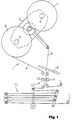
- a bobbin changer 1 is shown schematically in FIG a packaging machine or a tobacco processing machine becomes.
- the bobbin changer shown comprises one that can be pivoted through 180 ° Carrier 2 with two reel seats 3 and 4 for a straight old Bobine 6 and a new Bobine 7.
- the running material web 8 of the old Bobine 6 is via a known loop memory 11 to a not shown downstream machine led to further processing.
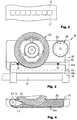
- This device 16 for transferring double-sided adhesive connecting sheets 17 is shown in more detail in FIGS. 3 to 6.
- the device 16 has a base plate 18 which extends over lateral arms 19 an axis 20 is pivotally mounted.
- the axis 20 forms a pivot axis which is parallel to Base plate 18, but laterally offset to this.
- a supply roll 22 and an empty goods roll 24 are rotatable on the base plate 18 stored.
- the empties roll 24 is arranged coaxially to the latter Knob 26 manually rotatable.
- On the supply roll 22 is a strip of carrier material 26 wound on the one behind the other in the longitudinal direction spaced apart, the double-sided adhesive connecting sheets 17 are arranged.
- the empties roll 24 serves to wind up the empty carrier material strip 26, after the connecting sheets 17 have been removed from this, what will be described in more detail below.
- the supply roll 22 and the Empties rolls 24 are detachably fastened on thorns, which are not specified.
- the Axis 20 adjacent lower portion of the base plate 18 laterally one Terminal block 28 arranged.
- the terminal block 28 extends in the longitudinal direction parallel to the axis 20 and has a flat at its lower free end Pressure surface 28a, which also runs parallel to the axis 20.
- the Clamping strip 28 transversely to its longitudinal extent and thus transversely to its pressing surface 28a movably mounted on the base plate 18 and is thereby by two Springs 30 biased in the direction away from the base plate 18.
- the Terminal block 28 mounted so that it between a first end position shown in FIG 5, in which it projects beyond the lower portion of the base plate 18, and one 6 in the second end position according to FIG essentially aligned with the underside of the base plate 18.
- the carrier material strip 26 with the connecting sheets 17 sitting thereon from the supply roll 22 with the aid of a Deflection roller 32 unwound.
- the axes of rotation of the supply roll 22, the empties roll 24 and the deflection roller 32 run parallel in the exemplary embodiment shown to each other.
- a pressure guide section 34 arranged on the Base plate 18 attached or connected in one piece with this.
- the pressure guide section 34 has on its underside adjacent to axis 20 a flat contact surface 34a on which the carrier material strip 26 with the double-sided adhesive connecting sheets 17 sitting thereon after deflection is guided along by the deflection roller 32.
- On - according to Figure 4 on the right - from the deflection roller 32 is the distal end of the contact surface 34a Carrier strip 26 deflected to the empties roll 24.
- the terminal block 28 is laterally on the lower portion of the base plate 18 arranged that it covers the pressure guide section 34 laterally.
- the deflection roller 32 and the pressing guide section 34 are shown in FIG 4 the terminal block 28 omitted.
- the contact surface 34a of the pressure guide section 34 extends parallel to the pressing surface 28a of the terminal block 28, wherein the spanned by the pressing surface 28a and the contact surface 34a Layers also run parallel to each other.
- the deflection roller 32 and the contact surface 34a of the pressure guide section 34 thus form a guide for the carrier material strip 26 between the Supply roll 22 and the empties roll 24.
- To generate a bias in Carrier material strip 26 is the supply roll 22 with one in the figures not closer adjustable friction brake shown.
- the direction of rotation of the empties roll 24 is by a freewheel, also not shown in the figures given.
- the running web of material 9 is new Bobine 7 led over a pad 36.
- the support 36 is provided with a suction device, of which in FIGS 6 only the connection 38 is shown schematically.
- the pressure guide section arrives 34 with its contact surface 34a in contact with the one lying on the support 36 Material web 9.
- the arrangement is such that the contact surface 34a of the pressure guide section 34 parallel to the material web 9 receiving and not shown in the figures bearing surface of the Recording 36 extends.
- the connection sheets 17 arrive on the guided along the contact surface 34a of the pressure guide section 34 Section of the carrier material strip 26 in contact with that on the support 36 lying material web 9. Since the connecting sheets 17 adhere on both sides, This creates an adhesive bond between the connection sheets 17 and the material web 9.
- the base plate 18 out of its working position according to Figure 6 again is pivoted back into its rest position according to FIG. 5, the carrier material strip 26 taken accordingly, whereby the double-sided adhesive Connection leaflets 17 from the along the contact surface 34a of the pressure guide section 34 loose section of the carrier material strip 26 and remain on the material web 9 in the arrangement shown in Figure 2.
- the double-sided adhesive connecting sheets 17 used adhesive materials and those for the carrier material strips 26 and the material web 9 used materials selected so that the connecting sheets 17 stronger on the material web 9 than on the carrier material strip 26 adhere so that the connecting sheets 17 when pivoting back Base plate 18 can more easily detach from the carrier material strip 26.
- the terminal block prevents such unintentional entrainment of the material web 9 28. This presses the base plate 18 when it swings back Material web 9 initially against the support 36 and thus prevents unintentional detachment of the material web 9 from the support 36.
- This is achieved Effect of the terminal block 28 by the previously described movable storage approximately vertical to the material web 9 and the action of the spring 30 which the terminal block 28 biased towards the material web 9 and thus the support 36, whereby the material web 9 between the pressing surface 28a of the clamping strip 28 and the pad 36 is clamped and thus remains on it.
- the movement stroke of the Terminal strip 28 thus corresponds to the length of the first part of the swivel path Base plate 18 from its working position according to Figure 6 in the direction of its rest position 5, during which the terminal block 28 in contact with the Material web 9 remains before it is lifted from it and into the Rest position of the base plate 18 is taken.
- the Empties roll 24 continues to be turned with the help of the rotary knob 26 until the new connecting sheets 17 bearing subsequent section of the substrate strip 26 completely along the contact surface 34a of the pressure guide section 34 extends.
- the device is now ready for transmission new connecting sheets 17 from the carrier material strip 26 onto the material web 9 in the manner previously described.
Landscapes
- Replacement Of Web Rolls (AREA)
Abstract
Description
- Figur 1
- eine Spleißvorrichtung innerhalb eines vereinfacht dargestellten Bobinenwechslers mit schematisch angedeuteter Vorrichtung zur Übertragung von Verbindungsblättchen;
- Figur 2
- eine Draufsicht auf eine mit Verbindungsblättchen versehene Materialbahn;
- Figur 3
- die Vorrichtung zur Übertragung der Verbindungsblättchen in einer Seitenansicht;
- Figur 4
- eine ausschnittsweise Darstellung eines Abschnittes der Vorrichtung gemäß Figur 3 bei weggelassener Klemmleiste;
- Figur 5
- eine um 90° gegenüber der Darstellung von Figur 3 gedrehte Stirnansicht der Vorrichtung zur Übertragung der Verbindungsblättchen in ihrer Ruhestellung; und
- Figur 6
- die gleiche Ansicht wie Figur 5, wobei sich die Vorrichtung jedoch in ihrer Arbeitsstellung befindet.
Claims (10)
- Vorrichtung (16) zur Übertragung eines doppelseitig haftenden Verbindungsmaterials (17), insbesondere bestehend aus voneinander beabstandeten Verbindungsblättchen (17), von einem das Verbindungsmaterial (17) aufnehmenden, insbesondere streifenförmigen, Trägermaterial (26) auf ein Substrat (9), insbesondere auf den Anfang einer Materialbahn (9) zum Verbinden mit dem Ende einer anderen Materialbahn (8), miteiner Andrückführungseinrichtung (18, 34) zum Führen des Trägermaterials (26) und Andrücken des Trägermaterials (26) auf das Substrat (9),
dadurch gekennzeichnet, daßdie Andrückführungseinrichtung (18, 34) zwischen einer Ruhestellung, in der sich das Trägermaterial (26) in einem Abstand vom Substrat (9) befindet, und einer Arbeitsstellung, in der die Andrückführungseinrichtung (18, 34) das Trägermaterial (26) mit seiner das Verbindungsmaterial (17) aufnehmenden Seite abschnittsweise in Anlage an das Substrat (9) bringt, bewegbar gelagert ist undein Eingriffselement (28) vorgesehen ist, das zwischen einer Ruhestellung, in der es sich außer Eingriff vom Substrat (9) befindet, und einer Eingriffsstellung, in der es sich in Eingriff mit dem Substrat (9) befindet, derart verbringbar ist, daß es von seiner Eingriffsstellung in seine Ruhestellung nur zurückführbar ist, nachdem die Andrückführungseinrichtung (34) ihre Arbeitsstellung verlassen hat. - Vorrichtung nach Anspruch 1,
dadurch gekennzeichnet, daß das Eingriffselement (28) als Klemmelement (28) ausgebildet ist, das in seiner Eingriffsstellung unter Druck am Substrat (9) anliegt. - Vorrichtung nach Anspruch 2,
dadurch gekennzeichnet, daß das Substrat (9) im Bereich der Eingriffsstellung des Eingriffselementes (28) auf einem Auflageelement (36) aufliegt. - Vorrichtung nach Anspruch 2 oder 3,
dadurch gekennzeichnet, daß das Eingriffselement (28) in Richtung auf das Substrat (9) federnd (30) vorgespannt ist. - Vorrichtung nach mindestens einem der Ansprüche 1 bis 4,
dadurch gekennzeichnet, daß das Eingriffselement (28) benachbart zur Andrückführungseinrichtung (18, 34) angeordnet ist. - Vorrichtung nach mindestens einem der Ansprüche 1 bis 5,
dadurch gekennzeichnet, daß das Eingriffselement (28) mit der Andrückführungseinrichtung (18, 34) gekoppelt ist. - Vorrichtung nach Anspruch 6,
dadurch gekennzeichnet, daß das Eingriffselement (28) an der Andrückführungseinrichtung (18, 34) bewegbar gelagert ist. - Vorrichtung nach mindestens einem der Ansprüche 1 bis 7,
dadurch gekennzeichnet, daß die Andrückführungseinrichtung (18, 34) zwischen ihrer Ruhestellung und ihrer Arbeitsstellung verschwenkbar gelagert ist. - Vorrichtung nach mindestens einem der Ansprüche 1 bis 8, mit einer eine Vorratsrolle (22) und eine Leergutrolle (24) aufweisenden Transporteinrichtung (18, 22, 24) für das Trägermaterial (26),
dadurch gekennzeichnet, daß die Andrückführungseinrichtung (18, 34) an der Transporteinrichtung (18, 22, 24) angeordnet ist. - Vorrichtung nach Anspruch 9,
gekennzeichnet durch eine Bremseinrichtung, die auf die Vorratsrolle (22) wirkt.
Applications Claiming Priority (2)
| Application Number | Priority Date | Filing Date | Title |
|---|---|---|---|
| DE19847800 | 1998-10-16 | ||
| DE19847800A DE19847800A1 (de) | 1998-10-16 | 1998-10-16 | Vorrichtung zur Übertragung von doppelseitig haftendem Verbindungsmaterial |
Publications (2)
| Publication Number | Publication Date |
|---|---|
| EP0994055A2 true EP0994055A2 (de) | 2000-04-19 |
| EP0994055A3 EP0994055A3 (de) | 2001-03-07 |
Family
ID=7884725
Family Applications (1)
| Application Number | Title | Priority Date | Filing Date |
|---|---|---|---|
| EP99118834A Withdrawn EP0994055A3 (de) | 1998-10-16 | 1999-09-24 | Vorrichtung zur Übertragung von doppelseitig haftendem Verbindungsmaterial |
Country Status (6)
| Country | Link |
|---|---|
| US (1) | US6422282B1 (de) |
| EP (1) | EP0994055A3 (de) |
| JP (1) | JP2000118809A (de) |
| CN (1) | CN1252374A (de) |
| DE (1) | DE19847800A1 (de) |
| PL (1) | PL335928A1 (de) |
Cited By (1)
| Publication number | Priority date | Publication date | Assignee | Title |
|---|---|---|---|---|
| WO2018205508A1 (zh) * | 2017-05-12 | 2018-11-15 | 江苏远华轻化装备有限公司 | 一种复合机底料面料双用放料接头装置 |
Families Citing this family (6)
| Publication number | Priority date | Publication date | Assignee | Title |
|---|---|---|---|---|
| TW450936B (en) * | 1998-09-03 | 2001-08-21 | Japan Tobacco Inc | Adhering device for adhesive sheet |
| JP4025292B2 (ja) * | 2001-10-16 | 2007-12-19 | 日本たばこ産業株式会社 | 棒状物品の包材として使用されるウエブを相互に接続するための接着テープ及びその接着テープの供給装置 |
| GB201410008D0 (en) * | 2014-06-05 | 2014-07-16 | British American Tobacco Co | Tipping paper feed assembly for use in smoking article manufacture |
| DE102015211620A1 (de) * | 2015-06-23 | 2016-12-29 | Krones Aktiengesellschaft | Verpackungsmaschine und Verfahren zur Zuförderung, Bereitstellung und zum Austausch von Rollen mit Verpackungsmaterial in einer solchen Verpackungsmaschine |
| CN105831803A (zh) * | 2016-05-17 | 2016-08-10 | 新乡东方工业科技有限公司 | 一种卷烟纸静态拼接的双面胶与粘纸板安装结构 |
| EP3263468B1 (de) * | 2016-06-27 | 2021-02-24 | ULMA Packaging Technological Centre, S. COOP | Verbindungsverfahren und einheit zum verbinden zweier verpackungsfolien für eine horizontale verpackungsmaschine |
Family Cites Families (10)
| Publication number | Priority date | Publication date | Assignee | Title |
|---|---|---|---|---|
| US3974007A (en) | 1970-04-11 | 1976-08-10 | Hauni-Werke Korber & Co., Kg | Method and apparatus for the production of filter rod sections or the like |
| US3765992A (en) * | 1971-12-30 | 1973-10-16 | Minnesota Mining & Mfg | Strip adhesive application mechanism |
| JPS61111264A (ja) * | 1984-10-31 | 1986-05-29 | Mitsubishi Heavy Ind Ltd | テ−プ貼り装置 |
| US4986285A (en) | 1986-03-06 | 1991-01-22 | Korber Ag | Method and apparatus for ascertaining the density of wrapped tobacco fillers and the like |
| DE4303171A1 (de) * | 1993-02-04 | 1994-08-11 | Hauni Werke Koerber & Co Kg | Verfahren und Vorrichtung zum Verbinden von Materialbahnen |
| IT1264115B1 (it) * | 1993-04-09 | 1996-09-10 | Azionaria Costruzioni Acma Spa | Dispositivo di cambio-bobina per dispositivi di alimentazione di materiale in nastro ad una macchina operatrice. |
| US5431767A (en) * | 1993-08-27 | 1995-07-11 | Minnesota Mining And Manufacturing Company | Apparatus for applying adhesive tape |
| DE9416843U1 (de) * | 1994-10-19 | 1994-12-08 | MAN Roland Druckmaschinen AG, 63075 Offenbach | Vorrichtung zum Auftragen eines Klebebandes |
| DE19507395A1 (de) | 1995-03-03 | 1996-09-05 | Decoufle Sarl | Wickelvorrichtung |
| DE19717078A1 (de) * | 1997-04-23 | 1998-10-29 | Bhs Corr Masch & Anlagenbau | Vorrichtung zum Schneiden einer Papierbahn und zum Anbringen eines Klebebandes an der Schnittkante der Papierbahn |
-
1998
- 1998-10-16 DE DE19847800A patent/DE19847800A1/de not_active Withdrawn
-
1999
- 1999-09-24 EP EP99118834A patent/EP0994055A3/de not_active Withdrawn
- 1999-10-11 PL PL99335928A patent/PL335928A1/xx unknown
- 1999-10-15 CN CN99121934A patent/CN1252374A/zh active Pending
- 1999-10-18 JP JP11295239A patent/JP2000118809A/ja active Pending
- 1999-10-18 US US09/419,808 patent/US6422282B1/en not_active Expired - Fee Related
Cited By (1)
| Publication number | Priority date | Publication date | Assignee | Title |
|---|---|---|---|---|
| WO2018205508A1 (zh) * | 2017-05-12 | 2018-11-15 | 江苏远华轻化装备有限公司 | 一种复合机底料面料双用放料接头装置 |
Also Published As
| Publication number | Publication date |
|---|---|
| US6422282B1 (en) | 2002-07-23 |
| JP2000118809A (ja) | 2000-04-25 |
| EP0994055A3 (de) | 2001-03-07 |
| CN1252374A (zh) | 2000-05-10 |
| PL335928A1 (en) | 2000-04-25 |
| DE19847800A1 (de) | 2000-04-20 |
Similar Documents
| Publication | Publication Date | Title |
|---|---|---|
| DE3786905T2 (de) | Vorrichtung zum Befestigen einer Ersatzbahn an eine sich bewegende Bahn. | |
| DE3736367C1 (de) | Handgeraet zum UEbertragen eines Filmes von einer Traegerfolie auf ein Substrat | |
| DE3439313C2 (de) | Vorrichtung zum Verbinden von Bahnen aus Verpackungsmaterial | |
| DE3751754T2 (de) | Vorrichtung zum Befestigen einer Ersatzbahn an einer Bahn, die eine programmierte Bewegung durchführt, ohne eine solche Bewegung zu unterbrechen | |
| EP0428925B1 (de) | Vorrichtung zum Anbringen eines Klebestreifens an einem Faltkarton oder dergleichen | |
| DE1574392C3 (de) | Vorrichtung zum Verbinden zweier Bahnen aus flachem Material | |
| DE19933293C2 (de) | Auflageandruckmechanismus | |
| DE2430514B2 (de) | Vorrichtung zum Verbinden einer von einer Ersatzwickelrolle abgezogenen Materialbahn mit einer von einer Vorratswickelrolle ablaufenden Materialbahn | |
| EP0610590A1 (de) | Einrichtung zum Aufbringen eines Klebebandes auf den Bahnanfang eines Bahnwickels | |
| EP0453727B1 (de) | Vorrichtung zum Spleissen von Bahnen, insbesondere von Papierbahnen für die Herstellung von Wellpappe | |
| DE4408814A1 (de) | Verfahren und Vorrichtung zum automatischen Verbinden der von Spulen abgewickelten Bahnen | |
| EP0049016B1 (de) | Transportvorrichtung für Papierbahnen in Buchungsmaschinen | |
| EP0609680B1 (de) | Verfahren und Vorrichtung zum Verbinden von Materialbahnen | |
| EP0706078B1 (de) | Einspannvorrichtung für Rollenmaterial | |
| EP0994055A2 (de) | Vorrichtung zur Übertragung von doppelseitig haftendem Verbindungsmaterial | |
| EP0893381B1 (de) | Verfahren und Vorrichtung zum Handhaben von klebstoffaufweisenden Bahnen | |
| EP0479001B1 (de) | Wechselkassette | |
| DE69104148T2 (de) | Apparat und verfahren zum verbinden von bahnen unbestimmter länge. | |
| EP1295830B1 (de) | Rollenwechsler und Verfahren für einen automatischen Rollenwechseln im Stillstand | |
| DE2344870A1 (de) | Vorrichtung zur verbindung von bahnen | |
| DE4420503A1 (de) | Vorrichtung zum Halten von Verteilern von Klebematerial | |
| DE69029953T2 (de) | Verbindungsvorrichtung für bahnförmiges Material | |
| DE2805076A1 (de) | Vorrichtung zum spleissen zweier streifen | |
| DE69506060T2 (de) | Vorrichtung zum Schneiden und klebstofflosen Anbringen des Bahnanfangs für eine neue Wickelrolle auf den Wickelkern eines Wicklers | |
| DE3231670T1 (de) | A tape splicing mechanism |
Legal Events
| Date | Code | Title | Description |
|---|---|---|---|
| PUAI | Public reference made under article 153(3) epc to a published international application that has entered the european phase |
Free format text: ORIGINAL CODE: 0009012 |
|
| AK | Designated contracting states |
Kind code of ref document: A2 Designated state(s): AT BE CH CY DE DK ES FI FR GB GR IE IT LI LU MC NL PT SE |
|
| AX | Request for extension of the european patent |
Free format text: AL;LT;LV;MK;RO;SI |
|
| PUAL | Search report despatched |
Free format text: ORIGINAL CODE: 0009013 |
|
| AK | Designated contracting states |
Kind code of ref document: A3 Designated state(s): AT BE CH CY DE DK ES FI FR GB GR IE IT LI LU MC NL PT SE |
|
| AX | Request for extension of the european patent |
Free format text: AL;LT;LV;MK;RO;SI |
|
| 17P | Request for examination filed |
Effective date: 20010907 |
|
| AKX | Designation fees paid |
Free format text: AT BE CH CY DE DK ES FI FR GB GR IE IT LI LU MC NL PT SE |
|
| STAA | Information on the status of an ep patent application or granted ep patent |
Free format text: STATUS: THE APPLICATION IS DEEMED TO BE WITHDRAWN |
|
| 18D | Application deemed to be withdrawn |
Effective date: 20040401 |