EP0994287B2 - Dispositif d'étanchéité composite en forme de manchon - Google Patents
Dispositif d'étanchéité composite en forme de manchon Download PDFInfo
- Publication number
- EP0994287B2 EP0994287B2 EP99203324A EP99203324A EP0994287B2 EP 0994287 B2 EP0994287 B2 EP 0994287B2 EP 99203324 A EP99203324 A EP 99203324A EP 99203324 A EP99203324 A EP 99203324A EP 0994287 B2 EP0994287 B2 EP 0994287B2
- Authority
- EP
- European Patent Office
- Prior art keywords
- sealing means
- casing
- shaped sealing
- circumferential
- means according
- Prior art date
- Legal status (The legal status is an assumption and is not a legal conclusion. Google has not performed a legal analysis and makes no representation as to the accuracy of the status listed.)
- Expired - Lifetime
Links
- 238000007789 sealing Methods 0.000 title claims abstract description 56
- 239000002131 composite material Substances 0.000 title abstract description 4
- 230000004888 barrier function Effects 0.000 claims description 2
- 229920003051 synthetic elastomer Polymers 0.000 claims description 2
- 239000005061 synthetic rubber Substances 0.000 claims description 2
- 229920001971 elastomer Polymers 0.000 description 5
- 230000037431 insertion Effects 0.000 description 5
- 238000003780 insertion Methods 0.000 description 5
- 239000005060 rubber Substances 0.000 description 5
- 238000005452 bending Methods 0.000 description 4
- XLYOFNOQVPJJNP-UHFFFAOYSA-N water Substances O XLYOFNOQVPJJNP-UHFFFAOYSA-N 0.000 description 4
- 239000000463 material Substances 0.000 description 3
- 229920002943 EPDM rubber Polymers 0.000 description 2
- 230000001174 ascending effect Effects 0.000 description 2
- 239000012530 fluid Substances 0.000 description 2
- 239000003921 oil Substances 0.000 description 2
- 239000000126 substance Substances 0.000 description 2
- 238000009825 accumulation Methods 0.000 description 1
- 239000003063 flame retardant Substances 0.000 description 1
- 239000007789 gas Substances 0.000 description 1
- 239000007788 liquid Substances 0.000 description 1
- 230000006641 stabilisation Effects 0.000 description 1
- 230000007704 transition Effects 0.000 description 1
Images
Classifications
-
- F—MECHANICAL ENGINEERING; LIGHTING; HEATING; WEAPONS; BLASTING
- F16—ENGINEERING ELEMENTS AND UNITS; GENERAL MEASURES FOR PRODUCING AND MAINTAINING EFFECTIVE FUNCTIONING OF MACHINES OR INSTALLATIONS; THERMAL INSULATION IN GENERAL
- F16L—PIPES; JOINTS OR FITTINGS FOR PIPES; SUPPORTS FOR PIPES, CABLES OR PROTECTIVE TUBING; MEANS FOR THERMAL INSULATION IN GENERAL
- F16L7/00—Supporting pipes or cables inside other pipes or sleeves, e.g. for enabling pipes or cables to be inserted or withdrawn from under roads or railways without interruption of traffic
- F16L7/02—Supporting pipes or cables inside other pipes or sleeves, e.g. for enabling pipes or cables to be inserted or withdrawn from under roads or railways without interruption of traffic and sealing the pipes or cables inside the other pipes, cables or sleeves
-
- F—MECHANICAL ENGINEERING; LIGHTING; HEATING; WEAPONS; BLASTING
- F16—ENGINEERING ELEMENTS AND UNITS; GENERAL MEASURES FOR PRODUCING AND MAINTAINING EFFECTIVE FUNCTIONING OF MACHINES OR INSTALLATIONS; THERMAL INSULATION IN GENERAL
- F16L—PIPES; JOINTS OR FITTINGS FOR PIPES; SUPPORTS FOR PIPES, CABLES OR PROTECTIVE TUBING; MEANS FOR THERMAL INSULATION IN GENERAL
- F16L17/00—Joints with packing adapted to sealing by fluid pressure
- F16L17/02—Joints with packing adapted to sealing by fluid pressure with sealing rings arranged between outer surface of pipe and inner surface of sleeve or socket
- F16L17/025—Joints with packing adapted to sealing by fluid pressure with sealing rings arranged between outer surface of pipe and inner surface of sleeve or socket the sealing rings having radially directed ribs
-
- F—MECHANICAL ENGINEERING; LIGHTING; HEATING; WEAPONS; BLASTING
- F16—ENGINEERING ELEMENTS AND UNITS; GENERAL MEASURES FOR PRODUCING AND MAINTAINING EFFECTIVE FUNCTIONING OF MACHINES OR INSTALLATIONS; THERMAL INSULATION IN GENERAL
- F16L—PIPES; JOINTS OR FITTINGS FOR PIPES; SUPPORTS FOR PIPES, CABLES OR PROTECTIVE TUBING; MEANS FOR THERMAL INSULATION IN GENERAL
- F16L25/00—Construction or details of pipe joints not provided for in, or of interest apart from, groups F16L13/00 - F16L23/00
- F16L25/14—Joints for pipes of different diameters or cross-section
-
- F—MECHANICAL ENGINEERING; LIGHTING; HEATING; WEAPONS; BLASTING
- F16—ENGINEERING ELEMENTS AND UNITS; GENERAL MEASURES FOR PRODUCING AND MAINTAINING EFFECTIVE FUNCTIONING OF MACHINES OR INSTALLATIONS; THERMAL INSULATION IN GENERAL
- F16L—PIPES; JOINTS OR FITTINGS FOR PIPES; SUPPORTS FOR PIPES, CABLES OR PROTECTIVE TUBING; MEANS FOR THERMAL INSULATION IN GENERAL
- F16L5/00—Devices for use where pipes, cables or protective tubing pass through walls or partitions
- F16L5/02—Sealing
- F16L5/10—Sealing by using sealing rings or sleeves only
Definitions
- the invention relates to a sealing sleeve for sealing annular spaces which are formed at the location of the overlap of two bodies extending into each other and having a different diameter, such as for instance two different pipes.
- a line such as a pipe or a cable extends through a wider passage in for instance a floor or wall, is also a possibility here.
- One of the pipes can for instance form a house connection and have a smaller diameter than the pipe which forms the main or which is a branch thereof.
- a similar situation is present in walls of buildings, in particular foundation walls, floors but also roofs, in which by means of permanent synthetic pipe parts passages are left open in the poured concrete or after pouring wide passages are drilled out, after which the (continuing) lines, such as pipes for water or gas, or cables can be led through.
- the annular spaces between the line and the permanent pipe part or bore hole wall can later be closed off with the sealing plug consisting of two members.
- a sealing consisting of two halves or either a plug is easy to replace as well, when such should be necessary.
- a composite sealing plug according to the preamble of claim 1 is known.
- Said plug which is also commercially available, has a casing which on its outer surface has a series of integrally formed sharp, fin or saw tooth-shaped flexible circumferential profiles, and on the inner surface a series of integrally formed flat, low circumferential steps.
- the known sealing plug proved to function reasonably well in general. It appeared, however, that the pressures the plug is able to resist can be lower than desirable in certain uses. It may occur that because of the pressure of the ground material the plug is inserted too far into the annular space, after which the sealing is faulty. Also the sealing against the passage of water from outside the pipes to the inside may be insufficient.
- An object of the invention is to improve on at least some of these points.
- the invention provides an assembled sleeve-shaped sealing means as described in claim 1.
- the final second circumferential rib forms a stable additional sealing of some length for a fluid leak along the narrow line to the outside of the flange and furthermore ensures early barrier of the (ground) moisture which may be in front of the end flange. Furthermore said second circumferential rib ensures stabilisation of the end flange as seen in a radial plane.
- said final second circumferential rib is substantially shape-retaining.
- the end plane of the end flange is formed a little conically sloping toward the outer edge, so that in case of a vertical arrangement no moisture accumulation can take place near the transition between the end flange and the line extending through it.
- the final second circumferential rib has an inclined plane facing the other end.
- Stability is further improved when the casing between the flange and the first circumferential rib situated in front of it has a larger thickness than in between the other first circumferential ribs.
- the invention provides a sealing means of the kind mentioned in the preamble, which can be inserted more easily in the annular space.
- the other end of the casing is narrowed in relation to the rest of the casing and is substantially cylindrical.
- the so-called other end is more complying than the rest of the casing.
- no material is used where it is not necessary.
- the narrowed portion extends from the other end to the next first circumferential rib.
- Insertion of the sealing means is improved when the primary first circumferential rib situated closest to the other end of the casing extends to a lower radial level in relation to the centre line of the cylindrical casing than the subsequent secondary first circumferential ribs.
- the insertion of the sealing means is further improved when the second circumferential rib situated closest to the other end of the casing is situated at a distance from said other end which is larger than the first circumferential rib situated closest to the other end.
- the relatively flexible end part can by some tilting in the axial plane be urged against the inner pipe, which makes an inclined insertion possible.
- said second circumferential rib is at least almost radially aligned with the opposite secondary first circumferential rib.
- the invention provides a sealing means of the kind mentioned in the preamble, which at the location of the circumferential ribs realises an improved sealing.
- the first circumferential ribs are formed with a first axially oriented annular plane facing the other casing end, a second axially oriented annular plane facing the one end and a radially oriented outer surface connecting these planes to each other, in which the second annular surface extends radially beyond the first annular plane.
- each first circumferential rib forms a kind of flexible radial flange, which after bending counter to the direction of insertion is sealingly clamped with the radial outer surface against the inner surface of the widest pipe.
- the radially oriented outer surface comprises an inclined portion facing the other end, which after said bending abuts the inner surface of the widest pipe.
- the seating is improved here when the radial outer surface has a substantially convex shape in axial cross-section.
- Sealing against the outer surface of the narrowest pipe is improved when at least some of the second circumferential ribs form a convex radially oriented inner surface.
- the sealing means according to the invention is made from a synthetic rubber, including gas and water sealing rubbers, such as EPDM, oil resistant rubbers, fire retardant rubbers, cold or warm temperature resistant rubbers and/or chemical resistant rubbers, with a Shore-A hardness of approximately 70 degrees or more in order to have good firmness and durability.
- gas and water sealing rubbers such as EPDM, oil resistant rubbers, fire retardant rubbers, cold or warm temperature resistant rubbers and/or chemical resistant rubbers, with a Shore-A hardness of approximately 70 degrees or more in order to have good firmness and durability.
- the invention provides an assembled sleeve-shaped sealing means for the sealing of the annular space between two partly overlapping bodies having walls of a different diameter, such as two pipes or a line and a wall passage for it,
- the sealing means comprises a cylindrical casing assembled from two or more similar longitudinal members and an end flange formed at the end of the casing, which are destined respectively, to be accommodated in the annular space and to be placed against the end edge of the widest pipe, in which at its outer surface the casing is provided with a number of first circumferential ribs spaced apart in axial direction, and at its inner surface is provided with a number of second circumferential ribs spaced apart in axial direction, in which at the one end of the casing, at the inner circumference of the end flange, a final second circumferential rib has been formed, which is substantially shape-retaining.
- the final second circumferential rib constitutes an axial abutment plane against the narrow pipe or line, as a result of which the
- the invention provides an assembly of two bodies having walls of a different diameter which reach into each other in a coaxial manner to define an annular space to be sealed, such as two pipes of a different diameter or a line and a wall passage for it, in which the annular space is sealed by means of a sealing means according to the invention, in which the outer diameter of the first circumferential ribs and the inner diameter of the second circumferential ribs are adjusted such to the outer diameter of the smallest pipe or line and the inner diameter of the largest pipe or wall passage, that by means of pressing-in against the wall concerned of the largest pipe or passage, the circumferential ribs are sealingly clamped.
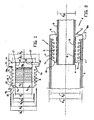
- the half 4 of the cylindrical sealing or sealing body 44 is made of EPDM with a Shore-A hardness of 75 degrees.
- the sealing half 4 comprises a casing (half) 5 with an internal external main diameter of D1 (in this example 34 mm) and with at the one end an end flange 6 extending radially outwards with an outer diameter of D2 (in this example 61 mm) and with at the other end a narrowed end portion 15, which has a diameter of D3 (in this example 45 mm), which is a little smaller than diameter D4 (in this example 48 mm) of the rest of the casing 5.
- the end portion 15 changes into a primary first circumferential rib 7a, which -as seen in the drawing- has a radial annular plane 9a oriented to the left, as well as a radial annular plane 10 oriented to the right, in which the annular plane 9a changes into radial annular plane 10 via inclined ascending annular plane 11 and convex annular plane 12.
- the circumferential rib 7a has a diameter D5 (in this example 55 mm).
- circumferential rib 7a Behind the circumferential rib 7a a series of substantially identical circumferential ribs 7 are integrally formed on the casing 5, which circumferential ribs are situated at equal distances from each other and have a diameter D6 (in this example 57 mm) which is a little larger than D5.
- D6 in this example 57 mm
- the far right circumferential rib 7b has a relatively narrow radial annular plane 10b, which ends in thickened casing portion 13 with diameter D7 (a little larger than D4, in this example 51 mm), which connects the circumferential rib 7b to the end flange 6.
- the circumferential ribs 7a, 7, 7b have a thickness of approximately 4 mm and extend 4 and 5 mm, respectively, from the casing 5 to the outside. They are flexible to such an extent, that some bending in the direction T is possible.
- convex circumferential ribs 8 are integrally formed, which have an inner diameter of D8.
- the far left circumferential rib 8 is situated at a distance of S2 (in this example 10 mm) from the left end of the casing 5 and in the same radial area as the far left circumferential rib 7 but one.
- the far left circumferential rib 7a is situated at a distance of S1 from the left end of the casing 5, which amounts to approximately half S2 (in this example 5 mm).
- a special circumferential rib 8a is integrally formed on the inner plane of the casing 5, which rib has an inclined ascending annular plane 14 and a circumferential axial (namely extending in axial direction, as shown) annular abutment plane 16, which ends in the radial end plane 17 of the end flange 6.
- the circumferential rib 8a is substantially shape-retaining because of the material and in its width or either its low height, namely rigidly against bending in axial direction of the line which the rib 8a will abut, so that the abutment plane 16 will abut the outer surface of the pipe 3 tightly and level.
- two sealing halves 4 are arranged in the annular space 18 formed between coaxially inter-engaging pipe ends 2 and 3 in order to form sealing assembly 1.
- the inner diameter D11 of pipe 2 and the outer diameter D10 of pipe 3 are smaller than D5 and larger than D8, respectively.
- D2 is almost the same as the outer diameter D9 of the pipe 2.
- the circumferential ribs 7a, 7, 7b will be bent backwards as a result of contact with the inner surface of the widest pipe 2, and be pressed against it with their surfaces 11. This is promoted by the presence of the circumferential ribs 8.
- the sealing halves 4 When the sealing halves 4 are inserted so far that the end flange 6 abuts the end edge of the pipe 2, the sealing 4 will not only have sealed the leakage paths A and B, but as a result of circumferential rib 8a with the abutment plane 16 pressed against the pipe 3 and because of the thickened portion 13 which keeps the end flange 6 against the pipe end edge, also a leakage path along C and D will be prevented to a large extent.
- pipe 3 can also be a (thicker) cable, and instead of pipe 2 a passage in a wall (wall, floor, roof) can be formed, through which the (then continuing) line 3 extends.
Landscapes
- Engineering & Computer Science (AREA)
- General Engineering & Computer Science (AREA)
- Mechanical Engineering (AREA)
- Physics & Mathematics (AREA)
- Fluid Mechanics (AREA)
- Gasket Seals (AREA)
- Discharge Heating (AREA)
- Pens And Brushes (AREA)
- Laying Of Electric Cables Or Lines Outside (AREA)
Claims (14)
- Dispositif d'étanchéité assemblé en forme de manchon (1, 4) pour rendre étanche l'espace annulaire (18) entre deux corps (2, 3) se chevauchant partiellement et comprenant des parois de diamètre différent, comme deux tuyaux ou une conduite et un passage dans une paroi pour la conduite, dans lequel le dispositif d'étanchéité comprend un boîtier cylindrique (5) ayant un axe et composé de deux éléments longitudinaux similaires ou plus et une aile d'extrémité (6) formé à une première extrémité du boîtier, qui sont destinés à être logés dans l'espace annulaire et placés contre le rebord d'extrémité du tuyau ou de la conduite (2) le plus large, respectivement le boîtier étant muni sur sa surface extérieure d'un certain nombre de premières nervures périphériques (7) espacées les unes des autres dans la direction axiale, et étant muni sur sa surface intérieure d'un certain nombre de deuxièmes nervures périphériques (8) espacées les unes des autres dans la direction axiale, caractérisé en ce qu'une deuxième nervure périphérique finale (8a) est sensiblement indéformable et est formée sur ladite première extrémité du boîtier sur la circonférence intérieure de l'aile d'extrémité (6), ladite nervure étant munie d'un plan de butée annulaire périphérique (16) s'étendant dans le sens axial destiné à buter contre la conduite ou le tuyau étroit, dans lequel, avant l'utilisation, la deuxième nervure périphérique finale (8a) a une hauteur radiale plus grande dans le plan d'extrémité (17) de l'aile (6), formant ainsi une barrière dans le plan d'extrémité de l'aile durant l'utilisation, dans lequel le plan d'extrémité (17) de l'aile d'extrémité a une forme légèrement conique en pente vers le bord extérieur.
- Dispositif d'étanchéité assemblé en forme de manchon selon la revendication 1, dans lequel la deuxième nervure périphérique finale (8a) a un plan pilote incliné (14) faisant face à l'autre extrémité.
- Dispositif d'étanchéité assemblé en forme de manchon selon l'une quelconque des revendications précédentes, dans lequel le boîtier (5) entre l'aile d'extrémité (6) et la première nervure périphérique (7b) située devant lui a une épaisseur radiale plus grande qu'entre les autres premières nervures périphériques (7).
- Dispositif d'étanchéité assemblé en forme de manchon selon l'une quelconque des revendications précédentes, dans lequel l'autre extrémité (15) du boîtier est rétrécie par rapport au reste du boîtier et est sensiblement cylindrique.
- Dispositif d'étanchéité assemblé en forme de manchon selon la revendication 4, dans lequel la portion rétrécie (15) s'étend depuis l'autre extrémité vers la première nervure périphérique suivante (7a).
- Dispositif d'étanchéité assemblé en forme de manchon selon la revendication 4 ou 5, dans lequel la première nervure périphérique primaire (7a) située le plus près de l'autre extrémité (15) du boîtier s'étend vers un niveau radial plus bas par rapport à la ligne centrale du boîtier cylindrique que les premières nervures périphériques (7) secondaires suivantes.
- Dispositif d'étanchéité assemblé en forme de manchon selon l'une quelconque des revendications précédentes, dans lequel la deuxième nervure périphérique (8) située le plus près de l'autre extrémité du boîtier se trouve à une certaine distance de ladite autre extrémité (15) qui est plus grande que la distance entre ladite autre extrémité et la première nervure périphérique (7a) située le plus près de ladite autre extrémité.
- Dispositif d'étanchéité assemblé en forme de manchon selon la revendication 7, dans lequel ladite deuxième nervure périphérique (8) est au moins presque alignée dans le sens radial avec la première nervure périphérique (7a) secondaire opposée.
- Dispositif d'étanchéité assemblé en forme de manchon selon l'une quelconque des revendications précédentes, dans lequel les premières nervures périphériques (7) sont formées d'un premier plan annulaire (9a) orienté dans le sens axial faisant face à l'autre extrémité (15) du boîtier, d'un deuxième plan annulaire (10) orienté dans le sens axial faisant face à la première extrémité et d'une surface extérieure (11, 12) orientée dans le sens radial reliant ces plans l'un à l'autre, dans lequel le deuxième plan annulaire s'étend dans le sens radial au-delà du premier plan annulaire.
- Dispositif d'étanchéité assemblé en forme de manchon selon la revendication 9, dans lequel la surface extérieure orientée dans le sens radial comprend une portion inclinée (11) faisant face à l'autre extrémité (15).
- Dispositif d'étanchéité assemblé en forme de manchon selon les revendications 9 et 10, dans lequel la surface extérieure orientée dans le sens radial (12) a une forme sensiblement convexe en section transversale axiale.
- Dispositif d'étanchéité assemblé en forme de manchon selon l'une quelconque des revendications précédentes, dans lequel au moins certaines des deuxièmes nervures périphériques (8) forment une surface intérieure convexe orientée dans le sens radial.
- Dispositif d'étanchéité assemblé en forme de manchon selon l'une quelconque des revendications précédentes, constitué d'un caoutchouc synthétique ayant une dureté Shore A de 70 degrés ou plus environ.
- Ensemble de deux corps (2, 3) ayant des parois de diamètre différent qui se rencontrent de manière coaxiale pour définir un espace annulaire devant être rendu étanche, comme deux tuyaux de diamètre différent ou une conduite et un passage dans une paroi pour la conduite, caractérisé en ce que l'espace annulaire est rendu étanche au moyen d'un dispositif d'étanchéité assemblé en forme de manchon (1, 4) selon l'une quelconque des revendications précédentes, dans lequel le diamètre extérieur des premières nervures périphériques (7) et le diamètre intérieur des deuxièmes nervures périphériques (8) sont ajustés sur le diamètre extérieur du tuyau ou de la conduite (3) le plus petit et le diamètre intérieur du tuyau ou du passage dans la paroi (2) le plus grand, de sorte que en pressant contre la paroi concernée du tuyau ou passage le plus grand, les nervures périphériques sont serrées de manière étanche.
Priority Applications (1)
| Application Number | Priority Date | Filing Date | Title |
|---|---|---|---|
| DE69911137T DE69911137T3 (de) | 1998-10-16 | 1999-10-13 | Zusammengesetzte, hülsenförmige Dichtungsvorrichtung |
Applications Claiming Priority (2)
| Application Number | Priority Date | Filing Date | Title |
|---|---|---|---|
| NL1010333A NL1010333C2 (nl) | 1998-10-16 | 1998-10-16 | Samengesteld hulsvormig afdichtingsmiddel. |
| NL1010333 | 1998-10-16 |
Publications (3)
| Publication Number | Publication Date |
|---|---|
| EP0994287A1 EP0994287A1 (fr) | 2000-04-19 |
| EP0994287B1 EP0994287B1 (fr) | 2003-09-10 |
| EP0994287B2 true EP0994287B2 (fr) | 2011-01-26 |
Family
ID=19767972
Family Applications (1)
| Application Number | Title | Priority Date | Filing Date |
|---|---|---|---|
| EP99203324A Expired - Lifetime EP0994287B2 (fr) | 1998-10-16 | 1999-10-13 | Dispositif d'étanchéité composite en forme de manchon |
Country Status (6)
| Country | Link |
|---|---|
| EP (1) | EP0994287B2 (fr) |
| AT (1) | ATE249598T1 (fr) |
| DE (1) | DE69911137T3 (fr) |
| DK (1) | DK0994287T3 (fr) |
| ES (1) | ES2207116T3 (fr) |
| NL (1) | NL1010333C2 (fr) |
Cited By (1)
| Publication number | Priority date | Publication date | Assignee | Title |
|---|---|---|---|---|
| US11365833B2 (en) | 2017-03-02 | 2022-06-21 | Hauff-Technik Gmbh & Co. Kg | Press seal system for sealing against a line |
Families Citing this family (22)
| Publication number | Priority date | Publication date | Assignee | Title |
|---|---|---|---|---|
| NL1016749C2 (nl) * | 2000-11-30 | 2002-05-31 | Beele Eng Bv | Afdichtsysteem. |
| DE20103785U1 (de) * | 2001-03-05 | 2001-08-09 | DTS-PRO-SYS GmbH, 18107 Rostock | Dichtungsmanschette |
| NL1023688C2 (nl) * | 2003-06-18 | 2004-12-21 | Beele Eng Bv | Systeem voor het afdichten van een ruimte tussen een binnenwand van een buisvormige opening en tenminste een althans voor een deel in de opening opgenomen buis of leiding waarvan de as in hoofdzaak evenwijdig is aan de as van de opening. |
| DE202006012463U1 (de) * | 2006-08-12 | 2007-12-27 | Rehau Ag + Co. | Abdeckungsvorrichtung |
| DE202006012464U1 (de) * | 2006-08-12 | 2007-12-27 | Rehau Ag + Co. | Abdeckungsvorrichtung |
| GB0706259D0 (en) * | 2007-03-30 | 2007-05-09 | Thermomax Ltd | Solar collector |
| EP2372208B1 (fr) * | 2010-03-25 | 2013-05-29 | Tenaris Connections Limited | Joint fileté avec bride de joint élastomère |
| GB2503880B (en) * | 2012-07-09 | 2019-03-13 | Polypipe Ltd | Insert for pipes |
| EP2976562A1 (fr) * | 2013-03-22 | 2016-01-27 | Ngi A/S | Accouplement et son utilisation |
| JP6454853B2 (ja) * | 2013-11-30 | 2019-01-23 | 丸一株式会社 | 配管用継手及び配管用継手を用いた配管の施工方法 |
| CH710028A1 (de) * | 2014-08-27 | 2016-02-29 | Brugg Rohr Ag Holding | Gehäuseanordnung für eine Rohrverbindung sowie Verfahren und Dichtung zum Schutz von Rohrverbindungen. |
| DE102014119582B4 (de) * | 2014-12-23 | 2016-10-27 | Wedi Gmbh | Dichteinsatz für einen Wasserablauf |
| DE102014119584B3 (de) * | 2014-12-23 | 2016-05-19 | Wedi Gmbh | Dichteinsatz für einen Wasserablauf |
| US20170081937A1 (en) * | 2015-09-23 | 2017-03-23 | Weatherford Technology Holdings, Llc | Downhole seal |
| CN107697464B (zh) * | 2017-08-22 | 2019-07-23 | 武汉船用机械有限责任公司 | 一种轴管与双油管的防护装置及方法 |
| WO2019183378A1 (fr) * | 2018-03-21 | 2019-09-26 | Phoenix Environmental, Inc. | Joint d'étanchéité sur l'interstice d'un tuyau en fibre de verre à double paroi |
| CN108488380A (zh) * | 2018-04-27 | 2018-09-04 | 北京洛科瀚科技有限公司 | 一种双硬度波纹式橡胶密封圈 |
| DE102019110322A1 (de) * | 2019-04-18 | 2020-10-22 | Wedi Gmbh | Ablaufvorrichtung mit einem Adapter zum Anschluss an eine Rohrleitung |
| EP3952044A1 (fr) * | 2020-08-04 | 2022-02-09 | Hauff-Technik GmbH & Co. KG | Utilisation d'une pièce de raccordement |
| DE102021127568A1 (de) * | 2021-10-22 | 2023-04-27 | Zf Active Safety Gmbh | Verbindungsvorrichtung für einen dichten Austausch von Fluid zwischen zwei Bauteilen, Verbindungssystem und Bremssystem |
| CN114440030A (zh) * | 2022-03-18 | 2022-05-06 | 美得彼餐饮设备(青岛)有限公司 | 一种油炸炉设备及其排放管路、管道连接结构 |
| JP7787537B1 (ja) * | 2025-01-30 | 2025-12-17 | 六菱ゴム株式会社 | 配管の封止プラグ |
Citations (8)
| Publication number | Priority date | Publication date | Assignee | Title |
|---|---|---|---|---|
| CH247518A (de) † | 1944-02-22 | 1947-03-15 | Pfister & Langhanss | Elastischer Dichtungskörper für Rohrverbindungen. |
| DE1475807A1 (de) † | 1965-08-19 | 1969-09-18 | Ruehle Dipl Ing Alfred | Verbindungs- und Dichtungselement fuer Rohrverbindungen |
| DE2203370A1 (de) † | 1972-01-25 | 1973-08-02 | Heinz Wunderlich | Vorrichtung zum verankern von rohrleitungsaustritten in der wand |
| FR2169219A1 (fr) † | 1972-01-25 | 1973-09-07 | Wunderlich Heinz | |
| US4735440A (en) † | 1985-07-05 | 1988-04-05 | Rasmussen Gmbh | Hose coupling |
| US4915422A (en) † | 1989-01-06 | 1990-04-10 | The American Brass & Iron Foundry | Pipe coupling |
| EP0448924B1 (fr) † | 1990-03-28 | 1994-07-06 | Lenzing Aktiengesellschaft | Procédé de séparation de l'eau d'une solution aqueuse diluée de N-méthylmorpholine-N-oxyde, N-méthylmorpholine et/ou morpholine |
| US5653542A (en) † | 1994-05-25 | 1997-08-05 | Brother Kogyo Kabushiki Kaisha | Tape cassette |
Family Cites Families (5)
| Publication number | Priority date | Publication date | Assignee | Title |
|---|---|---|---|---|
| GB1083451A (en) * | 1963-03-11 | 1967-09-13 | Allied Ironfounders Ltd | A sealing member and a pipe joint incorporating the same |
| GB1059749A (en) * | 1964-05-28 | 1967-02-22 | Bibby Foundry Ltd | Pipe seal |
| NL7500337A (en) * | 1975-01-10 | 1976-07-13 | Kleinhof Ferd | Lavatory pan flush pipe union sleeve - is plastic with end flange and internal and external sealing ribs |
| NL177516C (nl) * | 1978-09-12 | 1985-10-01 | Pidou Bv | Afdichtmanchet. |
| EP0139337A3 (fr) * | 1983-10-19 | 1986-07-30 | Pidou B.V. | Système de joint à plusieurs parties |
-
1998
- 1998-10-16 NL NL1010333A patent/NL1010333C2/nl not_active IP Right Cessation
-
1999
- 1999-10-13 DE DE69911137T patent/DE69911137T3/de not_active Expired - Lifetime
- 1999-10-13 AT AT99203324T patent/ATE249598T1/de not_active IP Right Cessation
- 1999-10-13 EP EP99203324A patent/EP0994287B2/fr not_active Expired - Lifetime
- 1999-10-13 ES ES99203324T patent/ES2207116T3/es not_active Expired - Lifetime
- 1999-10-13 DK DK99203324T patent/DK0994287T3/da active
Patent Citations (8)
| Publication number | Priority date | Publication date | Assignee | Title |
|---|---|---|---|---|
| CH247518A (de) † | 1944-02-22 | 1947-03-15 | Pfister & Langhanss | Elastischer Dichtungskörper für Rohrverbindungen. |
| DE1475807A1 (de) † | 1965-08-19 | 1969-09-18 | Ruehle Dipl Ing Alfred | Verbindungs- und Dichtungselement fuer Rohrverbindungen |
| DE2203370A1 (de) † | 1972-01-25 | 1973-08-02 | Heinz Wunderlich | Vorrichtung zum verankern von rohrleitungsaustritten in der wand |
| FR2169219A1 (fr) † | 1972-01-25 | 1973-09-07 | Wunderlich Heinz | |
| US4735440A (en) † | 1985-07-05 | 1988-04-05 | Rasmussen Gmbh | Hose coupling |
| US4915422A (en) † | 1989-01-06 | 1990-04-10 | The American Brass & Iron Foundry | Pipe coupling |
| EP0448924B1 (fr) † | 1990-03-28 | 1994-07-06 | Lenzing Aktiengesellschaft | Procédé de séparation de l'eau d'une solution aqueuse diluée de N-méthylmorpholine-N-oxyde, N-méthylmorpholine et/ou morpholine |
| US5653542A (en) † | 1994-05-25 | 1997-08-05 | Brother Kogyo Kabushiki Kaisha | Tape cassette |
Cited By (1)
| Publication number | Priority date | Publication date | Assignee | Title |
|---|---|---|---|---|
| US11365833B2 (en) | 2017-03-02 | 2022-06-21 | Hauff-Technik Gmbh & Co. Kg | Press seal system for sealing against a line |
Also Published As
| Publication number | Publication date |
|---|---|
| EP0994287B1 (fr) | 2003-09-10 |
| DK0994287T3 (da) | 2004-01-05 |
| ES2207116T3 (es) | 2004-05-16 |
| DE69911137D1 (de) | 2003-10-16 |
| DE69911137T2 (de) | 2004-07-08 |
| DE69911137T3 (de) | 2011-07-21 |
| NL1010333C2 (nl) | 2000-04-18 |
| EP0994287A1 (fr) | 2000-04-19 |
| ATE249598T1 (de) | 2003-09-15 |
Similar Documents
| Publication | Publication Date | Title |
|---|---|---|
| EP0994287B2 (fr) | Dispositif d'étanchéité composite en forme de manchon | |
| US5662360A (en) | Interlocked restraint for a plastic pipe joining system | |
| US6126209A (en) | Pipe having an in-line bell | |
| US4702502A (en) | Gasket for making joints in corrugated plastic pipe | |
| US6488319B2 (en) | Self restrained pressure gasket | |
| US6352288B1 (en) | Thrust and torque resistant pipe joint | |
| AU658127B2 (en) | Secondarily contained fluid supply system | |
| US5490694A (en) | Threadless pipe coupler | |
| US20070273107A1 (en) | System for sealing a space between a tubular opening and a tube | |
| CN113454384B (zh) | 管道组件隔热和蒸汽屏障 | |
| CA2466605C (fr) | Tube comprenant une tulipe etanche en ligne | |
| US5671955A (en) | Threadless pipe coupler for sprinkler pipe | |
| CN216948806U (zh) | 一种地下室用防水穿墙套管结构 | |
| ITRM970555A1 (it) | Giunto ad accoppiamento rapido per connettere un tubo flessibile di piccolo diametro interno ad un tubo metallico di un impianto frenante | |
| US6615860B2 (en) | Fire block conduit coupler | |
| US7104574B2 (en) | Corrugated pipe connection joint | |
| WO1993020381A1 (fr) | Tuyau de refection interne pour canalisations | |
| WO1999040355A1 (fr) | Tuyaux pour fluide a contention par emboitement et cordon | |
| EP1655528B1 (fr) | Élément de liaison entre la cuvette des toilettes et le tuyau de descente. | |
| EP0439313B1 (fr) | Raccords de tuyaux, connexions et pièces de cela | |
| EP1352191B1 (fr) | Raccord de conduit coupe-feu | |
| KR200331508Y1 (ko) | 관 연결장치 | |
| GB2376510A (en) | Pipe connector with means for visual inspection | |
| AU2002224707A1 (en) | Fire block conduit coupler | |
| HK1061423B (en) | Fire block conduit coupler |
Legal Events
| Date | Code | Title | Description |
|---|---|---|---|
| PUAI | Public reference made under article 153(3) epc to a published international application that has entered the european phase |
Free format text: ORIGINAL CODE: 0009012 |
|
| AK | Designated contracting states |
Kind code of ref document: A1 Designated state(s): AT BE CH CY DE DK ES FI FR GB GR IE IT LI LU MC NL PT SE |
|
| AX | Request for extension of the european patent |
Free format text: AL;LT;LV;MK;RO;SI |
|
| 17P | Request for examination filed |
Effective date: 20000810 |
|
| AKX | Designation fees paid |
Free format text: AT BE CH CY DE DK ES FI FR GB GR IE IT LI LU MC NL PT SE |
|
| 17Q | First examination report despatched |
Effective date: 20020416 |
|
| GRAH | Despatch of communication of intention to grant a patent |
Free format text: ORIGINAL CODE: EPIDOS IGRA |
|
| GRAS | Grant fee paid |
Free format text: ORIGINAL CODE: EPIDOSNIGR3 |
|
| GRAA | (expected) grant |
Free format text: ORIGINAL CODE: 0009210 |
|
| AK | Designated contracting states |
Kind code of ref document: B1 Designated state(s): AT BE CH CY DE DK ES FI FR GB GR IE IT LI LU MC NL PT SE |
|
| REG | Reference to a national code |
Ref country code: GB Ref legal event code: FG4D |
|
| REG | Reference to a national code |
Ref country code: CH Ref legal event code: EP |
|
| PG25 | Lapsed in a contracting state [announced via postgrant information from national office to epo] |
Ref country code: IE Free format text: LAPSE BECAUSE OF NON-PAYMENT OF DUE FEES Effective date: 20031013 Ref country code: CY Free format text: LAPSE BECAUSE OF FAILURE TO SUBMIT A TRANSLATION OF THE DESCRIPTION OR TO PAY THE FEE WITHIN THE PRESCRIBED TIME-LIMIT Effective date: 20031013 |
|
| REF | Corresponds to: |
Ref document number: 69911137 Country of ref document: DE Date of ref document: 20031016 Kind code of ref document: P |
|
| REG | Reference to a national code |
Ref country code: IE Ref legal event code: FG4D |
|
| PG25 | Lapsed in a contracting state [announced via postgrant information from national office to epo] |
Ref country code: MC Free format text: LAPSE BECAUSE OF NON-PAYMENT OF DUE FEES Effective date: 20031031 |
|
| PG25 | Lapsed in a contracting state [announced via postgrant information from national office to epo] |
Ref country code: GR Free format text: LAPSE BECAUSE OF FAILURE TO SUBMIT A TRANSLATION OF THE DESCRIPTION OR TO PAY THE FEE WITHIN THE PRESCRIBED TIME-LIMIT Effective date: 20031210 |
|
| REG | Reference to a national code |
Ref country code: CH Ref legal event code: NV Representative=s name: DR. R.C. SALGO EUROPEAN PATENT ATTORNEY |
|
| PG25 | Lapsed in a contracting state [announced via postgrant information from national office to epo] |
Ref country code: PT Free format text: LAPSE BECAUSE OF FAILURE TO SUBMIT A TRANSLATION OF THE DESCRIPTION OR TO PAY THE FEE WITHIN THE PRESCRIBED TIME-LIMIT Effective date: 20031218 |
|
| REG | Reference to a national code |
Ref country code: DK Ref legal event code: T3 |
|
| REG | Reference to a national code |
Ref country code: SE Ref legal event code: TRGR |
|
| REG | Reference to a national code |
Ref country code: ES Ref legal event code: FG2A Ref document number: 2207116 Country of ref document: ES Kind code of ref document: T3 |
|
| PLBQ | Unpublished change to opponent data |
Free format text: ORIGINAL CODE: EPIDOS OPPO |
|
| PLBI | Opposition filed |
Free format text: ORIGINAL CODE: 0009260 |
|
| ET | Fr: translation filed | ||
| PLAX | Notice of opposition and request to file observation + time limit sent |
Free format text: ORIGINAL CODE: EPIDOSNOBS2 |
|
| REG | Reference to a national code |
Ref country code: IE Ref legal event code: MM4A |
|
| 26 | Opposition filed |
Opponent name: BEELE ENGINEERING B.V Effective date: 20040609 |
|
| NLR1 | Nl: opposition has been filed with the epo |
Opponent name: BEELE ENGINEERING B.V |
|
| PLAX | Notice of opposition and request to file observation + time limit sent |
Free format text: ORIGINAL CODE: EPIDOSNOBS2 |
|
| PLBB | Reply of patent proprietor to notice(s) of opposition received |
Free format text: ORIGINAL CODE: EPIDOSNOBS3 |
|
| PLAQ | Examination of admissibility of opposition: information related to despatch of communication + time limit deleted |
Free format text: ORIGINAL CODE: EPIDOSDOPE2 |
|
| PLAR | Examination of admissibility of opposition: information related to receipt of reply deleted |
Free format text: ORIGINAL CODE: EPIDOSDOPE4 |
|
| PLBQ | Unpublished change to opponent data |
Free format text: ORIGINAL CODE: EPIDOS OPPO |
|
| PLAB | Opposition data, opponent's data or that of the opponent's representative modified |
Free format text: ORIGINAL CODE: 0009299OPPO |
|
| R26 | Opposition filed (corrected) |
Opponent name: BEELE ENGINEERING B.V Effective date: 20040609 |
|
| RAP2 | Party data changed (patent owner data changed or rights of a patent transferred) |
Owner name: ARTECH RUBBER B.V. |
|
| NLR1 | Nl: opposition has been filed with the epo |
Opponent name: BEELE ENGINEERING B.V |
|
| PGFP | Annual fee paid to national office [announced via postgrant information from national office to epo] |
Ref country code: CH Payment date: 20050929 Year of fee payment: 7 |
|
| PGFP | Annual fee paid to national office [announced via postgrant information from national office to epo] |
Ref country code: FR Payment date: 20050930 Year of fee payment: 7 |
|
| PGFP | Annual fee paid to national office [announced via postgrant information from national office to epo] |
Ref country code: DK Payment date: 20051004 Year of fee payment: 7 |
|
| PGFP | Annual fee paid to national office [announced via postgrant information from national office to epo] |
Ref country code: SE Payment date: 20051005 Year of fee payment: 7 Ref country code: FI Payment date: 20051005 Year of fee payment: 7 |
|
| PGFP | Annual fee paid to national office [announced via postgrant information from national office to epo] |
Ref country code: GB Payment date: 20051012 Year of fee payment: 7 Ref country code: BE Payment date: 20051012 Year of fee payment: 7 |
|
| PGFP | Annual fee paid to national office [announced via postgrant information from national office to epo] |
Ref country code: ES Payment date: 20051017 Year of fee payment: 7 |
|
| PGFP | Annual fee paid to national office [announced via postgrant information from national office to epo] |
Ref country code: AT Payment date: 20051018 Year of fee payment: 7 |
|
| PGFP | Annual fee paid to national office [announced via postgrant information from national office to epo] |
Ref country code: LU Payment date: 20051027 Year of fee payment: 7 |
|
| PLAB | Opposition data, opponent's data or that of the opponent's representative modified |
Free format text: ORIGINAL CODE: 0009299OPPO |
|
| PLAB | Opposition data, opponent's data or that of the opponent's representative modified |
Free format text: ORIGINAL CODE: 0009299OPPO |
|
| R26 | Opposition filed (corrected) |
Opponent name: BEELE ENGINEERING B.V Effective date: 20040609 |
|
| NLR1 | Nl: opposition has been filed with the epo |
Opponent name: BEELE ENGINEERING B.V |
|
| PG25 | Lapsed in a contracting state [announced via postgrant information from national office to epo] |
Ref country code: FI Free format text: LAPSE BECAUSE OF NON-PAYMENT OF DUE FEES Effective date: 20061013 Ref country code: AT Free format text: LAPSE BECAUSE OF NON-PAYMENT OF DUE FEES Effective date: 20061013 |
|
| PG25 | Lapsed in a contracting state [announced via postgrant information from national office to epo] |
Ref country code: SE Free format text: LAPSE BECAUSE OF NON-PAYMENT OF DUE FEES Effective date: 20061014 |
|
| PG25 | Lapsed in a contracting state [announced via postgrant information from national office to epo] |
Ref country code: LI Free format text: LAPSE BECAUSE OF NON-PAYMENT OF DUE FEES Effective date: 20061031 Ref country code: DK Free format text: LAPSE BECAUSE OF NON-PAYMENT OF DUE FEES Effective date: 20061031 Ref country code: CH Free format text: LAPSE BECAUSE OF NON-PAYMENT OF DUE FEES Effective date: 20061031 |
|
| PGFP | Annual fee paid to national office [announced via postgrant information from national office to epo] |
Ref country code: IT Payment date: 20061031 Year of fee payment: 8 |
|
| APBP | Date of receipt of notice of appeal recorded |
Free format text: ORIGINAL CODE: EPIDOSNNOA2O |
|
| APAH | Appeal reference modified |
Free format text: ORIGINAL CODE: EPIDOSCREFNO |
|
| APBQ | Date of receipt of statement of grounds of appeal recorded |
Free format text: ORIGINAL CODE: EPIDOSNNOA3O |
|
| REG | Reference to a national code |
Ref country code: CH Ref legal event code: PL |
|
| EUG | Se: european patent has lapsed | ||
| GBPC | Gb: european patent ceased through non-payment of renewal fee |
Effective date: 20061013 |
|
| REG | Reference to a national code |
Ref country code: FR Ref legal event code: ST Effective date: 20070629 |
|
| PG25 | Lapsed in a contracting state [announced via postgrant information from national office to epo] |
Ref country code: GB Free format text: LAPSE BECAUSE OF NON-PAYMENT OF DUE FEES Effective date: 20061013 |
|
| BERE | Be: lapsed |
Owner name: *ARTECH RUBBER B.V. Effective date: 20061031 |
|
| REG | Reference to a national code |
Ref country code: ES Ref legal event code: FD2A Effective date: 20061014 |
|
| PG25 | Lapsed in a contracting state [announced via postgrant information from national office to epo] |
Ref country code: FR Free format text: LAPSE BECAUSE OF NON-PAYMENT OF DUE FEES Effective date: 20061031 Ref country code: ES Free format text: LAPSE BECAUSE OF NON-PAYMENT OF DUE FEES Effective date: 20061014 |
|
| PG25 | Lapsed in a contracting state [announced via postgrant information from national office to epo] |
Ref country code: LU Free format text: LAPSE BECAUSE OF NON-PAYMENT OF DUE FEES Effective date: 20061013 |
|
| PG25 | Lapsed in a contracting state [announced via postgrant information from national office to epo] |
Ref country code: IT Free format text: LAPSE BECAUSE OF NON-PAYMENT OF DUE FEES Effective date: 20071013 Ref country code: BE Free format text: LAPSE BECAUSE OF FAILURE TO SUBMIT A TRANSLATION OF THE DESCRIPTION OR TO PAY THE FEE WITHIN THE PRESCRIBED TIME-LIMIT Effective date: 20061031 |
|
| APBU | Appeal procedure closed |
Free format text: ORIGINAL CODE: EPIDOSNNOA9O |
|
| PLAH | Information related to despatch of examination report in opposition + time limit modified |
Free format text: ORIGINAL CODE: EPIDOSCORE2 |
|
| PLAY | Examination report in opposition despatched + time limit |
Free format text: ORIGINAL CODE: EPIDOSNORE2 |
|
| PLBC | Reply to examination report in opposition received |
Free format text: ORIGINAL CODE: EPIDOSNORE3 |
|
| PLAT | Information related to reply to examination report in opposition deleted |
Free format text: ORIGINAL CODE: EPIDOSDORE3 |
|
| PLBC | Reply to examination report in opposition received |
Free format text: ORIGINAL CODE: EPIDOSNORE3 |
|
| PLAY | Examination report in opposition despatched + time limit |
Free format text: ORIGINAL CODE: EPIDOSNORE2 |
|
| PLBC | Reply to examination report in opposition received |
Free format text: ORIGINAL CODE: EPIDOSNORE3 |
|
| PUAH | Patent maintained in amended form |
Free format text: ORIGINAL CODE: 0009272 |
|
| STAA | Information on the status of an ep patent application or granted ep patent |
Free format text: STATUS: PATENT MAINTAINED AS AMENDED |
|
| 27A | Patent maintained in amended form |
Effective date: 20110126 |
|
| AK | Designated contracting states |
Kind code of ref document: B2 Designated state(s): AT BE CH CY DE DK ES FI FR GB GR IE IT LI LU MC NL PT SE |
|
| REG | Reference to a national code |
Ref country code: NL Ref legal event code: T3 |
|
| PGFP | Annual fee paid to national office [announced via postgrant information from national office to epo] |
Ref country code: NL Payment date: 20161005 Year of fee payment: 18 Ref country code: DE Payment date: 20161018 Year of fee payment: 18 |
|
| REG | Reference to a national code |
Ref country code: DE Ref legal event code: R119 Ref document number: 69911137 Country of ref document: DE |
|
| REG | Reference to a national code |
Ref country code: NL Ref legal event code: MM Effective date: 20171101 |
|
| PG25 | Lapsed in a contracting state [announced via postgrant information from national office to epo] |
Ref country code: NL Free format text: LAPSE BECAUSE OF NON-PAYMENT OF DUE FEES Effective date: 20171101 Ref country code: DE Free format text: LAPSE BECAUSE OF NON-PAYMENT OF DUE FEES Effective date: 20180501 |