EP0995545A2 - Appareil de preréglage d'un outil - Google Patents
Appareil de preréglage d'un outil Download PDFInfo
- Publication number
- EP0995545A2 EP0995545A2 EP99120380A EP99120380A EP0995545A2 EP 0995545 A2 EP0995545 A2 EP 0995545A2 EP 99120380 A EP99120380 A EP 99120380A EP 99120380 A EP99120380 A EP 99120380A EP 0995545 A2 EP0995545 A2 EP 0995545A2
- Authority
- EP
- European Patent Office
- Prior art keywords
- tool
- rotation
- length measuring
- machining
- calibration
- Prior art date
- Legal status (The legal status is an assumption and is not a legal conclusion. Google has not performed a legal analysis and makes no representation as to the accuracy of the status listed.)
- Granted
Links
Images


Classifications
-
- B—PERFORMING OPERATIONS; TRANSPORTING
- B23—MACHINE TOOLS; METAL-WORKING NOT OTHERWISE PROVIDED FOR
- B23Q—DETAILS, COMPONENTS, OR ACCESSORIES FOR MACHINE TOOLS, e.g. ARRANGEMENTS FOR COPYING OR CONTROLLING; MACHINE TOOLS IN GENERAL CHARACTERISED BY THE CONSTRUCTION OF PARTICULAR DETAILS OR COMPONENTS; COMBINATIONS OR ASSOCIATIONS OF METAL-WORKING MACHINES, NOT DIRECTED TO A PARTICULAR RESULT
- B23Q17/00—Arrangements for observing, indicating or measuring on machine tools
- B23Q17/24—Arrangements for observing, indicating or measuring on machine tools using optics or electromagnetic waves
- B23Q17/2452—Arrangements for observing, indicating or measuring on machine tools using optics or electromagnetic waves for measuring features or for detecting a condition of machine parts, tools or workpieces
- B23Q17/2457—Arrangements for observing, indicating or measuring on machine tools using optics or electromagnetic waves for measuring features or for detecting a condition of machine parts, tools or workpieces of tools
-
- G—PHYSICS
- G01—MEASURING; TESTING
- G01B—MEASURING LENGTH, THICKNESS OR SIMILAR LINEAR DIMENSIONS; MEASURING ANGLES; MEASURING AREAS; MEASURING IRREGULARITIES OF SURFACES OR CONTOURS
- G01B11/00—Measuring arrangements characterised by the use of optical techniques
- G01B11/02—Measuring arrangements characterised by the use of optical techniques for measuring length, width or thickness
- G01B11/028—Measuring arrangements characterised by the use of optical techniques for measuring length, width or thickness by measuring lateral position of a boundary of the object
-
- G—PHYSICS
- G05—CONTROLLING; REGULATING
- G05B—CONTROL OR REGULATING SYSTEMS IN GENERAL; FUNCTIONAL ELEMENTS OF SUCH SYSTEMS; MONITORING OR TESTING ARRANGEMENTS FOR SUCH SYSTEMS OR ELEMENTS
- G05B19/00—Program-control systems
- G05B19/02—Program-control systems electric
- G05B19/18—Numerical control [NC], i.e. automatically operating machines, in particular machine tools, e.g. in a manufacturing environment, so as to execute positioning, movement or co-ordinated operations by means of program data in numerical form
- G05B19/401—Numerical control [NC], i.e. automatically operating machines, in particular machine tools, e.g. in a manufacturing environment, so as to execute positioning, movement or co-ordinated operations by means of program data in numerical form characterised by control arrangements for measuring, e.g. calibration and initialisation, measuring workpiece for machining purposes
-
- G—PHYSICS
- G05—CONTROLLING; REGULATING
- G05B—CONTROL OR REGULATING SYSTEMS IN GENERAL; FUNCTIONAL ELEMENTS OF SUCH SYSTEMS; MONITORING OR TESTING ARRANGEMENTS FOR SUCH SYSTEMS OR ELEMENTS
- G05B2219/00—Program-control systems
- G05B2219/30—Nc systems
- G05B2219/37—Measurements
- G05B2219/37572—Camera, tv, vision
-
- G—PHYSICS
- G05—CONTROLLING; REGULATING
- G05B—CONTROL OR REGULATING SYSTEMS IN GENERAL; FUNCTIONAL ELEMENTS OF SUCH SYSTEMS; MONITORING OR TESTING ARRANGEMENTS FOR SUCH SYSTEMS OR ELEMENTS
- G05B2219/00—Program-control systems
- G05B2219/30—Nc systems
- G05B2219/45—Nc applications
- G05B2219/45145—Milling
-
- G—PHYSICS
- G05—CONTROLLING; REGULATING
- G05B—CONTROL OR REGULATING SYSTEMS IN GENERAL; FUNCTIONAL ELEMENTS OF SUCH SYSTEMS; MONITORING OR TESTING ARRANGEMENTS FOR SUCH SYSTEMS OR ELEMENTS
- G05B2219/00—Program-control systems
- G05B2219/30—Nc systems
- G05B2219/50—Machine tool, machine tool null till machine tool work handling
- G05B2219/50139—Calibration, setting tool after measurement on tool
-
- G—PHYSICS
- G05—CONTROLLING; REGULATING
- G05B—CONTROL OR REGULATING SYSTEMS IN GENERAL; FUNCTIONAL ELEMENTS OF SUCH SYSTEMS; MONITORING OR TESTING ARRANGEMENTS FOR SUCH SYSTEMS OR ELEMENTS
- G05B2219/00—Program-control systems
- G05B2219/30—Nc systems
- G05B2219/50—Machine tool, machine tool null till machine tool work handling
- G05B2219/50294—Tool offset length by going to a reference and recording distance
Definitions
- the invention relates to a device for measuring a machine tool using machining tool, in particular a cutting tool, with a tool holder for holding the tool in a predetermined arrangement in with respect to a length measuring device scanning the tool for the detection of Positions of machining elements provided on the tool.
- the tool holder is rotatable.
- One connected to the tool holder Tool that is to be measured and adjusted is turned using the tool holder, the tool being cut by the length measuring device on its cutting tool supporting scope is scanned.
- the length measuring device determines the radial one Position of the cutting edges, i.e. their distance from the working axis of rotation of the tool, where the working axis of rotation in a predetermined position with respect to the length measuring device is arranged.
- you can use such a device e.g. the cutting edge positions of a drill can also be measured.
- the invention creates a new device for tool presetting by means of correcting the influence of errors on deviations in the tool position marked by the given arrangement on the detection of the positions is.
- the correction device comprises a calibration device for pre-determination and storage of deviation values, the calibration device a calibration tool, preferably with predetermined setting positions of the processing elements corresponding touch points for length measurement.
- the length measuring device is preferably an optical length measuring device with a device for image processing.
- the length measuring device includes an electronic camera and / or a laser triangulator.
- the processing tool is a Rotation about a working axis of rotation provided rotary tool, in particular a Milling tool with cutting edges as adjustable processing elements.
- the correction device for correcting the influence of errors is based on the previously determined Deviations in the position of the working axis of rotation of the rotary tool from a predetermined one Axis position provided.
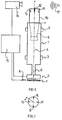
- the bearing 2 and 3 rotatable about an axis 4 to not shown Parts of the device is stored.
- a rotary drive 5 is used to rotate the tool holder 1.
- a drive shaft 6 of the rotary drive 5 is connected to a turntable 7, the one on the peripheral edge by a sensor has detectable division.
- an optical sensor 8 detected a line division.
- the reference numeral 9 denotes a front recess coaxial to the axis of rotation 4 of the im present embodiment cylindrical tool holder 1.
- a milling tool 10 with a conical end part is used in the conical end recess 8.
- the milling tool 10 has four cutting edges 11 to 14 arranged at an angular distance of 90 ° from one another on.
- the cutting edges 11 to 14 are adjustable in their holders, so that the cutting edges be arranged at a desired distance from the working axis of rotation of the milling tool 9 can.
- the working axis of rotation of the milling tool 10 coincides with the axis of rotation 4 of the tool holder 1 together, insofar as there is a manufacturing tolerance of the tool holder slight deviations in position of these axes of rotation can result from each other.
- the optical sensor 8 is equipped with an evaluation and control device comprising a microprocessor 15 in connection, via which u.a. the rotary drive 5 can be controlled.
- An electronic camera 16 is also connected to the evaluation and control device 15 in FIG the field of vision of which has the cutting edges 11 to 14 end part of the milling tool 10 Arrangement comes.
- the camera 16 detects the measurement object in the backlight.
- FIG. 3 differs from the embodiment of FIG. 1 and 2 only in that a laser triangulator 18 is used for measuring the length corresponding to a double arrow 19 parallel to an axis of rotation 4a of a tool holder 1a is displaceable.
- the evaluation and control device 15 contains an image processing program suitable for determining lengths, which, as can be seen from FIG. 4a, is based on a predetermined target position y 0 of the working axis of rotation of the milling tool 10 on a Y coordinate.
- the camera 16 detects a limitation of the measurement object in the y direction.
- the image processing program determines a coordinate value y r.
- the position of the working axis of rotation of the tool 15, 15a can deviate from the axis of rotation 4, 4a of the tool holder 1, 1a.
- the cylinder axis of the tool holder 1, 1a need not coincide with its axis of rotation. Overall, these deviations ultimately result in the working axis of rotation of the tool rotated with the tool holder moving about the axis of rotation of the tool holder.
- the working axis of rotation of the tool 10, 10a which is relevant for determining the distance r is shifted by ⁇ x 0 ( ⁇ ) or ⁇ y 0 ( ⁇ ) from the position x 0, y 0.
- a calibration with the aid of a calibration tool with known distances r 0 of the cutting edges from the working axis of rotation and / or with a known tool diameter must be carried out before using the presetting device.
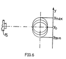
- the reference position y 0 or x 0 corresponding to the axis of rotation 4, 4a of the tool holder 1, 1a is determined, which is explained below with reference to FIG. 6, which relates to the exemplary embodiment of FIGS. 1 and 2.
- the tool holder is rotated to determine the reference value y 0 , the maximum values of the deflection y max and y min, between which an angle of rotation ⁇ of 180 ° lies, being determined.
- correction values ⁇ y 0 as a function of the rotational angle position ⁇ of the tool holder can be determined and stored in a calibration run under control of the drive 5 by the device 15 as a function of the rotational angle position ⁇ of the tool holder.
- intermediate values y m lying between the maximum value y max and zero are determined as a function of ⁇ .
- the device calibrated in this way can automatically make corrections when measuring setting values undertake, the evaluation and control device the respective rotational position angle ⁇ of the tool holder is determined and based on the stored, the rotational angle positions ⁇ assigned correction values corrected automatically measured setting values so that they correspond exactly to the distances of the cutting edges from the working axis of rotation of the tool.
- the tool to be set does not need to be specific to the tool holder Angular position to be clamped in the tool holder. Decisive for the correction is only the angle of rotation of the tool holder.
- measured values could be used for the determination of correction values below the cutting elements, also on the tool holder become.
- the calibration tool itself does not need to have cutting edges like the tool. It could only be formed by a shaft with a known diameter.
Landscapes
- Engineering & Computer Science (AREA)
- Physics & Mathematics (AREA)
- General Physics & Mathematics (AREA)
- Human Computer Interaction (AREA)
- Manufacturing & Machinery (AREA)
- Automation & Control Theory (AREA)
- Optics & Photonics (AREA)
- Mechanical Engineering (AREA)
- Machine Tool Sensing Apparatuses (AREA)
- Numerical Control (AREA)
- Automatic Control Of Machine Tools (AREA)
- Length Measuring Devices By Optical Means (AREA)
Applications Claiming Priority (2)
| Application Number | Priority Date | Filing Date | Title |
|---|---|---|---|
| DE19848079 | 1998-10-19 | ||
| DE1998148079 DE19848079A1 (de) | 1998-10-19 | 1998-10-19 | Vorrichtung zur Werkzeugvoreinstellung |
Publications (3)
| Publication Number | Publication Date |
|---|---|
| EP0995545A2 true EP0995545A2 (fr) | 2000-04-26 |
| EP0995545A3 EP0995545A3 (fr) | 2002-04-03 |
| EP0995545B1 EP0995545B1 (fr) | 2007-03-07 |
Family
ID=7884903
Family Applications (1)
| Application Number | Title | Priority Date | Filing Date |
|---|---|---|---|
| EP19990120380 Revoked EP0995545B1 (fr) | 1998-10-19 | 1999-10-13 | Appareil de preréglage d'un outil |
Country Status (3)
| Country | Link |
|---|---|
| EP (1) | EP0995545B1 (fr) |
| DE (2) | DE19848079A1 (fr) |
| ES (1) | ES2284231T3 (fr) |
Cited By (1)
| Publication number | Priority date | Publication date | Assignee | Title |
|---|---|---|---|---|
| CN101628388A (zh) * | 2008-07-14 | 2010-01-20 | 罗伯特.博世有限公司 | 用于对工具机进行校准的装置 |
Families Citing this family (3)
| Publication number | Priority date | Publication date | Assignee | Title |
|---|---|---|---|---|
| DE102006011814A1 (de) * | 2006-03-15 | 2007-09-20 | E. Zoller Gmbh & Co. Kg | Werkzeugmessgerät zur Vermessung eines Werkzeugs in einem Werkzeughalter und Werkzeughalter |
| WO2008082422A1 (fr) * | 2007-01-05 | 2008-07-10 | General Electric Company | Procédé d'alignement d'outil de coupe |
| US9245062B2 (en) | 2012-03-22 | 2016-01-26 | Virtek Vision International Inc. | Laser projection system using variable part alignment |
Family Cites Families (11)
| Publication number | Priority date | Publication date | Assignee | Title |
|---|---|---|---|---|
| DE2138366C2 (de) * | 1971-07-31 | 1973-04-05 | Wohlhaupter E & Co | Vorrichtung zum voreinstellen und nachprüfen der einstellung der messerschneiden rotierender, insbesondere bohr-,dreh- und fräswerkzeuge |
| FR2544855B1 (fr) * | 1983-04-20 | 1986-02-21 | Snecma | Procede et dispositif de mesure de precision de la hauteur des aubes d'un rotor |
| DE8601152U1 (de) * | 1986-01-18 | 1986-07-03 | Sitzmann & Heinlein GmbH, 90513 Zirndorf | Meßvorrichtung |
| GB2200747B (en) * | 1986-12-23 | 1990-10-17 | Kenneth Geoffrey Swift | Improvements in tool identification and condition monitoring |
| AU597485B2 (en) * | 1987-04-22 | 1990-05-31 | John Lysaght (Australia) Limited | Non-contact determination of the position of a rectilinear feature of an article |
| US4966460A (en) * | 1987-10-28 | 1990-10-30 | The Ingersoll Milling Machine Company | Laser gauging of rotary cutting tools |
| DE3743717A1 (de) * | 1987-12-23 | 1989-07-06 | Alfred Dipl Ing Spitzley | Optoelektronische messvorrichtung zur automatischen vermessung der werkzeugschneidkantenlage mit handelsueblichen werkzeugvoreinstellgeraeten |
| DE3811551A1 (de) * | 1988-04-06 | 1989-10-19 | Peter Herkt | Einstellgeraet fuer eine werkzeugmaschine |
| DE3905949A1 (de) * | 1989-02-25 | 1990-08-30 | Herbert Prof Dr Ing Schulz | Verfahren zum vermessen von schneidkanten |
| DE19629616C2 (de) * | 1996-07-23 | 1998-05-07 | Heilig & Schwab Gmbh | Vorrichtung und Verfahren zum manuellen Einstellen, Messen, ggf. Prüfen von Werkzeugen für Bearbeitungsmaschinen |
| DE19632148A1 (de) * | 1996-08-09 | 1998-02-12 | Gfe Ges Fuer Fertigungstechnik | Maschinenwerkzeug für die Prozeßsteuerung |
-
1998
- 1998-10-19 DE DE1998148079 patent/DE19848079A1/de not_active Withdrawn
-
1999
- 1999-10-13 EP EP19990120380 patent/EP0995545B1/fr not_active Revoked
- 1999-10-13 DE DE59914236T patent/DE59914236D1/de not_active Expired - Lifetime
- 1999-10-13 ES ES99120380T patent/ES2284231T3/es not_active Expired - Lifetime
Cited By (2)
| Publication number | Priority date | Publication date | Assignee | Title |
|---|---|---|---|---|
| CN101628388A (zh) * | 2008-07-14 | 2010-01-20 | 罗伯特.博世有限公司 | 用于对工具机进行校准的装置 |
| CN101628388B (zh) * | 2008-07-14 | 2014-12-10 | 罗伯特.博世有限公司 | 用于对工具机进行校准的装置 |
Also Published As
| Publication number | Publication date |
|---|---|
| DE19848079A1 (de) | 2000-04-20 |
| DE59914236D1 (de) | 2007-04-19 |
| EP0995545B1 (fr) | 2007-03-07 |
| EP0995545A3 (fr) | 2002-04-03 |
| ES2284231T3 (es) | 2007-11-01 |
Similar Documents
| Publication | Publication Date | Title |
|---|---|---|
| EP2834595B1 (fr) | Méthode et appareil pour la réduction des erreurs associées à un dispositif de rotation lors de la détermination des coordonnées d'une pièce ou lors de l'usinage d'une pièce | |
| DE4238504C2 (de) | Verfahren zum Vermessen eines Werkzeuges | |
| DE102018105877B3 (de) | Vorrichtung für die Bestimmung einer Ausrichtung einer optischen Vorrichtung eines Kohärenztomographen, Kohärenztomograph und Laserbearbeitungssystem | |
| EP0520396B1 (fr) | Mesure automatique d'un outil | |
| EP2668464B1 (fr) | Dispositif de réglage et/ou de mesure | |
| DE4420137A1 (de) | Meßgerät zur Überprüfung der Abmessungen von zylindrischen Werkstücken | |
| WO2010130420A1 (fr) | Dispositif et procédé permettant de déterminer la position et l'orientation | |
| DE3900491A1 (de) | Messeinrichtung fuer eine rundschleifmaschine | |
| EP1698855A1 (fr) | Procédé et dispositif destinés à l'ajustage de machines, d'éléments de machines ou d'autres objets techniques | |
| EP1236971B1 (fr) | Procédé et dispositif pour la détermination de l'orientation axiale de deux axes de machines | |
| EP1834730A1 (fr) | Appareil de mesure d'outil destiné à la mesure d'un outil dans un support d'outil et support d'outil | |
| DE10322587B4 (de) | Verfahren und Vorrichtung zur Herstellung von Referenzflächen an Fassungen optischer Elemente durch eine spanende Bearbeitung sowie damit hergestellte optische Elemente | |
| DE4030994A1 (de) | Pruefeinrichtung fuer rotationssymmetrische werkstuecke | |
| EP0734305B1 (fr) | Procede pour le reglage d'alesoirs et outils analogues | |
| EP1071924A1 (fr) | Procede de mesure laser destine a determiner l'azimut, l'elevation et l'ecart de deux broches d'outil par rapport a un plan de reference | |
| DE102009036013A1 (de) | Verfahren zur Bearbeitung von Werkstücken | |
| EP0771406B1 (fr) | Dispositif et procede de mesure et de calcul de parametres geometriques d'un corps | |
| DE3320983A1 (de) | Transportables geraet zur pruefung des zahnflankenprofils und der zahnflankenlinien (zahnschraege) von zahnraedern auf verzahnmaschinen oder zahnflankenschleifmaschinen sowie zur positionierung dieses geraetes und zum orientieren des messtasters an der verzahnung fuer den messvorgang | |
| EP0995545B1 (fr) | Appareil de preréglage d'un outil | |
| EP2194359A2 (fr) | Méthode et dispositif pour mesurer le bord des lentilles optiques | |
| DE102019134660A1 (de) | Verfahren zum Ermitteln eines Ausgangspunktes einer Werkzeugmaschine und eines Werkzeugmagazins | |
| EP3760981B1 (fr) | Dispositif de mesure d'angle et procédé de fonctionnement d'un dispositif de mesure d'angle | |
| DE1473931A1 (de) | Einrichtung zur fortwaehrenden Ermittlung der Istlage eines beweglichen Geraetes in einem Bezugskoordinatensystem | |
| DE102010011634B3 (de) | Verfahren zum Vermessen der Schneidengeometrie von Fräswerkzeugen | |
| DE102019104604A1 (de) | Verfahren zum Bestimmen einer Topographie einer Werkzeugmaschine |
Legal Events
| Date | Code | Title | Description |
|---|---|---|---|
| PUAI | Public reference made under article 153(3) epc to a published international application that has entered the european phase |
Free format text: ORIGINAL CODE: 0009012 |
|
| AK | Designated contracting states |
Kind code of ref document: A2 Designated state(s): AT BE CH CY DE DK ES FI FR GB GR IE IT LI LU MC NL PT SE Kind code of ref document: A2 Designated state(s): DE ES FR GB IT SE |
|
| AX | Request for extension of the european patent |
Free format text: AL;LT;LV;MK;RO;SI |
|
| PUAL | Search report despatched |
Free format text: ORIGINAL CODE: 0009013 |
|
| RIC1 | Information provided on ipc code assigned before grant |
Free format text: 7G 01B 11/02 A, 7B 23Q 17/09 B, 7B 23Q 17/22 B, 7B 23Q 17/24 B |
|
| AK | Designated contracting states |
Kind code of ref document: A3 Designated state(s): AT BE CH CY DE DK ES FI FR GB GR IE IT LI LU MC NL PT SE |
|
| AX | Request for extension of the european patent |
Free format text: AL;LT;LV;MK;RO;SI |
|
| 17P | Request for examination filed |
Effective date: 20020926 |
|
| AKX | Designation fees paid |
Free format text: DE ES FR GB IT SE |
|
| GRAP | Despatch of communication of intention to grant a patent |
Free format text: ORIGINAL CODE: EPIDOSNIGR1 |
|
| GRAS | Grant fee paid |
Free format text: ORIGINAL CODE: EPIDOSNIGR3 |
|
| GRAA | (expected) grant |
Free format text: ORIGINAL CODE: 0009210 |
|
| AK | Designated contracting states |
Kind code of ref document: B1 Designated state(s): DE ES FR GB IT SE |
|
| REG | Reference to a national code |
Ref country code: GB Ref legal event code: FG4D Free format text: NOT ENGLISH |
|
| REF | Corresponds to: |
Ref document number: 59914236 Country of ref document: DE Date of ref document: 20070419 Kind code of ref document: P |
|
| REG | Reference to a national code |
Ref country code: SE Ref legal event code: TRGR |
|
| GBT | Gb: translation of ep patent filed (gb section 77(6)(a)/1977) |
Effective date: 20070529 |
|
| ET | Fr: translation filed | ||
| REG | Reference to a national code |
Ref country code: ES Ref legal event code: FG2A Ref document number: 2284231 Country of ref document: ES Kind code of ref document: T3 |
|
| PLBI | Opposition filed |
Free format text: ORIGINAL CODE: 0009260 |
|
| PLAX | Notice of opposition and request to file observation + time limit sent |
Free format text: ORIGINAL CODE: EPIDOSNOBS2 |
|
| 26 | Opposition filed |
Opponent name: E. ZOLLER GMBH & CO. KG Effective date: 20071207 |
|
| PLAF | Information modified related to communication of a notice of opposition and request to file observations + time limit |
Free format text: ORIGINAL CODE: EPIDOSCOBS2 |
|
| PLBB | Reply of patent proprietor to notice(s) of opposition received |
Free format text: ORIGINAL CODE: EPIDOSNOBS3 |
|
| RDAF | Communication despatched that patent is revoked |
Free format text: ORIGINAL CODE: EPIDOSNREV1 |
|
| PGFP | Annual fee paid to national office [announced via postgrant information from national office to epo] |
Ref country code: ES Payment date: 20111027 Year of fee payment: 13 |
|
| APAH | Appeal reference modified |
Free format text: ORIGINAL CODE: EPIDOSCREFNO |
|
| APBM | Appeal reference recorded |
Free format text: ORIGINAL CODE: EPIDOSNREFNO |
|
| APBP | Date of receipt of notice of appeal recorded |
Free format text: ORIGINAL CODE: EPIDOSNNOA2O |
|
| APBQ | Date of receipt of statement of grounds of appeal recorded |
Free format text: ORIGINAL CODE: EPIDOSNNOA3O |
|
| APBU | Appeal procedure closed |
Free format text: ORIGINAL CODE: EPIDOSNNOA9O |
|
| PGFP | Annual fee paid to national office [announced via postgrant information from national office to epo] |
Ref country code: SE Payment date: 20130430 Year of fee payment: 14 Ref country code: GB Payment date: 20130430 Year of fee payment: 14 Ref country code: DE Payment date: 20130430 Year of fee payment: 14 |
|
| PGFP | Annual fee paid to national office [announced via postgrant information from national office to epo] |
Ref country code: IT Payment date: 20130430 Year of fee payment: 14 Ref country code: FR Payment date: 20130604 Year of fee payment: 14 |
|
| REG | Reference to a national code |
Ref country code: DE Ref legal event code: R082 Ref document number: 59914236 Country of ref document: DE Representative=s name: PATENTANWAELTE BERNHARDT/WOLFF PARTNERSCHAFT M, DE Ref country code: DE Ref legal event code: R082 Ref document number: 59914236 Country of ref document: DE Representative=s name: PATENTANWAELTE BERNHARDT/WOLFF PARTNERSCHAFT, DE |
|
| REG | Reference to a national code |
Ref country code: SE Ref legal event code: EUG |
|
| GBPC | Gb: european patent ceased through non-payment of renewal fee |
Effective date: 20131013 |
|
| PG25 | Lapsed in a contracting state [announced via postgrant information from national office to epo] |
Ref country code: GB Free format text: LAPSE BECAUSE OF NON-PAYMENT OF DUE FEES Effective date: 20131013 |
|
| REG | Reference to a national code |
Ref country code: FR Ref legal event code: ST Effective date: 20140630 |
|
| REG | Reference to a national code |
Ref country code: DE Ref legal event code: R119 Ref document number: 59914236 Country of ref document: DE Effective date: 20140501 |
|
| PG25 | Lapsed in a contracting state [announced via postgrant information from national office to epo] |
Ref country code: SE Free format text: LAPSE BECAUSE OF NON-PAYMENT OF DUE FEES Effective date: 20131014 Ref country code: IT Free format text: LAPSE BECAUSE OF NON-PAYMENT OF DUE FEES Effective date: 20131013 Ref country code: FR Free format text: LAPSE BECAUSE OF NON-PAYMENT OF DUE FEES Effective date: 20131031 Ref country code: DE Free format text: LAPSE BECAUSE OF NON-PAYMENT OF DUE FEES Effective date: 20140501 |
|
| RDAD | Information modified related to despatch of communication that patent is revoked |
Free format text: ORIGINAL CODE: EPIDOSCREV1 |
|
| REG | Reference to a national code |
Ref country code: ES Ref legal event code: FD2A Effective date: 20150401 |
|
| PG25 | Lapsed in a contracting state [announced via postgrant information from national office to epo] |
Ref country code: ES Free format text: LAPSE BECAUSE OF NON-PAYMENT OF DUE FEES Effective date: 20131014 |
|
| RDAG | Patent revoked |
Free format text: ORIGINAL CODE: 0009271 |
|
| STAA | Information on the status of an ep patent application or granted ep patent |
Free format text: STATUS: PATENT REVOKED |
|
| 27W | Patent revoked |
Effective date: 20141218 |
|
| REG | Reference to a national code |
Ref country code: SE Ref legal event code: ECNC |