EP0995584A1 - Reifenwulstwickelvorrichtung und verfahren - Google Patents
Reifenwulstwickelvorrichtung und verfahren Download PDFInfo
- Publication number
- EP0995584A1 EP0995584A1 EP99912123A EP99912123A EP0995584A1 EP 0995584 A1 EP0995584 A1 EP 0995584A1 EP 99912123 A EP99912123 A EP 99912123A EP 99912123 A EP99912123 A EP 99912123A EP 0995584 A1 EP0995584 A1 EP 0995584A1
- Authority
- EP
- European Patent Office
- Prior art keywords
- bead wire
- support body
- winding
- wire
- bead
- Prior art date
- Legal status (The legal status is an assumption and is not a legal conclusion. Google has not performed a legal analysis and makes no representation as to the accuracy of the status listed.)
- Granted
Links
- 239000011324 bead Substances 0.000 title claims abstract description 136
- 238000004804 winding Methods 0.000 title claims abstract description 106
- 238000000034 method Methods 0.000 title claims description 12
- 238000000465 moulding Methods 0.000 claims abstract description 63
- 210000000078 claw Anatomy 0.000 claims abstract description 20
- 238000006073 displacement reaction Methods 0.000 claims description 19
- 238000002407 reforming Methods 0.000 claims description 7
- 238000003825 pressing Methods 0.000 claims description 5
- 238000010586 diagram Methods 0.000 description 6
- 238000013459 approach Methods 0.000 description 4
- 230000003247 decreasing effect Effects 0.000 description 3
- 230000006835 compression Effects 0.000 description 2
- 238000007906 compression Methods 0.000 description 2
- 229910000831 Steel Inorganic materials 0.000 description 1
- 230000015572 biosynthetic process Effects 0.000 description 1
- 230000009133 cooperative interaction Effects 0.000 description 1
- 230000006866 deterioration Effects 0.000 description 1
- 230000000694 effects Effects 0.000 description 1
- 238000004519 manufacturing process Methods 0.000 description 1
- 230000002093 peripheral effect Effects 0.000 description 1
- 238000000926 separation method Methods 0.000 description 1
- 239000010959 steel Substances 0.000 description 1
- 238000003860 storage Methods 0.000 description 1
Images


Classifications
-
- B—PERFORMING OPERATIONS; TRANSPORTING
- B29—WORKING OF PLASTICS; WORKING OF SUBSTANCES IN A PLASTIC STATE IN GENERAL
- B29D—PRODUCING PARTICULAR ARTICLES FROM PLASTICS OR FROM SUBSTANCES IN A PLASTIC STATE
- B29D30/00—Producing pneumatic or solid tyres or parts thereof
- B29D30/06—Pneumatic tyres or parts thereof (e.g. produced by casting, moulding, compression moulding, injection moulding, centrifugal casting)
- B29D30/48—Bead-rings or bead-cores; Treatment thereof prior to building the tyre
-
- B—PERFORMING OPERATIONS; TRANSPORTING
- B29—WORKING OF PLASTICS; WORKING OF SUBSTANCES IN A PLASTIC STATE IN GENERAL
- B29D—PRODUCING PARTICULAR ARTICLES FROM PLASTICS OR FROM SUBSTANCES IN A PLASTIC STATE
- B29D30/00—Producing pneumatic or solid tyres or parts thereof
- B29D30/06—Pneumatic tyres or parts thereof (e.g. produced by casting, moulding, compression moulding, injection moulding, centrifugal casting)
- B29D30/08—Building tyres
- B29D30/10—Building tyres on round cores, i.e. the shape of the core is approximately identical with the shape of the completed tyre
- B29D30/18—Fitting the bead-rings or bead-cores; Folding the textile layers around the rings or cores
-
- B—PERFORMING OPERATIONS; TRANSPORTING
- B29—WORKING OF PLASTICS; WORKING OF SUBSTANCES IN A PLASTIC STATE IN GENERAL
- B29D—PRODUCING PARTICULAR ARTICLES FROM PLASTICS OR FROM SUBSTANCES IN A PLASTIC STATE
- B29D30/00—Producing pneumatic or solid tyres or parts thereof
- B29D30/06—Pneumatic tyres or parts thereof (e.g. produced by casting, moulding, compression moulding, injection moulding, centrifugal casting)
- B29D30/48—Bead-rings or bead-cores; Treatment thereof prior to building the tyre
- B29D2030/487—Forming devices for manufacturing the beads
Definitions
- This invention relates to a bead wire winding device which can be suitably applied in order to directly wind and dispose a bead wire at a predetermined position of a tire during molding on a rotatable molding support body.
- a bead wire is arranged at a predetermined position of a tire side portion during molding.
- This positioning is normally performed by attaching a bead ring, which is wound and formed in advance in a ring shape of a predetermined dimension by a bead fabricating device, to a side portion of a tire by a manual operation of an operator or by using a device called a bead setter.
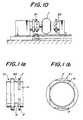
- a conventional bead setter shown in a perspective view of Fig. 10, sets a plurality of bead rings in each side portion of a tire during molding.
- This conventional bead setter sets two circular bead rings or more, which have the same diameter and are formed of steel cords, in advance at predetermined positions of each side portion during molding of a heavy load-use tire used for a truck, bus, or the like.
- each bead ring Prior to setting, each bead ring is engaged and held by a manual operation of an operator at the tip of cylinder setters S1 and S2, respectively, which approach and withdraw from respective side portions of a tire T in a horizontal direction during molding.
- an external diameter of the tire T becomes larger than an internal diameter of the bead ring from the beginning of the molding or during the molding. Therefore, particularly, prior to molding a tire, it is necessary to hold or support a predetermined number of bead rings, for example two bead rings, in advance on the cylinder setter S1 which is arranged in a rotary driving portion of the tire T. Because of this, in a conventional cylinder setter S1, as shown in an enlarged perspective view and a plan view of Figs.
- a tip holding portion H which has an external diameter substantially equal to an internal diameter of a bead ring is provided to engage the first bead ring that is initially set at a side portion of the tire T.
- a space SK is provided to temporarily store a second bead ring which is set next. This space SK is positioned behind two diametrically opposed flanges F, at upper and lower positions in the figure.
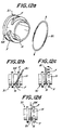
- FIG. 12a arrangement of the second bead ring to the space SK is shown in Fig. 12a.
- a bead ring B1 is elastically deformed in a substantially longitudinally elliptical shape.
- the lower end portion is passed around the lower side of the lower end side of the flange F and engaged in a notch N disposed under the space SK, as shown in Fig. 12b.
- the upper end portion of the bead ring B1 is made to pass over and behind the top end side of the flange F, as shown in Fig. 12c.
- An object of this invention is to provide a bead wire winding device which can accurately arrange a bead wire at a predetermined position with few operations without increasing equipment cost and causing undesired plastic deformation to a bead wire.
- Another object is to eliminate the need to pre-manufacture and store various types of bead rings in which a bead wire is wound and formed in a ring shape, and to completely eliminate the need for space and numerous operations to sort or store the bead wires.
- a bead wire winding device of this invention is provided with a molding support body connected to a rotational shaft, a winding guide(s) which is rotated with the molding support body, and which approachingly and retreatingly displaces with respect to each side portion of the molding support body and enlargingly and reducingly deforms, and a wire supply means which supplies a bead wire to a wire seating portion of the winding guide within a space defined by each winding guide which is in an approached state with respect to a respective side surface of the molding support body, and in an enlarged diameter state.
- the winding guide is constituted by a plurality of radially displacing members, which can be displaced in a radial direction, connected to a boss portion through link members.
- Each of the radially displacing members has a protrusion that is located radially inward an outer periphery of the respective radially displacing member and which forms a wire seating portion. Furthermore, an advance/retreat driving means of a boss portion is disposed that advancingly and retreatingly drives the boss portion with respect to the molding support body.
- a clamping claw is provided on at least one of the radially displacing members, and is urged constantly in a closing direction and pinching a tip portion of the bead wire.
- a driving means is disposed which causes opening displacement of the clamping claw.
- a winding guide is made to approach and be positioned at a side portion of the molding support body.
- a radially displacing member can be constituted by a fan-shaped member or a circular arc-shaped segment, or a rod member, in which a peripheral width is far narrower.
- an advance/retreat driving means of a boss portion and a driving means of a clamping claw are fixed to respective non-rotational side members.
- the weight of rotation members which are rotated and driven with the molding support body can be advantageously decreased, and a power supply structure to the driving means can be simply performed.
- the molding support body can be removed from a rotational axis, and, for example, the molding support body can be separated from the rotational axis while remaining integral with a green tire formed thereon.
- the molding support body can function as-is as an internal surface type within a vulcanizing mold, and a process of separating the green tire from the molding support body is not needed.
- the wire supply means is constituted by a reforming roll which bends and deforms a bead wire which has been fed out, a grooved roll which specifies a winding position of the bead wire after it goes through the reforming roll, and a pressing roll which presses a trailing end portion of the bead wire after it goes through the grooved roll.
- a cutter be disposed to cut a bead wire which has been wound over a predetermined length.
- the wire supply means can be displaced in an axial direction of the rotational axis during the operation.
- the displacement in the axial direction is a displacement with a pitch equivalent to a thickness of the bead wire.
- each radially displacing member of a winding guide in a radial direction can be performed as follows, for example.
- each radially displacing member is slid in a radially outward direction on an inclined cam surface disposed on the rotational axis.
- each radially displacing member is slid in a radially inward direction on the inclined cam surface.
- a base tube that rotates and a boss portion are sequentially arranged on the rotational axis, and the base tube and the boss portion can be mutually independently displaced in an axial direction of the rotational axis.
- a guide means which guides displacement of a radially displacing member in a radial direction for example, a rail and a direct moving guide formed of a slider engaged with the rail, is provided on each radially displacing member, and on a flange disposed at the end portion of a molding support body side, of the base tube.
- this invention proposes a method of winding a bead wire which can be suitably obtained by using a winding device which is structured above.
- a method of winding a bead wire of this invention prior to arranging a bead wire which is made to rest against a side portion of a molding support body, that is, a tire molded on the molding support body, in a radial direction and a circumferential direction, the bead wire is wound a predetermined number of levels on a wire seating portion protruding toward the molding support body of the winding guide within a space defined by the molding support body and the winding guide which is in an approached state with respect to a respective side surface of the molding support body, and in an enlarged diameter state.
- the winding guide is made to be distant from the molding support body in a reduced diameter state and the bead wire is maintained at a required position of the molding support body.
- Fig. 1 is a perspective view showing one embodiment of a bead wire winding device according to this invention.
- 1 is a core body as one example of a molding support body, and this core body 1 has an external ring shape corresponding to an internal shape of a product tire.
- the core body 1 is detachably drivingly coupled to a rotation shaft 2 which is rotated by a driving means, which is not depicted, arranged at the left side of the figure. Furthermore, at each side portion of the core body 1, a winding guide 3 is arranged which is rotated with the core body 1, and which approaches and retreats from the side portion of the core body 1, and which also enlargingly and reducingly deforms.
- rotational movement of the winding guide 3 can be realized as a boss portion of the winding guide 3 is coupled to the rotational shaft 2 by a key, a spline(s), a serration(s), or the like.
- a boss portion of the winding guide 3 is coupled to the rotational shaft 2 by a key, a spline(s), a serration(s), or the like.
- the axial portion 2a protruding from the core body 1 toward the right side of the figure is made to be horizontally displaced in an axial direction integrally with the winding guide 3, so the axial portion 2a can be detachable with respect to the main body portion of the rotational shaft 2.
- peculiar male and female engaging portions for example, are disposed at respective axial ends of the axial portion 2a and the rotational axis main body portion, and the axial portion 2a can be re-engaged by movement in a direction opposite to that in the foregoing explanation with respect to the winding guide 3.
- a pair of cylinders 4 which can be synchronously operated is attached at the fixed member side, preferably at diametrically opposed positions of the rotational shaft 2.
- Fig. 2 is a cross-sectional view showing an upper half portion of this mechanism, above the center axis line.
- the housing 5 is supported by the pair of cylinders 4, which are attached to the fixed member side.
- the rods of a pair of enlarging/reducing cylinders 6, preferably disposed at diametrically opposed positions, are connected to the boss portion 7 of the winding guide 3.
- the winding guide 3 can be approachingly and retreatingly displaced with respect to the core body 1 as needed by the operation of the cylinders 4.
- the rods of the enlarging/reducing cylinders 6 are connected to the boss portion 7, which is rotated with the core body 1, via a thrust bearing or a radial bearing.
- advancing/retreating driving of the boss portion 7 by the cylinders 6 is possible, and free rotation of the boss portion 7 with respect to the cylinder rods is possible.
- the housing 5 connected to the fixed member side via the cylinders 4 is maintained in a non-rotational state.
- the winding guide 3 shown in the figures is structured such that the tip portion of each of the plurality of link members 8 connected to the boss portion 7 are hinge-connected to a plurality of fan-shaped members 9, which are one example of a radial displacing member.
- Diameter enlarging displacement of the winding guide 3 can be performed, based upon advancing displacement of the boss portion 7 effected by the operation of the enlarging/reducing cylinders 6, via a radial direction guide means which allows movement only in reducing and enlarging directions with respect to the rotational shaft 2.
- a protrusion 10 is provided on the side of each fan-shaped member 9 facing the core body 1.
- the protrusion 10 forms a wire seating portion that is positioned radial inward of the outer periphery of the fan-shaped member 9.
- the protrusion 10 forms a wire seating portion 11 along with like protrusions 10 of the other fan-shaped members 9 under the enlarging displacement of the fan-shaped members 9 shown in the upper half portion of Fig. 3a.
- these wire seating portions 11 define a bead wire winding space with a predetermined cross-sectional shape.
- a notch 12 is disposed in a radial direction in the flange 9a of at least one fan-shaped member 9, as shown in Figs. 4a and 4b, which extends to the rear surface side of the protrusion 10 from the outer periphery of the flange 9a.
- a clamping claw 13 which is advancingly and retreatingly displaced in a thickness direction of the fan-shaped members 9 is disposed within the notch 12, and a bead wire tip portion which is inserted to the rear surface side of the protrusion 10 can be pinched and held as the clamping claw 13 advances.
- Fig. 4c is a cross-sectional view showing a state in which a tip portion a bead wire W is pinched and held.
- the clamping claw 13 is constantly urged in an advancing direction, that is, a closing direction, by an elastic means, for example, a compression spring 14, disposed at its rear surface side, the bead wire W is pinched with a predetermined strength between the clamping claw 13 and the rear surface of the protrusion 10.
- releasing the bead wire W that is, opening of the clamping claw 13 after completion of predetermined winding of the bead wire W, can be performed as a rod 17 protruding to the rear surface side of the clamping claw 13 is retreatingly displaced against the spring force of the compression spring 14 by a cylinder 15 attached to a cylindrical portion 5a of the housing 5 as a fixed member, via a hook 16 disposed at the rod end.
- the cylinder 15 is fixed to the housing 5, which is a non-rotational side member, interference between the rod 17 which is rotated and moved along with the winding guide 3 and the rod end hook 16 can be prevented by placing the hook 16 in an advance-restricted position as shown in the figure during non-operation of the cylinder 15, when the hook structure is such as is shown in Fig. 4c.
- FIG. 1 shows a wire supply device that supplies a bead wire to the wire seating portion 11 within the bead wire winding space defined by the side surface of the core body 1 and the winding guide 3 which has approached the side surface of the core body 1 in an enlarged-diameter state.
- this wire supply device 18 includes a reforming roll 19, which causes predetermined bend and deformation of a bead wire W which is fed out, a grooved roll 21 that is displaced in an up-and-down direction in the figure by a cylinder 20, and specifies a winding position of the bead wire W which has passed through the reforming roll 19, a pressure roll 23 which is advancingly and retreatingly displaced in a radial direction of the winding guide 3 by a cylinder 22, and presses the trailing end portion of the bead wire W which has passed through the grooved roll 21, and a cutter 24 disposed between the pressure roll 23 and the grooved roll 21.
- the wire supply device 18 with this structure, or at least the portion of the wire supply device 18 frontward of the reforming roll 19, can be displaced in an axial line direction of the rotational shaft 2 by, for example, a pitch equivalent to a thickness of the bead wire W during operation.
- a device which is thus structured When winding of a bead wire is performed by a device which is thus structured, first, the cylinders 4 are operated, and the winding guide 3 approaches the side surface of the core body 1 along with the housing 5. At the same time, the enlarging/reducing cylinders 6 fixed to the housing 5 are operated, and the radially displacing members, that is, the winding guide 3, that is in the reduced diameter position shown in the upper half portion of Fig. 6a is placed in the enlarged diameter state shown in the lower half portion of Fig. 6a.
- Fig. 6b is a front view of the winding guide 3 showing this, and this shows the case when the radially displacing members of the winding guide 3 are circular arc segments.
- a predetermined bead wire winding space is created between the winding guide 3 and the side surface of the core body 1 by this type of displacement and deformation of the winding guide 3.
- the protruding rod 17 of the clamping claw 13, disposed on a specified circular arc segment, fan-shaped member 9 or the like, and the hook 16 fixed to the cylinder 15 on the housing 5 are placed in corresponding positions as shown in Fig. 4c, so by operating the cylinder 15, the clamping claw 13 is placed in the open state shown in Fig. 7.
- the wire supply device 18 is displaced to a predetermined position with respect to the bead wire winding space, that is, an operating position, and moves the grooved roll 21 down as shown in Fig. 8a.
- the tip portion of the bead wire W is inserted between the clamping claw 13 in an open state and the rear surface of the protrusion 10 in a formed portion of the notch 12 shown in Figs. 4a and 4b.
- the clamping claw 13 is placed in the closed state shown in Fig. 4c, and the bead wire W is pinched between the rear surface of the protrusion 10 and the clamping claw 13 at a predetermined force.
- the core body 1 and the winding guide 3 are rotated and driven as shown in Fig. 8b, and the bead wire W is made to rest against the core body side surface, or, more accurately, against the side surface of the tire during molding, on the wire seating portion 11, and and is wound a predetermined number of levels.
- the grooved roll 21 is gradually retreatingly displaced, that is, displaced in the upward direction in the figure, and the winding radius sequentially increases.
- there are two rows of winding wires or more as shown in a partial cross-sectional view in a radial direction of the core body 1 in Fig.
- winding is performed by, in addition to operating as described above, displacing the grooved roll 21 in the axial line direction for every winding of the bead wire W.
- the rotation of the core body 1 and the winding guide 3, pressing of the winding wire by the pressure roll 23, and raising of the grooved roll 21 shown in Fig. 8d are sequentially stopped. Additionally, the bead wire W is cut off by operating the cutter 24. Additionally, under the operation of the pressure roll 23, based upon the subsequent rotation of the core body 1 for approximately 1-3 rotations, the trailing end portion of the bead wire W is sufficiently crimped to the already-wound portion.
- the wire supply device 18 is returned to the original retreated position, and the winding guide 3 is separatingly displaced from the core body 1 during the opening of the clamping claw 13, in the reduced-diameter state.
- the bead wire W remains as-is at the side portion of the core body 1, and the tire molding operation or the like can be sufficiently smoothly performed.
- the bead wire in a tire formation process, since a bead wire(s) is wound at a predetermined position(s) as needed, the bead wire can be constantly accurately disposed without causing unexpected plastic deformation or the like, increasing equipment cost, and/or increasing the number of operation processes, and the required space and the like can be significantly decreased compared to the prior art.
- Fig. 9 is a schematic cross-sectional view showing an upper half portion, above the center line, of a suitable structural example for enlargingly/reducingly displacing the radially displacing members, for example, fan-shaped members, of the winding guide 3.
- a base tube 31 is inserted between the rotational shaft 2 and the boss portion 7 of the winding guide 3.
- a key, a spline, a serration, or the like By engaging this base tube 31 with the rotational shaft 2 and the boss portion 7 with a key, a spline, a serration, or the like, the rotation of the base tube 31 and the boss portion 7, which is integral with the rotational shaft 2, is maintained, and the base tube 31 and the boss portion 7 can be independently displaced in the axial line direction of the rotational shaft 2.
- a flange 32 is disposed that protrudes in a direction perpendicular to the axial line of the rotational shaft 2.
- a guide means 33 which guides displacement of the fan-shaped members 9 in a radial direction is disposed on this flange 32 and the fan-shaped members 9 that are connected to the boss portion 7 by the link members 8.
- the guide means 33 can be structured by, for example, a rail 34 which is provided extending in a radial direction of the flange 32, and a moving guide formed of a slider 35 which is constantly engaged with the rail 34, and which is disposed directly or indirectly on the fan-shaped members 9. According to the guide means 33 with this type of structure, the position of the fan-shaped members 9 can be restricted to be within a plane perpendicular to the rotational axis.
- the housing 5 of the winding guide 3 is supported by the base tube 31 via a bearing 36, and the burden of the cylinders 4 is decreased compared to the previous case.
- the winding guide 3 and the housing 5 can be integrally displaced in an axial line direction of the rotational shaft 2 in a state in which the winding guide 3 and the housing 5 ride together on the base tube 31, and the base tube 31 and the winding guide 3 can follow as the rotational shaft 2 is rotated. Therefore, needless to say, the same operational effects can be obtained as in the previous case.
- the guide means that guide displacement of the fan-shaped members 9 from the rotational shaft 2 in a radial direction, it is possible to simply and easily attach and remove a device structural member(s) to/from the rotational shaft 2.
- a bead setter to set a tire at a predetermined position during molding of the bead ring is not needed, and, without increasing equipment cost and the number of operations to operate the bead setter, unexpected deformation of the bead wire can be sufficiently eliminated, and accurate and efficient arrangement of the bead wire at a desired position can be realized.
Landscapes
- Engineering & Computer Science (AREA)
- Mechanical Engineering (AREA)
- Tyre Moulding (AREA)
Applications Claiming Priority (5)
| Application Number | Priority Date | Filing Date | Title |
|---|---|---|---|
| JP9479598 | 1998-04-07 | ||
| JP9479598 | 1998-04-07 | ||
| JP4440299 | 1999-02-23 | ||
| JP04440299A JP4230591B2 (ja) | 1998-04-07 | 1999-02-23 | ビードワイヤ巻取装置およびそれの巻取方法 |
| PCT/JP1999/001824 WO1999051424A1 (fr) | 1998-04-07 | 1999-04-06 | Dispositif et procede d'enroulement de fil metallique pour tringles de pneumatique |
Publications (3)
| Publication Number | Publication Date |
|---|---|
| EP0995584A1 true EP0995584A1 (de) | 2000-04-26 |
| EP0995584A4 EP0995584A4 (de) | 2004-03-10 |
| EP0995584B1 EP0995584B1 (de) | 2005-08-24 |
Family
ID=26384305
Family Applications (1)
| Application Number | Title | Priority Date | Filing Date |
|---|---|---|---|
| EP99912123A Expired - Lifetime EP0995584B1 (de) | 1998-04-07 | 1999-04-06 | Reifenwulstwickelvorrichtung und verfahren |
Country Status (6)
| Country | Link |
|---|---|
| US (1) | US6352602B1 (de) |
| EP (1) | EP0995584B1 (de) |
| JP (1) | JP4230591B2 (de) |
| DE (1) | DE69926850T2 (de) |
| ES (1) | ES2247789T3 (de) |
| WO (1) | WO1999051424A1 (de) |
Cited By (2)
| Publication number | Priority date | Publication date | Assignee | Title |
|---|---|---|---|---|
| WO2006003057A1 (de) * | 2004-07-06 | 2006-01-12 | Continental Aktiengesellschaft | Verfahren und vorrichtung zum positionieren von wulstkernen |
| EP2055467A1 (de) * | 2007-11-05 | 2009-05-06 | Hankook Tire Co., Ltd. | Wulststrukturerzeugungsvorrichtung in einer Erzeugungsmaschine für grüne Reifen |
Families Citing this family (24)
| Publication number | Priority date | Publication date | Assignee | Title |
|---|---|---|---|---|
| USD514140S1 (en) * | 2003-11-03 | 2006-01-31 | Bartell Machinery Systems, Llc | Cone unit for tire bead collapsing assembly in a tire bead winding assembly |
| USD503939S1 (en) * | 2003-11-03 | 2005-04-12 | Bartell Machinery Systems, Llc | Frame for a driven let-off stand for use in a tire bead winding assembly |
| USD503414S1 (en) * | 2003-11-03 | 2005-03-29 | Bartell Machinery Systems, Llc | Six segment spindle assembly for use in a tire bead winding assembly |
| USD503940S1 (en) * | 2003-11-03 | 2005-04-12 | Bartell Machinery Systems, Llc | Single segment in a six segment spindle assembly for use in tire bead winding assembly |
| USD504445S1 (en) * | 2003-11-03 | 2005-04-26 | Bartell Machinery Systems, Llc | Wire gripper assembly for tire bead winding assembly |
| USD504139S1 (en) * | 2003-11-03 | 2005-04-19 | Bartell Machinery Systems, Llc | Shaft for driven let-off stand in a tire bead winding assembly |
| USD503727S1 (en) * | 2003-11-03 | 2005-04-05 | Bartell Machinery Systems, Llc | Wire gripping segment of a wire gripping assembly for use in a tire bead winding assembly |
| US20050224158A1 (en) * | 2004-04-01 | 2005-10-13 | Dyrlund Christopher D | Bead construction method and apparatus for a tire |
| WO2006095735A1 (ja) * | 2005-03-09 | 2006-09-14 | Toyo Tire & Rubber Co., Ltd. | ランフラットタイヤの製造方法 |
| JP2007030299A (ja) * | 2005-07-26 | 2007-02-08 | Bridgestone Corp | ピッチ送りローラによるワイヤ配列方法 |
| JP2007276738A (ja) * | 2006-04-11 | 2007-10-25 | Honda Motor Co Ltd | 電線保持装置 |
| US20100288423A1 (en) * | 2006-06-29 | 2010-11-18 | Pirelli Tyre S.P.A. | Process for manufacturing tyres for vehicle wheels |
| WO2009128286A1 (ja) * | 2008-04-14 | 2009-10-22 | 不二精工 株式会社 | ビードワイヤ巻付け成形装置 |
| CN104245179B (zh) | 2012-04-24 | 2016-03-02 | 不二精工株式会社 | 钢丝圈制造装置 |
| WO2013190696A1 (ja) | 2012-06-22 | 2013-12-27 | 不二精工 株式会社 | 巻取り装置 |
| CN103862692B (zh) * | 2014-03-10 | 2016-09-28 | 无锡盛力达科技股份有限公司 | 胎圈钢丝缠绕机绕丝支架 |
| JP5902850B1 (ja) * | 2015-06-10 | 2016-04-13 | 株式会社大塚電業社 | テープ巻き移し冶具 |
| IT201600070310A1 (it) * | 2016-07-06 | 2018-01-06 | Bridgestone Europe Nv | Tamburo rotante a smontaggio rapido per la formazione di un tallone di un pneumatico |
| JP6801285B2 (ja) * | 2016-08-08 | 2020-12-16 | 住友ゴム工業株式会社 | ビードコア製造装置 |
| CN107900264A (zh) * | 2017-12-12 | 2018-04-13 | 中国化工集团曙光橡胶工业研究设计院有限公司 | 一种小规格轮胎钢丝圈卷成装置 |
| CN113834457B (zh) * | 2021-11-26 | 2022-02-22 | 天津赛象科技股份有限公司 | 包布宽度测量方法以及钢丝圈包布缠绕方法 |
| CN115008805B (zh) * | 2022-06-28 | 2024-02-06 | 联亚智能科技(苏州)有限公司 | 用于将异形钢丝直接缠绕成方钢丝圈的装配盘及生产设备 |
| CN116424664B (zh) * | 2023-04-11 | 2025-11-21 | 扬州绿宝人造草坪有限公司 | 一种人造草坪自动打包装置 |
| CN116851596B (zh) * | 2023-09-05 | 2023-11-28 | 海安橡胶集团股份公司 | 一种钢丝圈缠绕盘及钢丝圈缠绕装置 |
Family Cites Families (10)
| Publication number | Priority date | Publication date | Assignee | Title |
|---|---|---|---|---|
| US1423929A (en) * | 1916-06-19 | 1922-07-25 | Fisk Rubber Co | Method of and apparatus for forming a tire bead |
| US1914040A (en) * | 1931-12-24 | 1933-06-13 | Nat Standard Co | Tire construction |
| US1957981A (en) * | 1932-02-29 | 1934-05-08 | Nat Standard Co | Tire building apparatus |
| US2537632A (en) * | 1945-12-10 | 1951-01-09 | Firestone Tire & Rubber Co | Tire |
| LU38371A1 (de) * | 1959-04-03 | |||
| JPS56105948A (en) * | 1980-01-25 | 1981-08-22 | Sumitomo Rubber Ind Ltd | Wirewrap former of lead core wire |
| JPH0262232A (ja) * | 1988-08-29 | 1990-03-02 | Toyo Tire & Rubber Co Ltd | 自動車タイヤのビード部複合構造体の組立方法、その組立装置およびビードフィラー貼合せ装置 |
| IT1237737B (it) * | 1989-12-22 | 1993-06-15 | Siegenthaler Karl J. | Apparato per la realizzazione di talloni, e per l'alimentazione degli stessi ad un tamburo di formatura di pneumatici di autoveicoli. |
| JPH06198766A (ja) | 1992-12-28 | 1994-07-19 | Bridgestone Corp | タイヤ成型法およびその装置 |
| JP3207604B2 (ja) * | 1993-04-01 | 2001-09-10 | 中田エンヂニアリング株式会社 | ビードコア形成装置 |
-
1999
- 1999-02-23 JP JP04440299A patent/JP4230591B2/ja not_active Expired - Fee Related
- 1999-04-06 ES ES99912123T patent/ES2247789T3/es not_active Expired - Lifetime
- 1999-04-06 WO PCT/JP1999/001824 patent/WO1999051424A1/ja not_active Ceased
- 1999-04-06 DE DE69926850T patent/DE69926850T2/de not_active Expired - Fee Related
- 1999-04-06 US US09/424,535 patent/US6352602B1/en not_active Expired - Lifetime
- 1999-04-06 EP EP99912123A patent/EP0995584B1/de not_active Expired - Lifetime
Cited By (4)
| Publication number | Priority date | Publication date | Assignee | Title |
|---|---|---|---|---|
| WO2006003057A1 (de) * | 2004-07-06 | 2006-01-12 | Continental Aktiengesellschaft | Verfahren und vorrichtung zum positionieren von wulstkernen |
| US7699952B2 (en) | 2004-07-06 | 2010-04-20 | Continental Aktiengesellschaft | Method and device for positioning bead wires |
| EP2055467A1 (de) * | 2007-11-05 | 2009-05-06 | Hankook Tire Co., Ltd. | Wulststrukturerzeugungsvorrichtung in einer Erzeugungsmaschine für grüne Reifen |
| CN101428479B (zh) * | 2007-11-05 | 2012-08-22 | 韩国轮胎株式会社 | 生胎成型设备中的胎圈部成型装置 |
Also Published As
| Publication number | Publication date |
|---|---|
| EP0995584A4 (de) | 2004-03-10 |
| EP0995584B1 (de) | 2005-08-24 |
| US6352602B1 (en) | 2002-03-05 |
| DE69926850T2 (de) | 2006-06-29 |
| DE69926850D1 (de) | 2005-09-29 |
| ES2247789T3 (es) | 2006-03-01 |
| JP4230591B2 (ja) | 2009-02-25 |
| JPH11348148A (ja) | 1999-12-21 |
| WO1999051424A1 (fr) | 1999-10-14 |
Similar Documents
| Publication | Publication Date | Title |
|---|---|---|
| US6352602B1 (en) | Bead wire winding device and winding method | |
| KR100982889B1 (ko) | 코일 형성 방법 및 코일 형성 장치 | |
| JPWO2003012962A1 (ja) | モータの製造方法 | |
| US6113833A (en) | Segmented toroidal core for manufacturing pneumatic tires | |
| KR101573305B1 (ko) | 비드 와이어의 권취 및 성형 장치 | |
| EP0492918A2 (de) | Verfahren zum Formen einer Bahn | |
| KR0185749B1 (ko) | 타이어용 비드 조립품의 제조방법 및 그 장치 | |
| JP2003154581A (ja) | タイヤ用ビードコアの製造方法および装置 | |
| EP1297946A2 (de) | Trommel zum Aufbau einer Reifenkarkasse und dieselbe enthaltende Einrichtung | |
| JP4288321B2 (ja) | パイプベンダー、およびパイプ曲げ加工方法 | |
| CN114884286A (zh) | 绕制有铜线的定子瓣的拼装设备 | |
| EP0278892B1 (de) | Vorrichtung zum Aufbauen von Luftreifen | |
| CN215835209U (zh) | 电机铁芯、铁芯铆接用定位装置及铁芯铆接模具 | |
| EP1588831B1 (de) | Trommel zur Reifenformgebung | |
| EP2153980A1 (de) | Vorrichtung und verfahren zur herstellung eines reifens | |
| JP4259066B2 (ja) | モータの製造方法 | |
| JP3817353B2 (ja) | タイヤ成形装置 | |
| JPH11268149A (ja) | ビードリングセット装置 | |
| KR960004670B1 (ko) | 래디알타이어의 비이드부 성형방법 및 성형장치 | |
| JP2009160850A (ja) | タイヤ用成型装置 | |
| JPH0634562B2 (ja) | 分割固定子鉄心への巻線治具の脱着装置 | |
| JPS61139429A (ja) | タイヤ成形ドラム装置 | |
| JP2006326601A (ja) | パイプベンダー、およびパイプ曲げ加工方法 | |
| JP2009119660A (ja) | ビードセット装置およびビードセット方法 |
Legal Events
| Date | Code | Title | Description |
|---|---|---|---|
| PUAI | Public reference made under article 153(3) epc to a published international application that has entered the european phase |
Free format text: ORIGINAL CODE: 0009012 |
|
| 17P | Request for examination filed |
Effective date: 19991216 |
|
| AK | Designated contracting states |
Kind code of ref document: A1 Designated state(s): DE ES FR GB IT |
|
| A4 | Supplementary search report drawn up and despatched |
Effective date: 20040127 |
|
| RIC1 | Information provided on ipc code assigned before grant |
Ipc: 7B 29D 30/18 B Ipc: 7B 29D 30/48 A |
|
| 17Q | First examination report despatched |
Effective date: 20040604 |
|
| GRAP | Despatch of communication of intention to grant a patent |
Free format text: ORIGINAL CODE: EPIDOSNIGR1 |
|
| GRAS | Grant fee paid |
Free format text: ORIGINAL CODE: EPIDOSNIGR3 |
|
| GRAA | (expected) grant |
Free format text: ORIGINAL CODE: 0009210 |
|
| AK | Designated contracting states |
Kind code of ref document: B1 Designated state(s): DE ES FR GB IT |
|
| REG | Reference to a national code |
Ref country code: GB Ref legal event code: FG4D |
|
| REF | Corresponds to: |
Ref document number: 69926850 Country of ref document: DE Date of ref document: 20050929 Kind code of ref document: P |
|
| REG | Reference to a national code |
Ref country code: ES Ref legal event code: FG2A Ref document number: 2247789 Country of ref document: ES Kind code of ref document: T3 |
|
| ET | Fr: translation filed | ||
| PLBE | No opposition filed within time limit |
Free format text: ORIGINAL CODE: 0009261 |
|
| STAA | Information on the status of an ep patent application or granted ep patent |
Free format text: STATUS: NO OPPOSITION FILED WITHIN TIME LIMIT |
|
| 26N | No opposition filed |
Effective date: 20060526 |
|
| PGFP | Annual fee paid to national office [announced via postgrant information from national office to epo] |
Ref country code: ES Payment date: 20090513 Year of fee payment: 11 |
|
| PGFP | Annual fee paid to national office [announced via postgrant information from national office to epo] |
Ref country code: IT Payment date: 20090424 Year of fee payment: 11 Ref country code: FR Payment date: 20090417 Year of fee payment: 11 Ref country code: DE Payment date: 20090402 Year of fee payment: 11 |
|
| PGFP | Annual fee paid to national office [announced via postgrant information from national office to epo] |
Ref country code: GB Payment date: 20090401 Year of fee payment: 11 |
|
| GBPC | Gb: european patent ceased through non-payment of renewal fee |
Effective date: 20100406 |
|
| REG | Reference to a national code |
Ref country code: FR Ref legal event code: ST Effective date: 20101230 |
|
| PG25 | Lapsed in a contracting state [announced via postgrant information from national office to epo] |
Ref country code: DE Free format text: LAPSE BECAUSE OF NON-PAYMENT OF DUE FEES Effective date: 20101103 |
|
| PG25 | Lapsed in a contracting state [announced via postgrant information from national office to epo] |
Ref country code: GB Free format text: LAPSE BECAUSE OF NON-PAYMENT OF DUE FEES Effective date: 20100406 Ref country code: IT Free format text: LAPSE BECAUSE OF NON-PAYMENT OF DUE FEES Effective date: 20100406 |
|
| REG | Reference to a national code |
Ref country code: ES Ref legal event code: FD2A Effective date: 20110715 |
|
| PG25 | Lapsed in a contracting state [announced via postgrant information from national office to epo] |
Ref country code: ES Free format text: LAPSE BECAUSE OF NON-PAYMENT OF DUE FEES Effective date: 20110705 |
|
| PG25 | Lapsed in a contracting state [announced via postgrant information from national office to epo] |
Ref country code: ES Free format text: LAPSE BECAUSE OF NON-PAYMENT OF DUE FEES Effective date: 20100407 |
|
| PG25 | Lapsed in a contracting state [announced via postgrant information from national office to epo] |
Ref country code: FR Free format text: LAPSE BECAUSE OF NON-PAYMENT OF DUE FEES Effective date: 20100430 |