EP0995678B1 - Vorrichtung zum Befüllen von Behältern mit einzelnen Gegenständen - Google Patents
Vorrichtung zum Befüllen von Behältern mit einzelnen Gegenständen Download PDFInfo
- Publication number
- EP0995678B1 EP0995678B1 EP99308178A EP99308178A EP0995678B1 EP 0995678 B1 EP0995678 B1 EP 0995678B1 EP 99308178 A EP99308178 A EP 99308178A EP 99308178 A EP99308178 A EP 99308178A EP 0995678 B1 EP0995678 B1 EP 0995678B1
- Authority
- EP
- European Patent Office
- Prior art keywords
- head
- containers
- carousel
- container
- articles
- Prior art date
- Legal status (The legal status is an assumption and is not a legal conclusion. Google has not performed a legal analysis and makes no representation as to the accuracy of the status listed.)
- Expired - Lifetime
Links
- 238000000605 extraction Methods 0.000 claims description 4
- 239000003826 tablet Substances 0.000 description 38
- 239000006187 pill Substances 0.000 description 5
- 230000032258 transport Effects 0.000 description 4
- 230000009471 action Effects 0.000 description 2
- 230000008878 coupling Effects 0.000 description 1
- 238000010168 coupling process Methods 0.000 description 1
- 238000005859 coupling reaction Methods 0.000 description 1
- 239000007947 dispensing tablet Substances 0.000 description 1
- 230000002401 inhibitory effect Effects 0.000 description 1
- 230000007246 mechanism Effects 0.000 description 1
- 230000003287 optical effect Effects 0.000 description 1
- 238000011144 upstream manufacturing Methods 0.000 description 1
Images



Classifications
-
- B—PERFORMING OPERATIONS; TRANSPORTING
- B65—CONVEYING; PACKING; STORING; HANDLING THIN OR FILAMENTARY MATERIAL
- B65B—MACHINES, APPARATUS OR DEVICES FOR, OR METHODS OF, PACKAGING ARTICLES OR MATERIALS; UNPACKING
- B65B5/00—Packaging individual articles in containers or receptacles, e.g. bags, sacks, boxes, cartons, cans, jars
- B65B5/10—Filling containers or receptacles progressively or in stages by introducing successive articles, or layers of articles
- B65B5/101—Filling containers or receptacles progressively or in stages by introducing successive articles, or layers of articles by gravity
- B65B5/103—Filling containers or receptacles progressively or in stages by introducing successive articles, or layers of articles by gravity for packaging pills or tablets
Definitions
- This invention relates to an apparatus for filling containers with discrete articles.
- the invention concerns an apparatus for filling containers with a predetermined number of pills or tablets.
- One known apparatus for filling containers with a predetermined number of pills or tablets has a tablet hopper into which a quantity of tablets to be deposited into containers may be placed. Vibrating trays are located downstream of the hopper and the hopper deposits tablets onto the trays. The trays have a downstream end located at a height less than the upstream end of the trays and each tray has a plurality of longitudinally extending channels. When the trays vibrate the tablets accumulate into a plurality of discrete rows and are conveyed towards the downstream end of the trays. The rows of tablets are combined into streams above a container transporting conveyor which transports a line of empty containers transversely of the apparatus and below the streams and transports filled containers transversely of the apparatus and away from the streams of tablets. The conveyor has gates which may inhibit the passage of the containers whilst they are being filled. A counting mechanism is associated with each of the rows which ensures that only a desired number of tablets are deposited into the containers.
- This prior filling apparatus is slow in its operation because typically only two containers may be filled at any one time.
- the containers must be held stationary during filling and this further slows up the operation of the apparatus.
- an apparatus for filling containers with a predetermined number of discrete articles having a container conveyor for transporting containers to be filled to the apparatus and for transporting filled containers from the apparatus, a rotatable filling head positioned adjacent the container conveyor, the filling head having a plurality of circumferentially spaced metering stations each for metering and dispensing a stream of a predetermined number of discrete articles into a container, a container carousel having a plurality of container receiving zones and mounted for rotation with the head, whereby a plurality of containers are filled by the head as the carousel moves the containers in synchronism with the head and filled containers are presented to the conveyor by the carousel and conveyed away from the filling head.
- a drive may be present for rotating the filling head.
- the apparatus may include a shaft to which the head is mounted for rotation.
- the filling head has a plurality of circumferentially spaced metering stations each for dispensing tablets whilst the head rotates and for counting the number of tablets as they are dispensed so that a predetermined number of tablets may be dispensed into a plurality of container during rotation of the head. Once the desired number of tablets have dispensed into the container by a particular metering station, the station functions to prevent further tablets from being dispensed into that container.
- the metering stations may have a rotatable sorting wheel for picking up tablets from a supply of tablets within the station and for orienting the tablets for dispensing the tablets in a continuous stream.
- the metering station may have a sensor for detecting tablets in the stream and for allowing the tablets to be counted.
- a gate assembly may be present for inhibiting the dispensing of tablets from a metering station once a predetermined count has been achieved.
- the rotation of the wheel is slowed down and when the desired count is reached the rotation of the wheel is stopped.
- the gate assembly may include a moveable gate member which may be moved into and out of the stream of tablets in a metering station.
- the gate member may be moved in any suitable way.
- each gate may be operated by a pneumatic cylinder assembly.
- the apparatus has a platform on which containers being filled may be supported.
- the head is moveable relatively towards and away from the platform so that containers of a variety of sizes may be filled.
- the head which is moved and the platform remains still.
- the carousel receives containers from the conveyor and moves the containers over the platform as the head rotates. As the head is moved vertically to adjust the apparatus for use with different size containers, the carousel moves with the head.
- the carousel has a plurality of container receiving zones and the number of zones corresponds to the number of fillings stations.
- the apparatus may have an outfeed carousel which picks up filled containers and transports them to the conveyor.
- the outfeed carousel is mounted for vertical movement with the filling head.
- the apparatus may have an infeed carousel which picks up containers to be filled and transports them from the conveyor and presents the empty containers to the container carousel.
- the infeed carousel may be mounted for vertical movement with the filling head.
- the conveyor is preferably located to one side of the apparatus. Any suitable conveyor such as a slat conveyor or belt conveyor may be used.
- the apparatus may include a tablet elevator located to one side thereof.
- the elevator may have a bin mounted for movement between a lowered filling position and a raised dispensing position. In the dispensing position, tablets may flow from the bin and into the metering stations as the filling head is caused to rotate.
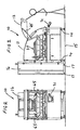
- Figure 1 shows the apparatus 10 without a housing whilst figures 2 and 3 show the apparatus 10 with a housing.
- the housing 11 has a door 12 shown in its open position in Figure 3.
- the door 12 shown in figure 3 is supported by struts 65 which serve to maintain the door in a raised position when the door is opened.
- the apparatus 10 has a frame 13 terminating in adjustable legs 14.
- the legs 14 normally rest upon ground 15 and allow the apparatus 10 to be levelled relative to the ground 15.
- An elevator housing 16 is located adjacent to the apparatus 10.
- the elevator housing 16 rests upon wheels 17.
- the housing 16 contains a bin 18 for tablets or other discrete articles. In figure 1 the bin 18 is shown twice; once in its lowered position and a second time in its raised position.
- the elevator housing of course contains only one bin 18.
- the housing 16 has a door (not shown) present on that side opposed to housing 11, The door may be opened and when the bin is in its lowered position tablets or other discrete articles may be deposited into the bin 18.
- Motor 19 is coupled to lead screws 20 arranged on opposite sides within the housing by drive members 21.
- the bin 18 is connected to the lead screws 20 by followers 22. Operation of the motor 19 causes the bin 18 to be driven between its two positions.
- tablets When the bin 18 is in its raised position tablets may be dispersed from the bin 18 over delivery chute 23 and onto the filling head 30.
- the apparatus 10 has a control console 31.
- the filling head 30 is mounted for rotation with the shaft 32 and the head 30 may be raised and lowered with respect to platform or table 33.
- the filling head 30 includes a plurality of circumferentially spaced metering stations described in greater detail below.
- the head has a container carousel 34 mounted to it such that when the head is rotated the carousel rotates with the head. Likewise, when the head is raised or lowered, the carousel 34 is also raised or lowered. By moving the carousel in the vertical direction the spacing between the carousel and the platform 33 may be varied to allow the apparatus 20 to accommodate containers of a variety of sizes.
- Motor 40 is coupled to a gearbox 41 and both are mounted to a support 42.
- the gearbox 41 is coupled to shaft 32 and functions to rotate the filling head 30 and the container carousel 34 coupled to the head by stays 44.
- An infeed carousel 50 is mounted to shaft 51.
- Shaft 51 is driven by drive member 52 which extends between the gearbox 41 and a coupling 53.
- infeed carousel 50 and container carousel 34 are driven in synchronism.
- head 30 and hence carousel 34 are moved vertically, carousel 50 is correspondingly moved vertically.
- Motor 60 is coupled to lead screws 61 which extend through support 42 and when the screws 61 (there are three in number but only two are visible in figure 1) are caused to rotate and the head and carousel 50 are moved in unison in the vertical direction.
- a drive member 62 extends between the lead screws 61.
- the shute 23 is mounted at the end of a support 63 which has its lower end connected to the support 42. When the support 42 is moved vertically the shute 23 is likewise moved in the vertical direction.
- a container conveyor 70 extends across the apparatus and serves to convey empty containers to the apparatus and convey filled containers from the apparatus.
- the shaft 32 is located within an outer sleeve 75 and slip rings 76 extend around the sleeve 75.
- Brushes 77 are mounted relative to the head 30 and allow electrical supply and control signals to be coupled to the head.
- Control circuitry may be located within housing 78 carried by the head and the apparatus is controlled by console 31.
- the space between the shaft 32 and the sleeve 75 may be supplied with compressed air which is made available to operate pneumatic operators associated with the metering stations.
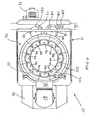
- Figure 4 is a plan view of the apparatus 10 of the invention.
- a container conveyor is shown extending across the apparatus 10.
- Empty containers 80 are presented by the conveyor 70 to the infeed carousel 50.
- Carousel 50 has a container receiving recesses 81 circumferentially spaced around its peripherary and empty containers 80 are picked up by the carousel 50 as the carousel rotates in an anti clockwise direction and presents those containers to the container carousel 34 (see figures 1 and 8) which rotates with the head 30.
- the head 30 rotates in a clockwise direction.
- the head has a plurality of metering stations 90 to 101 arranged circumferentially spaced around the head 30.
- An outwardly and upwardly flared skirt 110 extends around the head and ensures that tablets delivered by shute 23 are directed towards the metering stations.
- Two vacuum lines 111, 112 allow debris to be removed from the stations 90 to 101 in a manner described below.
- An outfeed carousel 120 receives filled containers 121 from the head 30 and presents them to the conveyor 70 so that they may be transported from the apparatus.
- Carousel 120 although not visible in figure 1 is mounted on a shaft like shaft 51 and is driven by gearbox 41 in a like manner to the way in which shaft 51 is driven.
- Carousel 120 is vertically movable in unison with the vertical movement of carousel 50 and is vertically movable in a similar way to which carousel 50 is vertically movable.
- Carousel 120 has container receiving recesses 121 circumferentially spaced around it for receiving containers. When the head is rotated in a clockwise fashion the carousels 50 and 120 both rotate in an anticlockwise direction .
- the apparatus 10 functions such that the conveyor 70 moves in a direction from the lower part of figure 4 to the upper part of the figure.
- the conveyor may be moved in the reverse direction and in which case carousels 120 and 50 would then be rotated in a clockwise direction and the container carousel 34 would be rotated in an anticlockwise direction.
- Empty containers would be introduced by the conveyor 70 from the upper part of the figure as viewed in figure 4 and filled containers would be available on the conveyor 70 at the lower part of the figure as viewed in figure 4.
- FIGS 5a and 5b show details of a sorting wheel 130.
- a sorting wheel 130 Such a wheel is present in each metering station and is mounted for rotation in the station.
- the wheel 130 has an outer periphery with a plurality of circumferentially spaced tablet receiving passages 131.
- Each passage 131 functions to pick up a single tablet as the wheel rotates.
- the passages 131 are defined by spaced webs 132 which extend slightly beyond the periphery of the wheel to define a tablet delivery opening 133 between the webs 132 and slightly beyond the periphery of the wheel.
- the wheel 130 has a central aperture 134 for receiving a drive shaft which terminates in a locking extension extending across the shaft.
- the diametrically extending slots 135 are adapted to receive the locking extension. One of these slots is shallow and the owner extends completely through the wheel.
- Figure 5b shows a diametrical sectional view across the sorting wheel 130.
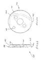
- Figures 6a and 6b show views of a backing plate 140.
- the backing plates are located within the metering stations and are fixed against rotation.
- a sorting wheel like that described in relation to figures 5a and 5b is located above each backing plate and in use rotates relative to the plate.
- the plate 140 has a delivery port 141 which extends from one face of the plate to the other face.
- a registry opening 142 extends through the plate and receives a registry pin 150 (see figure 7) which extends outwardly from a face of each metering station.
- Plate 140 has a flat portion 143 at one location on its periphery. This portion 143 provides a degree of clearance between the plate 140 and face 151 of the metering station to allow for vacuum extraction of debris from the metering station. A debris extraction passage extends across a rear face of plate 140.
- Figure 7 is a view into a metering station with the wheel 130 and plate 140 removed.
- the station has a delivery passage 152 at one side thereof.
- a tablet may be presented to port 141 of plate 140 and may then pass in a controlled manner through passage 152.
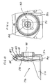
- Figure 8 is a view similar to the view shown in figure 4 but with some parts of the apparatus removed to show further details.
- Figure 8 shows the carousels 50 and 120 with their respective container receiving recesses 81 and 121.
- Container carousel 34 has container receiving recesses 160 which, with the rotation directions shown in the figure, receive empty containers 80 from carousel 50, convey the containers towards carousel 121 whilst the containers are being filled and present filled containers 161 to carousel 120.
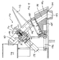
- Figure 9 shows detail of a metering station 170.
- the sorting wheel and plate of figures 5 and 6 have been omitted from this view.
- Part of the skirt 110 which extends around the metering stations is visible in this view.
- Spring biased locking shaft 171 extends outwardly from the station.
- Handle 172 may be grasped to allow the shaft 171 to be partially withdrawn from the station against the action of the spring 173.
- the shaft 171 may be rotated through 90° to rotate locking bar 174 to allow one of the slots 135 in the wheel (see fig 5) to align with the bar 174 to allow the wheel to be removed.
- One of the slots extends right through the wheel whilst the other is relatively shallow like shown in figure 5b.
- Bar 174 locates in the shallow slot 135 to lock the wheel 130 in position in the station 170 after plate 140 (in figure 6) has been positioned with pin 150 being received in aperture 142.
- Motor 175 is able to rotate shaft 171 and hence rotates the wheel 130 normally received in the metering station. Tablets dispensed by the wheel progress through port 141 (see figure 6), through passage 152, through a counting head 180 and through passage 181 in mounting block 182 and out through outlet opening 183 and into a container to be filled normally located below outlet 183.
- the counting head 180 carries optical sensors which detect and count the number of tablets passing from passage 152 and to passage 181.
- Block 182 has a recess 184 which receives a gate 185.
- the gate is movable by a pneumatically driven cylinder assembly 186 from the open position shown, to a closed position once a desired tablet count has been received from the head 180 to prevent further tablets from exiting through the outlet. Once the desired count has been obtained the motor 175 is controlled to stop rotation of the wheel 130.
- Figures 10 and 11 show metering station 170 with the wheel 130 and plate 140 in position.
- the wheel 130 has a shallow locking slot 190 for receiving locking bar 174 (see figure 9) and a through slot 191 through which the bar 174 may pass to allow the wheel 130 to be removed from the station.
- the plate 140 has a stepped portions 192 provide cavities 193.
- the flat portion 143 (see figure 6a) on the plate 140 provides clearance 194 between the plate and an adjacent part of stations.
- Debris extraction passage 144 extends from the upper cavity 193 to the lower cavity 193.
- Port 195 allows a source of vacuum to be coupled to the station and any debris which may collect in the station may be removed from the station by vacuum and the debris may be withdrawn from the spaces provided by the clearance and the cavity 193.
Landscapes
- Engineering & Computer Science (AREA)
- Mechanical Engineering (AREA)
- Basic Packing Technique (AREA)
- Supplying Of Containers To The Packaging Station (AREA)
- Specific Conveyance Elements (AREA)
- Container Filling Or Packaging Operations (AREA)
Claims (19)
- Vorrichtung (10) zum Befüllen von Behältern mit einzelnen Gegenständen, wobei die Vorrichtung (10) ein Behälterfördersystem (70) zum Transportieren von zu füllenden Behältern (80) zu der Vorrichtung (10) und zum Transportieren gefüllter Behälter (121) aus der Vorrichtung (10), einen drehbaren Füllkopf (30) und ein Behälterkarussell (34) mit einer Vielzahl von Behälter aufnehmenden Zonen aufweist, die zur Drehung mit dem Kopf (30) angebracht sind, wobei eine Vielzahl von Behältern von dem Kopf (30) gefüllt werden, während das Karussell (34) die Behälter synchron mit dem Kopf (30) bewegt, und gefüllte Behälter werden dem Fördersystem (70) von dem Karussell (34) übergeben und aus dem Füllkopf (30) wegbefördert, dadurch gekennzeichnet, dass der drehbare Füllkopf (30) benachbart zu dem Behälterfördersystem (70) positioniert ist, wobei der Füllkopf (30) eine Vielzahl von umlaufend beabstandeten Dosierstationen (90 bis 101; 170) jeweils zum Dosieren und Abgeben eines Stroms einer vorab festgelegten Anzahl von einzelnen Gegenständen in einen Behälter aufweist.
- Vorrichtung nach Anspruch 1, die eine Plattform (33) beinhaltet, auf der die Behälter ruhen können, während sie befüllt werden, wobei der Kopf (30) und das Karussell (34) in Richtung der Plattform (33) und von dieser weg bewegbar sind.
- Vorrichtung nach Anspruch 2, die ein Zuführkarussell (50) zum Aufnehmen von Behältern aus dem Fördersystem (70) und zum Übergeben der Behälter dem Behälterkarussell (34) beinhaltet.
- Vorrichtung nach Anspruch 3, die ein Wegführkarussell (120) zum Aufnehmen von Behältern aus dem Behälterkarussell (34) und zum Übergeben der Behälter dem Behälterfördersystem (70) beinhaltet.
- Vorrichtung nach Anspruch 4, worin das Zuführ- (50) und das Wegführkarussell (120) zusammen mit dem Kopf (30) und dem Behälterkarussell (34) in Richtung der Plattform (33) und von dieser weg bewegbar sind.
- Vorrichtung nach Anspruch 5, die einen Antrieb (32, 40, 41, 44) zum Drehen des Kopfes (30) und der Karusselle (34, 50, 120) beinhaltet.
- Vorrichtung nach Anspruch 5, die einen Antrieb zum Bewegen des Kopfes (30) und der Karusselle (34, 50, 120) beinhaltet.
- Vorrichtung nach Anspruch 1, die eine sich um den Kopf (30) erstreckende Blende (110) zum Lenken der Gegenstände in Richtung der Dosierstationen (90 bis 101; 170) beinhaltet.
- Vorrichtung nach Anspruch 1, worin jede Dosierstation (90 bis 101; 170) einen Zuführkanal (152) für Gegenstände, eine Stützplatte (140) mit einer Abgabeöffnung (141), die sich dort hindurch erstreckt und mit dem Zuführkanal (142) verbunden ist sowie ein Sortierrad (130) beinhaltet, das gegen die Platte (140) positioniert ist und zur Drehung relativ zu der Platte (140) angebracht ist, um die Gegenstände zu der Abgabeöffnung (141) zu bringen, während sich das Rad dreht.
- Vorrichtung nach Anspruch 9, worin die Dosierstation (90 bis 101; 170) einen Zählblock (180) mit einem Sensor für Gegenstände zum Zählen der Anzahl von Gegenständen, die durch die Abgabeöffnung (141) der Platte (140) hindurchgehen, beinhaltet.
- Vorrichtung nach Anspruch 10, worin jede Dosierstation einen steuerbaren Schieber (185) beinhaltet, der von dem Sensor betreibbar ist, um den Fluss von Gegenständen aus der Station anzuhalten, sobald eine vorab festgelegte Zählung erreicht worden ist.
- Vorrichtung nach Anspruch 10, worin die Drehung des Sortierrads (130) angehalten wird, sobald eine vorab festgelegte Zählung von Gegenständen erreicht worden ist.
- Vorrichtung nach Anspruch 11, worin der Schieber (185) durch einen Aktuator (186) zwischen einer offenen Position, die Gegenständen ermöglicht. aus dem Zuführkanal (152) zu fließen, und einer geschlossenen Position, die den Fluss von Gegenständen aus dem Zuführkanal (152) verhindert, gleitend bewegbar ist.
- Vorrichtung nach Anspruch 9, worin jedes Sortierrad (130) eine Vielzahl von umlaufend beabstandeten, Gegenstände aufnehmenden Durchgängen (131) aufweist, die von beabstandeten Stegen (132) festgelegt sind.
- Vorrichtung nach Anspruch 14, worin sich die Stege (132) über einen Rand des Rads (132) hinaus und über den Rand des Rads (130) hinaus erstrecken.
- Vorrichtung nach Anspruch 9, worin die Stützplatte (140) einen gestuften oberen und unteren Teil an einem Rand davon und einen flachen, Zwischenraum bereitstellenden Teil (143) an einer diametral entgegengesetzten Stelle auf dem Rand aufweist, und ein Ablagerungsextraktionsdurchgang (144) erstreckt sich zwischen dem oberen (193) und unteren (194) gestuften Teil.
- Vorrichtung nach Anspruch 16, worin die Abgabeöffnung (141) zwischen dem gestuften oberen Teil (193) und dem flachen, Zwischenraum bereitstellenden Teil (143) sowie zu einer Seite der Platte (140) positioniert ist.
- Vorrichtung nach Anspruch 1, die einen Elevator (16) für Gegenstände benachbart zu dem Füllkopf (30) zum Zuführen von Gegenständen zu den Dosierstationen beinhaltet
- Vorrichtung nach Anspruch 18, worin der Elevator (16) ein Behältnis (18) für Gegenstände zur Bewegung zwischen einer abgesenkten Behältnisfüllposition und einer erhöhten Position, bei der Gegenstände in dem Behältnis (18) den Dosierstationen (90 bis 101; 170) zugeführt werden können, beinhaltet.
Applications Claiming Priority (2)
| Application Number | Priority Date | Filing Date | Title |
|---|---|---|---|
| AUPP656498 | 1998-10-19 | ||
| AUPP6564A AUPP656498A0 (en) | 1998-10-19 | 1998-10-19 | An apparatus for filling containers with discrete articles |
Publications (2)
| Publication Number | Publication Date |
|---|---|
| EP0995678A1 EP0995678A1 (de) | 2000-04-26 |
| EP0995678B1 true EP0995678B1 (de) | 2005-06-01 |
Family
ID=3810785
Family Applications (1)
| Application Number | Title | Priority Date | Filing Date |
|---|---|---|---|
| EP99308178A Expired - Lifetime EP0995678B1 (de) | 1998-10-19 | 1999-10-18 | Vorrichtung zum Befüllen von Behältern mit einzelnen Gegenständen |
Country Status (6)
| Country | Link |
|---|---|
| US (1) | US6421982B1 (de) |
| EP (1) | EP0995678B1 (de) |
| AT (1) | ATE296752T1 (de) |
| AU (1) | AUPP656498A0 (de) |
| CA (1) | CA2286928A1 (de) |
| DE (1) | DE69925558D1 (de) |
Families Citing this family (14)
| Publication number | Priority date | Publication date | Assignee | Title |
|---|---|---|---|---|
| WO2004000654A1 (en) * | 2002-06-24 | 2003-12-31 | Campbell Soup Company | Control systems and methods of dispensing items |
| US7063215B2 (en) * | 2002-06-24 | 2006-06-20 | Campbell Soup Company | Control systems and methods of dispensing items |
| US20040164088A1 (en) * | 2002-06-24 | 2004-08-26 | John Baranowski | Dispensing and diversion systems and methods |
| WO2004001350A1 (en) * | 2002-06-24 | 2003-12-31 | Campbell Soup Company | Dispenser and methods of dispensing items |
| AU2003277849A1 (en) | 2002-06-24 | 2004-01-06 | Campbell Soup Company | Dispensing and diversion system and method |
| US7152756B2 (en) * | 2002-06-24 | 2006-12-26 | Campbell Soup Company | Dispensing systems and methods |
| WO2004000655A1 (en) * | 2002-06-24 | 2003-12-31 | Campbell Soup Company | Dispensing system and method |
| US7128204B2 (en) * | 2002-06-24 | 2006-10-31 | Campbell Soup Company | Dispensers and methods of dispensing items |
| TWI313062B (en) * | 2002-09-13 | 2009-08-01 | Ind Tech Res Inst | Method for producing active plastic panel displayers |
| ITBO20030034A1 (it) * | 2003-01-24 | 2004-07-25 | Mg 2 Srl | Unita' per l'alimentazione di capsule in una macchina per il riempimento di capsule. |
| US8607828B2 (en) * | 2007-09-20 | 2013-12-17 | Catalent Cts (Kansas City), Llc | Apparatus and method for filling containers |
| US8745961B2 (en) * | 2008-08-22 | 2014-06-10 | Tension International, Inc. | Container dispersion and filling system |
| JP2010082052A (ja) * | 2008-09-30 | 2010-04-15 | Sanyo Electric Co Ltd | 薬剤供給装置 |
| CN114789827B (zh) * | 2022-04-22 | 2023-12-15 | 江苏独角兽电子科技有限公司 | 一种儿科小剂量药片灌装设备 |
Family Cites Families (8)
| Publication number | Priority date | Publication date | Assignee | Title |
|---|---|---|---|---|
| CH630306A5 (de) * | 1978-07-21 | 1982-06-15 | Sig Schweiz Industrieges | Einrichtung zum einfuellen von plaettchenfoermigen stuecken in behaelter. |
| DE2944494A1 (de) * | 1979-11-03 | 1981-05-14 | Fa. Rich. Hengstenberg, 7300 Esslingen | Einrichtung zum dosierten beschicken von behaeltnissen, insbesondere konservenglaesern, mit gewuerzen |
| DE4118878A1 (de) * | 1991-06-09 | 1993-01-14 | Norbert Kraemer | Verfahren zum entsorgen und weiterverarbeiten von aus einer tabletten- oder pillenpressmaschine kommenden tabletten oder pillen o.ae. und vorrichtung hierzu |
| US5713180A (en) * | 1991-09-24 | 1998-02-03 | H. G. Kalish, Inc. | System for transporting containers for use with an apparatus to process containers such as a tablet filling monoblock |
| US5522512A (en) * | 1994-05-09 | 1996-06-04 | Merck & Co., Inc. | System and method for automatically feeding, inspecting and diverting tablets for continuous filling of tablet containers |
| US5463839A (en) * | 1994-08-04 | 1995-11-07 | The Lakso Company | Apparatus for packaging a predetermined quantity of objects and a counting device therefor |
| US5762116A (en) | 1997-04-23 | 1998-06-09 | Moore; Leslie A. | System for filling bottles with pills |
| US6185901B1 (en) * | 1998-05-20 | 2001-02-13 | Aylward Enterprises, Inc. | Positive count rotary slat packaging apparatus and related methods |
-
1998
- 1998-10-19 AU AUPP6564A patent/AUPP656498A0/en not_active Abandoned
-
1999
- 1999-10-18 US US09/419,495 patent/US6421982B1/en not_active Expired - Lifetime
- 1999-10-18 EP EP99308178A patent/EP0995678B1/de not_active Expired - Lifetime
- 1999-10-18 DE DE69925558T patent/DE69925558D1/de not_active Expired - Lifetime
- 1999-10-18 AT AT99308178T patent/ATE296752T1/de not_active IP Right Cessation
- 1999-10-19 CA CA002286928A patent/CA2286928A1/en not_active Abandoned
Also Published As
| Publication number | Publication date |
|---|---|
| ATE296752T1 (de) | 2005-06-15 |
| US6421982B1 (en) | 2002-07-23 |
| DE69925558D1 (de) | 2005-07-07 |
| EP0995678A1 (de) | 2000-04-26 |
| CA2286928A1 (en) | 2000-04-19 |
| AUPP656498A0 (en) | 1998-11-05 |
Similar Documents
| Publication | Publication Date | Title |
|---|---|---|
| US6421982B1 (en) | Apparatus for filling in containers with discrete articles | |
| CA2099913C (en) | Machine for automatically positioning and aligning containers, such as plastic bottles | |
| US6681550B1 (en) | Apparatus and methods for filling containers with pills | |
| US6363687B1 (en) | Secured cell, rapid fill automated tablet order filling system | |
| US7258222B2 (en) | Article positioning machine | |
| EP2769776B1 (de) | Sortiervorrichtung mit kippbarem Trägerelement | |
| US3662872A (en) | Apparatus for orienting and feeding articles | |
| US6345487B1 (en) | High quality control tablet filler device | |
| JPH08217223A (ja) | 容器の姿勢を整えて整列状態で供給するための自動装置 | |
| US20040004085A1 (en) | System and method for dispensing prescriptions | |
| US20010045081A1 (en) | Positive count rotary slat packaging apparatus and related methods | |
| US5853077A (en) | Article handling device, combination and methods | |
| US20110113730A1 (en) | Packaging apparatus for handling pills and associated method | |
| US11565894B2 (en) | Rotary discharge of containers from a depalletizer | |
| US7036679B2 (en) | Dispensing and diversion systems and methods | |
| US8051971B2 (en) | Apparatus and method for positioning articles, comprising multiple unloading operations per cycle | |
| US6439367B1 (en) | Bowl diverter | |
| US5494399A (en) | Can end distributor apparatus | |
| US20040164088A1 (en) | Dispensing and diversion systems and methods | |
| JPH0652187B2 (ja) | 食品計量装置 | |
| CA1130250A (en) | Automatic confection packaging machine | |
| KR100556009B1 (ko) | 분배 공급 장치 및 분배 공급 방법 | |
| JPH11513648A (ja) | 缶蓋の供給装置 | |
| GB2341374A (en) | Article handling apparatus | |
| JPS63272629A (ja) | 錠剤の搬送充填装置 |
Legal Events
| Date | Code | Title | Description |
|---|---|---|---|
| PUAI | Public reference made under article 153(3) epc to a published international application that has entered the european phase |
Free format text: ORIGINAL CODE: 0009012 |
|
| AK | Designated contracting states |
Kind code of ref document: A1 Designated state(s): AT BE CH CY DE DK ES FI FR GB GR IE IT LI LU MC NL PT SE |
|
| AX | Request for extension of the european patent |
Free format text: AL;LT;LV;MK;RO;SI |
|
| 17P | Request for examination filed |
Effective date: 20001018 |
|
| AKX | Designation fees paid |
Free format text: AT BE CH CY DE DK ES FI FR GB GR IE IT LI LU MC NL PT SE |
|
| 17Q | First examination report despatched |
Effective date: 20040628 |
|
| GRAP | Despatch of communication of intention to grant a patent |
Free format text: ORIGINAL CODE: EPIDOSNIGR1 |
|
| GRAS | Grant fee paid |
Free format text: ORIGINAL CODE: EPIDOSNIGR3 |
|
| GRAA | (expected) grant |
Free format text: ORIGINAL CODE: 0009210 |
|
| AK | Designated contracting states |
Kind code of ref document: B1 Designated state(s): AT BE CH CY DE DK ES FI FR GB GR IE IT LI LU MC NL PT SE |
|
| PG25 | Lapsed in a contracting state [announced via postgrant information from national office to epo] |
Ref country code: NL Free format text: LAPSE BECAUSE OF FAILURE TO SUBMIT A TRANSLATION OF THE DESCRIPTION OR TO PAY THE FEE WITHIN THE PRESCRIBED TIME-LIMIT Effective date: 20050601 Ref country code: LI Free format text: LAPSE BECAUSE OF FAILURE TO SUBMIT A TRANSLATION OF THE DESCRIPTION OR TO PAY THE FEE WITHIN THE PRESCRIBED TIME-LIMIT Effective date: 20050601 Ref country code: IT Free format text: LAPSE BECAUSE OF FAILURE TO SUBMIT A TRANSLATION OF THE DESCRIPTION OR TO PAY THE FEE WITHIN THE PRE;WARNING: LAPSES OF ITALIAN PATENTS WITH EFFECTIVE DATE BEFORE 2007 MAY HAVE OCCURRED AT ANY TIME BEFORE 2007. THE CORRECT EFFECTIVE DATE MAY BE DIFFERENT FROM THE ONE RECORDED.SCRIBED TIME-LIMIT Effective date: 20050601 Ref country code: FI Free format text: LAPSE BECAUSE OF FAILURE TO SUBMIT A TRANSLATION OF THE DESCRIPTION OR TO PAY THE FEE WITHIN THE PRESCRIBED TIME-LIMIT Effective date: 20050601 Ref country code: CH Free format text: LAPSE BECAUSE OF FAILURE TO SUBMIT A TRANSLATION OF THE DESCRIPTION OR TO PAY THE FEE WITHIN THE PRESCRIBED TIME-LIMIT Effective date: 20050601 Ref country code: BE Free format text: LAPSE BECAUSE OF FAILURE TO SUBMIT A TRANSLATION OF THE DESCRIPTION OR TO PAY THE FEE WITHIN THE PRESCRIBED TIME-LIMIT Effective date: 20050601 Ref country code: AT Free format text: LAPSE BECAUSE OF FAILURE TO SUBMIT A TRANSLATION OF THE DESCRIPTION OR TO PAY THE FEE WITHIN THE PRESCRIBED TIME-LIMIT Effective date: 20050601 |
|
| REG | Reference to a national code |
Ref country code: GB Ref legal event code: FG4D |
|
| REG | Reference to a national code |
Ref country code: CH Ref legal event code: EP |
|
| REG | Reference to a national code |
Ref country code: IE Ref legal event code: FG4D |
|
| REF | Corresponds to: |
Ref document number: 69925558 Country of ref document: DE Date of ref document: 20050707 Kind code of ref document: P |
|
| PG25 | Lapsed in a contracting state [announced via postgrant information from national office to epo] |
Ref country code: SE Free format text: LAPSE BECAUSE OF FAILURE TO SUBMIT A TRANSLATION OF THE DESCRIPTION OR TO PAY THE FEE WITHIN THE PRESCRIBED TIME-LIMIT Effective date: 20050901 Ref country code: GR Free format text: LAPSE BECAUSE OF FAILURE TO SUBMIT A TRANSLATION OF THE DESCRIPTION OR TO PAY THE FEE WITHIN THE PRESCRIBED TIME-LIMIT Effective date: 20050901 Ref country code: DK Free format text: LAPSE BECAUSE OF FAILURE TO SUBMIT A TRANSLATION OF THE DESCRIPTION OR TO PAY THE FEE WITHIN THE PRESCRIBED TIME-LIMIT Effective date: 20050901 |
|
| PG25 | Lapsed in a contracting state [announced via postgrant information from national office to epo] |
Ref country code: DE Free format text: LAPSE BECAUSE OF FAILURE TO SUBMIT A TRANSLATION OF THE DESCRIPTION OR TO PAY THE FEE WITHIN THE PRESCRIBED TIME-LIMIT Effective date: 20050902 |
|
| PG25 | Lapsed in a contracting state [announced via postgrant information from national office to epo] |
Ref country code: ES Free format text: LAPSE BECAUSE OF FAILURE TO SUBMIT A TRANSLATION OF THE DESCRIPTION OR TO PAY THE FEE WITHIN THE PRESCRIBED TIME-LIMIT Effective date: 20050912 |
|
| PG25 | Lapsed in a contracting state [announced via postgrant information from national office to epo] |
Ref country code: IE Free format text: LAPSE BECAUSE OF NON-PAYMENT OF DUE FEES Effective date: 20051018 Ref country code: GB Free format text: LAPSE BECAUSE OF NON-PAYMENT OF DUE FEES Effective date: 20051018 Ref country code: CY Free format text: LAPSE BECAUSE OF FAILURE TO SUBMIT A TRANSLATION OF THE DESCRIPTION OR TO PAY THE FEE WITHIN THE PRESCRIBED TIME-LIMIT Effective date: 20051018 |
|
| PG25 | Lapsed in a contracting state [announced via postgrant information from national office to epo] |
Ref country code: MC Free format text: LAPSE BECAUSE OF NON-PAYMENT OF DUE FEES Effective date: 20051031 Ref country code: LU Free format text: LAPSE BECAUSE OF NON-PAYMENT OF DUE FEES Effective date: 20051031 |
|
| PG25 | Lapsed in a contracting state [announced via postgrant information from national office to epo] |
Ref country code: PT Free format text: LAPSE BECAUSE OF FAILURE TO SUBMIT A TRANSLATION OF THE DESCRIPTION OR TO PAY THE FEE WITHIN THE PRESCRIBED TIME-LIMIT Effective date: 20051103 |
|
| NLV1 | Nl: lapsed or annulled due to failure to fulfill the requirements of art. 29p and 29m of the patents act | ||
| REG | Reference to a national code |
Ref country code: CH Ref legal event code: PL |
|
| PLBE | No opposition filed within time limit |
Free format text: ORIGINAL CODE: 0009261 |
|
| STAA | Information on the status of an ep patent application or granted ep patent |
Free format text: STATUS: NO OPPOSITION FILED WITHIN TIME LIMIT |
|
| 26N | No opposition filed |
Effective date: 20060302 |
|
| GBPC | Gb: european patent ceased through non-payment of renewal fee |
Effective date: 20051018 |
|
| EN | Fr: translation not filed | ||
| REG | Reference to a national code |
Ref country code: IE Ref legal event code: MM4A |
|
| PG25 | Lapsed in a contracting state [announced via postgrant information from national office to epo] |
Ref country code: FR Free format text: LAPSE BECAUSE OF NON-PAYMENT OF DUE FEES Effective date: 20051031 |
|
| PG25 | Lapsed in a contracting state [announced via postgrant information from national office to epo] |
Ref country code: FR Free format text: LAPSE BECAUSE OF NON-PAYMENT OF DUE FEES Effective date: 20050601 |