EP0997327A2 - Radaufhängung für Fahrzeug mit höhenregelbarer Ladeplattform - Google Patents
Radaufhängung für Fahrzeug mit höhenregelbarer Ladeplattform Download PDFInfo
- Publication number
- EP0997327A2 EP0997327A2 EP99125956A EP99125956A EP0997327A2 EP 0997327 A2 EP0997327 A2 EP 0997327A2 EP 99125956 A EP99125956 A EP 99125956A EP 99125956 A EP99125956 A EP 99125956A EP 0997327 A2 EP0997327 A2 EP 0997327A2
- Authority
- EP
- European Patent Office
- Prior art keywords
- chassis
- bracket
- trailing arm
- stub axle
- wheel mounting
- Prior art date
- Legal status (The legal status is an assumption and is not a legal conclusion. Google has not performed a legal analysis and makes no representation as to the accuracy of the status listed.)
- Ceased
Links
Images





Classifications
-
- B—PERFORMING OPERATIONS; TRANSPORTING
- B60—VEHICLES IN GENERAL
- B60G—VEHICLE SUSPENSION ARRANGEMENTS
- B60G5/00—Resilient suspensions for a set of tandem wheels or axles having interrelated movements
- B60G5/04—Resilient suspensions for a set of tandem wheels or axles having interrelated movements with two or more pivoted arms, the movements of which are resiliently interrelated, e.g. the arms being rigid
-
- B—PERFORMING OPERATIONS; TRANSPORTING
- B60—VEHICLES IN GENERAL
- B60G—VEHICLE SUSPENSION ARRANGEMENTS
- B60G11/00—Resilient suspensions characterised by arrangement, location or kind of springs
- B60G11/02—Resilient suspensions characterised by arrangement, location or kind of springs having leaf springs only
- B60G11/04—Resilient suspensions characterised by arrangement, location or kind of springs having leaf springs only arranged substantially parallel to the longitudinal axis of the vehicle
-
- B—PERFORMING OPERATIONS; TRANSPORTING
- B60—VEHICLES IN GENERAL
- B60G—VEHICLE SUSPENSION ARRANGEMENTS
- B60G17/00—Resilient suspensions having means for adjusting the spring or vibration-damper characteristics, for regulating the distance between a supporting surface and a sprung part of vehicle or for locking suspension during use to meet varying vehicular or surface conditions, e.g. due to speed or load
- B60G17/015—Resilient suspensions having means for adjusting the spring or vibration-damper characteristics, for regulating the distance between a supporting surface and a sprung part of vehicle or for locking suspension during use to meet varying vehicular or surface conditions, e.g. due to speed or load the regulating means comprising electric or electronic elements
- B60G17/017—Resilient suspensions having means for adjusting the spring or vibration-damper characteristics, for regulating the distance between a supporting surface and a sprung part of vehicle or for locking suspension during use to meet varying vehicular or surface conditions, e.g. due to speed or load the regulating means comprising electric or electronic elements characterised by their use when the vehicle is stationary, e.g. during loading, engine start-up or switch-off
-
- B—PERFORMING OPERATIONS; TRANSPORTING
- B60—VEHICLES IN GENERAL
- B60G—VEHICLE SUSPENSION ARRANGEMENTS
- B60G3/00—Resilient suspensions for a single wheel
- B60G3/02—Resilient suspensions for a single wheel with a single pivoted arm
- B60G3/12—Resilient suspensions for a single wheel with a single pivoted arm the arm being essentially parallel to the longitudinal axis of the vehicle
- B60G3/14—Resilient suspensions for a single wheel with a single pivoted arm the arm being essentially parallel to the longitudinal axis of the vehicle the arm being rigid
-
- B—PERFORMING OPERATIONS; TRANSPORTING
- B60—VEHICLES IN GENERAL
- B60P—VEHICLES ADAPTED FOR LOAD TRANSPORTATION OR TO TRANSPORT, TO CARRY, OR TO COMPRISE SPECIAL LOADS OR OBJECTS
- B60P1/00—Vehicles predominantly for transporting loads and modified to facilitate loading, consolidating the load, or unloading
- B60P1/02—Vehicles predominantly for transporting loads and modified to facilitate loading, consolidating the load, or unloading with parallel up-and-down movement of load supporting or containing element
- B60P1/025—Vehicles predominantly for transporting loads and modified to facilitate loading, consolidating the load, or unloading with parallel up-and-down movement of load supporting or containing element with a loading platform inside the wheels of a same axle and being lowerable below the axle
-
- B—PERFORMING OPERATIONS; TRANSPORTING
- B60—VEHICLES IN GENERAL
- B60P—VEHICLES ADAPTED FOR LOAD TRANSPORTATION OR TO TRANSPORT, TO CARRY, OR TO COMPRISE SPECIAL LOADS OR OBJECTS
- B60P1/00—Vehicles predominantly for transporting loads and modified to facilitate loading, consolidating the load, or unloading
- B60P1/64—Vehicles predominantly for transporting loads and modified to facilitate loading, consolidating the load, or unloading the load supporting or containing element being readily removable
-
- B—PERFORMING OPERATIONS; TRANSPORTING
- B60—VEHICLES IN GENERAL
- B60P—VEHICLES ADAPTED FOR LOAD TRANSPORTATION OR TO TRANSPORT, TO CARRY, OR TO COMPRISE SPECIAL LOADS OR OBJECTS
- B60P3/00—Vehicles adapted to transport, to carry or to comprise special loads or objects
- B60P3/42—Vehicles adapted to transport, to carry or to comprise special loads or objects convertible from one use to a different one
-
- B—PERFORMING OPERATIONS; TRANSPORTING
- B60—VEHICLES IN GENERAL
- B60G—VEHICLE SUSPENSION ARRANGEMENTS
- B60G2200/00—Indexing codes relating to suspension types
- B60G2200/10—Independent suspensions
- B60G2200/13—Independent suspensions with longitudinal arms only
- B60G2200/132—Independent suspensions with longitudinal arms only with a single trailing arm
-
- B—PERFORMING OPERATIONS; TRANSPORTING
- B60—VEHICLES IN GENERAL
- B60G—VEHICLE SUSPENSION ARRANGEMENTS
- B60G2202/00—Indexing codes relating to the type of spring, damper or actuator
- B60G2202/10—Type of spring
- B60G2202/11—Leaf spring
- B60G2202/112—Leaf spring longitudinally arranged
-
- B—PERFORMING OPERATIONS; TRANSPORTING
- B60—VEHICLES IN GENERAL
- B60G—VEHICLE SUSPENSION ARRANGEMENTS
- B60G2204/00—Indexing codes related to suspensions per se or to auxiliary parts
- B60G2204/10—Mounting of suspension elements
- B60G2204/12—Mounting of springs or dampers
- B60G2204/121—Mounting of leaf springs
-
- B—PERFORMING OPERATIONS; TRANSPORTING
- B60—VEHICLES IN GENERAL
- B60G—VEHICLE SUSPENSION ARRANGEMENTS
- B60G2204/00—Indexing codes related to suspensions per se or to auxiliary parts
- B60G2204/40—Auxiliary suspension parts; Adjustment of suspensions
- B60G2204/422—Links for mounting suspension elements
-
- B—PERFORMING OPERATIONS; TRANSPORTING
- B60—VEHICLES IN GENERAL
- B60G—VEHICLE SUSPENSION ARRANGEMENTS
- B60G2204/00—Indexing codes related to suspensions per se or to auxiliary parts
- B60G2204/80—Interactive suspensions; arrangement affecting more than one suspension unit
- B60G2204/81—Interactive suspensions; arrangement affecting more than one suspension unit front and rear unit
-
- B—PERFORMING OPERATIONS; TRANSPORTING
- B60—VEHICLES IN GENERAL
- B60G—VEHICLE SUSPENSION ARRANGEMENTS
- B60G2204/00—Indexing codes related to suspensions per se or to auxiliary parts
- B60G2204/80—Interactive suspensions; arrangement affecting more than one suspension unit
- B60G2204/83—Type of interconnection
- B60G2204/8302—Mechanical
-
- B—PERFORMING OPERATIONS; TRANSPORTING
- B60—VEHICLES IN GENERAL
- B60G—VEHICLE SUSPENSION ARRANGEMENTS
- B60G2300/00—Indexing codes relating to the type of vehicle
- B60G2300/04—Trailers
-
- B—PERFORMING OPERATIONS; TRANSPORTING
- B60—VEHICLES IN GENERAL
- B60G—VEHICLE SUSPENSION ARRANGEMENTS
- B60G2300/00—Indexing codes relating to the type of vehicle
- B60G2300/38—Low or lowerable bed vehicles
Definitions
- the present invention relates to vehicles either non-powered, such as trailers, or powered, such as pick-up trucks, trucks and vans, having a vertically adjustable bed, and in particular to a suspension or wheel mounting system for such vehicles.
- Standard vehicles such as vans and trucks have been used for the transportation of cargo.
- loading, unloading and positioning of cargo can be difficult.
- Adjustable trays have been proposed as shown in Australian Patent 573414 and Australian Patent Application 70142/91.
- parallelogram linkages in the form of "dog leg” or “boomerang” linkages are used, with the power means or rams acting on the linkages normal to the displacement of the tray. Further in both of these specifications the tray swings to a position rearward of the back of the vehicle, which could present problems in use.
- US Patent 4,673,328 again a parallelogram-type linkage is used having four pivotable tracks.
- the parent application EP 95912969.3 (0699142) seeks to ameliorate the disadvantages of the prior art and provides a vehicle comprising a U-shaped chassis, a tray adapted to be supported between the arms of said U-shaped chassis and drive means to move said tray between a raised transport position and a ground engaging loading position such that said tray retains substantially the same orientation throughout its movement between said transport position and said loading position, and a wheel assembly located intermediate the ends of each arm of the chassis, characterised in that the chassis is formed by a top rail having two substantially parallel arm members and a base member linking said arm members, a bottom rail substantially overlaid by said top rail, and having two substantially parallel arm members and a base member linking said arm members, and a plurality of elongated hollow, substantially parallel members, rigidly joining said top and bottom rails; the tray having a plurality of posts parallel to each other extending from the tray; each of said posts mating in sliding engagement within a respective elongated hollow substantially parallel member, so as to enhance the rigidity of the chassis and to
- the present invention comprises a wheel assembly adapted for connection to a chassis of a vehicle having a first trailing arm pivotally suspended from a first end to the chassis; a first wheel mounting stub axle located at or adjacent to the free end of the first trailing arm; a first connection means located adjacent said first wheel mounting stub axle; characterised in that the assembly further comprises: a second trailing arm pivotally suspended, from a first end, to the chassis and angled with respect to the chassis in the direction as the first trailing arm; a second wheel mounting stub axle located at or adjacent the free end of the second trailing arm; a second connection means located adjacent said second wheel mounting stub axle; a first bracket located on the chassis intermediate the said first and second trailing arms; a second bracket located on the chassis on one side of the first bracket beyond said first wheel mounting stub axle; a third bracket located on the other side of said first bracket beyond said second wheel mounting stub axle; a pivoting linkage connected to said first bracket and extending on each side thereof, a
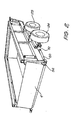
- a trailer is shown schematically in figures 1 and 2 embodying the present invention.
- the trailer 1 comprises a yoke or U-shaped chassis 2 and a drop tray 3.
- a tailgate 4 is located at the rear of the trailer 1; the tailgate 4 being hingedly connected to the side wall 6 or to the drop tray decking 5.
- the tailgate is unlatched and can be either swung to the side or dropped or lifted out, and then the drop tray 3 is lowered or dropped to the ground.
- the tailgate 4 is hingedly connected to the tray floor 5.
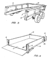
- the chassis 2 as shown in figures 1, 2 & 3 comprises two top rails 7 joined by a top end rail 3. Reinforcing struts 9 link the top rails 7 and 8 to identical bottom side rails 10 and bottom end rails 11 respectively.
- hollow tubes 12 which are adapted to mate telescopically with the upright post 13 of the tray 3.
- Suitable cladding (not shown) is placed on the outer surface forming a stable side wall.
- a drop tray 3 is constructed as shown in figures 4 & 9, having two side members 14 joined by traverse members (not shown), with a decking 5 secured across on top. Upright posts 13 extend normal to the plane of the drop tray decking 5. A sheet 16 is connected normal to the decking 5 a distance away from the posts 13.
- gussets 17 are connected across the last two traverse members 18 and the back plate 19.
- the side sheet 16 as shown in figure 4 has nylon strips 20 located thereon to act as a bearing strip against the hollow tube 12.
- any suitable lifting means could be used such as motor-driven thread and fixed nut arrangement, or cables.
- hydraulic cylinders 21 are connected to the side rail 7 and have their cylinder rod 22 passing through the bottom side rail 10 to engage with the side member 14 of the tray 2 at a connection 23.
- a hydraulic cylinder 21 is located adjacent the four corners of the frame.
- the cylinders are activated, simultaneously raising and lowering the tray 3 parallel to the plane of the - chassis.
- posts 13 and hollow tubes 12 be normal to the frame, as they could be at any suitable angle such as 45° to move the tray 2 rearwardly of the vehicle.
- male post could be on the chassis with the female hollow members on the tray.
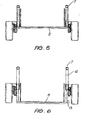
- This system utilises two wheels 24 and 25 on each side of the chassis 2.
- Each wheel 24 and 25 is connected to a stub axle 26 and 27 respectively, extending from the trailing arms 28 and 29 which are pivotally connected to a support rail 15 attached to the bottom rail 10.
- Extending opposite the stub axles 26 and 27 at the free ends of the trailing arms 28 and 29 are projections 30 and 31. These projections are pivotally secured by any suitable means such as U-bolts 32 backing plate 33 and nuts 34 to the respective leaf springs 35.
- a bracket 36 Located intermediate the trailing arms 28 and 29 is a bracket 36 connected to the support rail 15.
- a first linkage 37 is pivotally connected intermediate its ends to the bracket 36.
- a first end 38 is pivotally connected to one end of the leaf spring 35, while the other end of the leaf spring 35 is connected by a pivotal linkage 39 to the support rail 15.
- the second leaf spring 40 is pivotally connected at one end to the support rail 15 and connected at the other end by pivotal linkage 41 to the second end 42 of the first linkage 37.
- a support plate 43 is provided as particularly shown in figures 7 and 8.
- the trailing arms 28 and 29 are mounted on a respective projection 44 with a bush and spacer (not shown).
- the support plate 43 has located at one end tubular section 47 which fits over the free end of the projection 44, with the cut out 48 accommodating the trailing arm 28, as shown in figure 7.
- the edge 49 of the support plate 43 is welded to the reinforcing struts 9, thus securing the trailing arm 28 and transferring the load back to the chassis 2.
- a modified suspension system is shown in figure 16 wherein a detailed view of the suspension connection to the trailing arm is shown.
- the tailgate 4 is raised and lowered by the tailgate cylinder 50 which is connected to the tray 3 by a connection 51 and to the linkage 52 on the tail gate 4 as shown in figure 1.
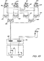
- FIG 10 is a schematic of the hydraulic system of one embodiment of the present invention.
- a hydraulic motor 53 draws fluid from the sump 54 and pumps it to a solenoid spool valve 55.
- the spool valve 55 passes fluid through to a first flow divider/combiner 56 such as that sold under the trade mark Hydraforin, which has two outlets dividing the flow to two further flow dividers/ combiners 57 and 58.
- the flow dividers/combiners are set to equally distribute the flow.
- each of the flow dividers/combiners 57 and 58 communicates with the power side or extension side of a respective tray operating cylinder 59, 60, 61 and 62, with the return side or retraction side of the cylinders being connected to respective inputs of flow divider/ combiners 63 to 64, the outputs of which are combined through a final flow divider/combiner 65 and back into the sump 54. In some circumstances it is not necessary to have flow dividers/combiners in the flow to the sump.
- the spool valve 55 has a second position wherein the flow is reversed through the flow dividers and the pistons are retracted.
- Pilot check valves 66, 67, 68 and 69 can be connected directly to the cylinders 59, 60, 61 and 62 as shown or a single pilot check valve (not shown) can be connected between the flow dividers 56 and 57 and the spool valve 55.
- an additional spool valve 70 is connected via the spool valve 55 to the hydraulic motor drive fluid, to open or close the tailgate depending on the position of the spool valve 70.
- FIG 11 Shown in figure 11 is the electrical schematic circuitry. As can be seen the trailer is self powered having its own battery 82. The circuitry provides a provision for direct charging of the trailer battery from the car to which it is connected.
- the floor-down solenoid 84, floor-up solenoid 85, tailgate-down solenoid 86, and tailgate-up solenoid 83 are connected via the respective floor-down relay 87, floor-up relay 88, tailgate-down relay 89 and tailgate-up relay 90 to the hydraulic valves 91 located next to the hydraulic motor 92.
- the wheels each have an electric brake 93 operated by the electric brake relay 94.
- Separate locking mechanisms are provided to lock the tray in its transport position. This can utilise any suitable arrangement coupled with a fail-safe system to prevent operation of the tray if the tray is still locked to the chassis.
- a pressure-sensitive valve whereby if an object is blocking the closing of the tailgate the increase in resistance to the movement of the ram is detected and the ram is disabled until the object is removed.
- the basic chassis construction can be used with many different body panel designs.
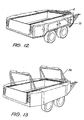
- One embodiment is shown in figure 12 in which storage units 71 are rigidly connected to the chassis 2 and the support plates 40, to provide additional rigidity of the chassis 2.
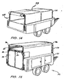
- the trailer 1 as shown in figure 12 can be modified to include a canopy 72 covering a framework 73 as shown in figure 14, or a carrying rack 74 as shown in figure 13.
- the basic trailer chassis can be modified to produce a horse float 75 as shown in figure 15.
- the operation of the tray is identical to the previously described operation, and the trailer chassis and wheel suspension systems are substantially identical to these described previously.
- the horse float body has a back entrance door 78 and a front door 79.
- the tray is divided into two stalls with appropriate horse padding on the divider and side walls 81.
- Each stall has its own rear door 80.
Landscapes
- Engineering & Computer Science (AREA)
- Mechanical Engineering (AREA)
- Transportation (AREA)
- Health & Medical Sciences (AREA)
- Public Health (AREA)
- Vehicle Body Suspensions (AREA)
- Body Structure For Vehicles (AREA)
- Fittings On The Vehicle Exterior For Carrying Loads, And Devices For Holding Or Mounting Articles (AREA)
- Handcart (AREA)
- Fluid-Pressure Circuits (AREA)
- Woven Fabrics (AREA)
Applications Claiming Priority (5)
| Application Number | Priority Date | Filing Date | Title |
|---|---|---|---|
| AUPM461994 | 1994-03-22 | ||
| AUPM4619A AUPM461994A0 (en) | 1994-03-22 | 1994-03-22 | Improved vehicle |
| AUPM7612A AUPM761294A0 (en) | 1994-08-24 | 1994-08-24 | Improved vehicle |
| AUPM761294 | 1994-08-24 | ||
| EP95912969A EP0699142B1 (de) | 1994-03-22 | 1995-03-22 | Fahrzeug mit höhenregelbarer ladeplattform |
Related Parent Applications (1)
| Application Number | Title | Priority Date | Filing Date |
|---|---|---|---|
| EP95912969A Division EP0699142B1 (de) | 1994-03-22 | 1995-03-22 | Fahrzeug mit höhenregelbarer ladeplattform |
Publications (2)
| Publication Number | Publication Date |
|---|---|
| EP0997327A2 true EP0997327A2 (de) | 2000-05-03 |
| EP0997327A3 EP0997327A3 (de) | 2000-07-26 |
Family
ID=25644647
Family Applications (2)
| Application Number | Title | Priority Date | Filing Date |
|---|---|---|---|
| EP95912969A Expired - Lifetime EP0699142B1 (de) | 1994-03-22 | 1995-03-22 | Fahrzeug mit höhenregelbarer ladeplattform |
| EP99125956A Ceased EP0997327A3 (de) | 1994-03-22 | 1995-03-22 | Radaufhängung für Fahrzeug mit höhenregelbarer Ladeplattform |
Family Applications Before (1)
| Application Number | Title | Priority Date | Filing Date |
|---|---|---|---|
| EP95912969A Expired - Lifetime EP0699142B1 (de) | 1994-03-22 | 1995-03-22 | Fahrzeug mit höhenregelbarer ladeplattform |
Country Status (13)
| Country | Link |
|---|---|
| US (2) | US5630693A (de) |
| EP (2) | EP0699142B1 (de) |
| JP (1) | JPH08511223A (de) |
| CN (1) | CN1128519A (de) |
| AT (1) | ATE197697T1 (de) |
| CA (1) | CA2145259A1 (de) |
| DE (1) | DE69519458T2 (de) |
| DK (1) | DK0699142T3 (de) |
| ES (1) | ES2155126T3 (de) |
| GR (1) | GR3035457T3 (de) |
| MX (1) | MXPA95001464A (de) |
| PT (1) | PT699142E (de) |
| WO (1) | WO1995026280A1 (de) |
Cited By (6)
| Publication number | Priority date | Publication date | Assignee | Title |
|---|---|---|---|---|
| US6986519B2 (en) | 1997-01-31 | 2006-01-17 | Aloha, Llc | Low profile chassis and suspension |
| US7108271B2 (en) | 1997-01-31 | 2006-09-19 | Earl Dallas Smith | Axleless vehicle suspension system |
| WO2008004935A1 (en) * | 2006-07-05 | 2008-01-10 | Volvo Lastvagnar Ab | Vehicle suspension levelling control |
| US7425005B2 (en) | 2003-10-24 | 2008-09-16 | Aloha, Llc | Suspensions for low floor vehicles |
| US7559400B2 (en) | 1997-01-31 | 2009-07-14 | Aloha, Llc | Low profile chassis and suspension |
| CN104670349A (zh) * | 2013-12-03 | 2015-06-03 | 湖北华舟重工应急装备股份有限公司 | 一种可自装卸货物的半挂车 |
Families Citing this family (61)
| Publication number | Priority date | Publication date | Assignee | Title |
|---|---|---|---|---|
| AUPN032694A0 (en) * | 1994-12-23 | 1995-01-27 | Thanksmate Pty Ltd | Improved vehicle |
| US5906419A (en) * | 1995-12-07 | 1999-05-25 | Tooling Technology Centre, Inc. | Wheel mounting assembly for installing a transmission-based anti-lock braking system sensor thereon |
| AUPO029696A0 (en) * | 1996-06-06 | 1996-07-04 | Dodcor Pty Ltd | Ground level access vehicle |
| WO1998028422A1 (en) | 1996-12-20 | 1998-07-02 | Human Genome Sciences, Inc. | Raidd, a novel cell death adaptor molecule |
| GB2324278A (en) * | 1997-02-20 | 1998-10-21 | J & A Promotions Ltd | Vehicle with vertically movable deck |
| AUPO707997A0 (en) | 1997-05-29 | 1997-06-19 | Workman Industries Pty Ltd | Vehicle cargo lift |
| GB9713033D0 (en) * | 1997-06-23 | 1997-08-27 | Lennox Albert G | Pallet platform for skip-lorry loading |
| AU745330B2 (en) * | 1997-09-16 | 2002-03-21 | Razorback Vehicles Corporation Pty. Ltd. | A raisable/lowerable vehicle bed carrying loads |
| AUPO924597A0 (en) | 1997-09-16 | 1997-10-09 | Razorback Vehicles Corporation Pty Ltd | A vehicle |
| WO1999015124A1 (en) | 1997-09-24 | 1999-04-01 | Workman Industries Pty. Ltd. | Vehicle with lift bed |
| US6123495A (en) * | 1998-06-16 | 2000-09-26 | Robertson Aviation L.L.C | Transport for moving and loading an auxiliary fuel tank |
| AUPQ478099A0 (en) * | 1999-12-21 | 2000-02-03 | Trailer Technologies Pty Ltd | Trailer |
| US6478321B1 (en) * | 2000-08-02 | 2002-11-12 | Mor/Ryde International, Inc. | Rubber shear spring assembly for tandem axle trailer |
| NL1018077C2 (nl) * | 2001-05-15 | 2002-11-19 | Knippenborg Assemblage V O F | Aanhanger. |
| US6648578B1 (en) * | 2002-03-28 | 2003-11-18 | Richard W. Rouse | Trailer and lift assembly for same |
| US20030206791A1 (en) * | 2002-05-01 | 2003-11-06 | Ronald Paul Wroblewski | Elevator delivery system for use in truck body or trailer |
| US20050058528A1 (en) * | 2002-05-01 | 2005-03-17 | Wroblewski Ronald Paul | Elevator delivery system for use in truck body or trailer |
| US7044704B1 (en) * | 2003-03-03 | 2006-05-16 | Roose Manufacturing Co. | Portable load lifting bed |
| CA2421446A1 (en) * | 2003-03-10 | 2004-09-10 | Dory Tuvim | Trailer with hoist for container and the like |
| FR2859421A1 (fr) * | 2003-09-09 | 2005-03-11 | Fabien Lucien Yves Escroignard | Remorque de transport a hauteur de chargement variable |
| US20050220591A1 (en) * | 2004-04-05 | 2005-10-06 | Doskocil David L | Level lift trailer with detachable cargo bed |
| US7210888B2 (en) * | 2004-11-30 | 2007-05-01 | Frank Bearden | Bale hauling system |
| US7322627B1 (en) * | 2006-03-24 | 2008-01-29 | Clinton Jay Nicholson | Vertically adjustable truck bed |
| US7736115B2 (en) * | 2007-04-06 | 2010-06-15 | Jorge Omar Lambert | Trailer apparatus |
| US8105007B2 (en) * | 2007-05-21 | 2012-01-31 | Dunkel Peter L | Vehicle transport ramp system |
| US20090289238A1 (en) * | 2007-08-21 | 2009-11-26 | Ronald Norris Olson | Horizontal universal frame lift system |
| AU2008346714B2 (en) * | 2008-01-04 | 2013-01-24 | Innovare Motion Pty Ltd | A trailer with lowerable and raisable trailer bed |
| CA2645438C (en) * | 2008-02-06 | 2016-03-29 | Simard Suspensions Inc. | Tandem suspension for a vehicle |
| US8182193B2 (en) * | 2008-10-28 | 2012-05-22 | Max-Atlas | Trailer for transporting freight containers and method of use |
| US20110268543A1 (en) * | 2008-12-02 | 2011-11-03 | James W. Welch | Container trailer |
| CA2714255A1 (en) | 2009-09-01 | 2011-03-01 | Timbren Industries Inc. | Suspension mechanism |
| CN102079453B (zh) * | 2009-11-27 | 2013-04-24 | 中冶长天国际工程有限责任公司 | 一种装卸料装置及支撑装置 |
| DE102011011877A1 (de) * | 2011-02-21 | 2012-08-23 | Primero Trailer Gmbh & Co. Kg | Großtiertransportanhänger, insbesondere Pferdeanhänger |
| US8308213B1 (en) * | 2012-03-06 | 2012-11-13 | Sharkey Marvin B | Trailer with adjustable interior size and adjustable track |
| US9260045B2 (en) * | 2012-06-05 | 2016-02-16 | Chapman/Leonard Studio Equipment, Inc. | Camera crane transport vehicle |
| FR2996519A1 (fr) * | 2012-10-04 | 2014-04-11 | R M Construction | Dispositif de remorque d'enlevement et de transport d'un ou de plusieurs conteneurs. |
| US8925934B2 (en) * | 2013-02-07 | 2015-01-06 | Anderson Mfg., Inc. | Torsion slide suspension |
| CN103470559B (zh) * | 2013-09-13 | 2016-03-23 | 三一汽车制造有限公司 | 一种混凝土搅拌运输车 |
| US10071780B1 (en) * | 2014-12-11 | 2018-09-11 | Eric S. Burka | Stabilized two-wheeled trailer |
| USD791666S1 (en) * | 2014-12-22 | 2017-07-11 | Bradley Denton | Lifting gate for truck |
| USD791029S1 (en) * | 2014-12-22 | 2017-07-04 | Bradley Denton | Extended lifting gate for truck |
| CN105082914A (zh) * | 2015-07-11 | 2015-11-25 | 合肥正浩机械科技有限公司 | 运输车副车传动组件 |
| CN106114379A (zh) * | 2016-07-26 | 2016-11-16 | 耿亮 | 一种运输车尾部防护攀爬装置 |
| CN110114226B (zh) * | 2016-08-09 | 2023-08-11 | 法赫德·阿拉杰希 | 用于提升以及运输货物的拖车 |
| US10464607B1 (en) * | 2016-09-23 | 2019-11-05 | Classic Truck Trailer, Llc | Truck bed trailer |
| AU2018201919B2 (en) * | 2017-03-16 | 2024-05-30 | King Group of Companies Pty Ltd | Easy loading trailer |
| USD938310S1 (en) * | 2017-07-13 | 2021-12-14 | Daryn Yoder | Set of hitch handle and wheel supports for a portable blind |
| ES1208539Y (es) * | 2018-02-22 | 2018-06-21 | Corrales Antonio Parramon | Remolque con plataforma descendente |
| DE102018210208A1 (de) * | 2018-06-22 | 2019-12-24 | Zf Friedrichshafen Ag | Schutzvorrichtung für ein Parkierfahrzeug und Parkierfahrzeug |
| CN109530597B (zh) * | 2018-12-17 | 2023-12-19 | 南京迪威尔高端制造股份有限公司 | 重型模具运输双u型小车及快速更换系统和方法 |
| US11167614B2 (en) * | 2019-02-19 | 2021-11-09 | Rassini Suspensiones, S.A. De C.V. | Progressive rate leaf spring for vehicle suspension system |
| NL2027032B1 (nl) * | 2019-12-20 | 2021-10-14 | Bcw | Aanhangwagen |
| CN111169362B (zh) * | 2020-02-26 | 2025-03-11 | 镇江市高等专科学校 | 纵梁式移送车辆结构 |
| USD1012778S1 (en) | 2021-07-31 | 2024-01-30 | Daryn Yoder | Portable blind |
| US12157408B1 (en) * | 2023-07-25 | 2024-12-03 | Richard Leslie Williamson | Trailer system and methods of use |
| CN117360357B (zh) * | 2023-12-07 | 2024-02-09 | 山西省长治经坊煤业有限公司 | 一种井下履带式煤矿车 |
| AU2024323231B1 (en) * | 2023-12-14 | 2025-04-17 | Richard Bernobich | Level lift cargo trailer |
| WO2025123092A1 (en) * | 2023-12-14 | 2025-06-19 | Richard Bernobich | Level lift cargo trailer |
| JP7686313B1 (ja) * | 2024-06-21 | 2025-06-02 | 株式会社トーイングネット | 車両の輸送用トレーラの荷台の側壁の拡縮機構 |
| CN119388942A (zh) * | 2025-01-03 | 2025-02-07 | 江苏天龙车辆部件有限公司 | 一种电动汽车的底盘 |
| CN119927944A (zh) * | 2025-03-07 | 2025-05-06 | 徐州朗智信息科技有限公司 | 一种防护型低速无人驾驶机器人 |
Family Cites Families (28)
| Publication number | Priority date | Publication date | Assignee | Title |
|---|---|---|---|---|
| US1893695A (en) * | 1930-03-14 | 1933-01-10 | Earl M Hicks | Equalizing chassis |
| US2151870A (en) | 1938-04-19 | 1939-03-28 | Philip H Raven | Trailer |
| US2361323A (en) * | 1943-07-26 | 1944-10-24 | Joseph P Seghers | Vehicle |
| US3024931A (en) | 1959-10-15 | 1962-03-13 | William E Grover | Cable operated dump body |
| US3378277A (en) * | 1966-01-11 | 1968-04-16 | Gen Motors Corp | Tandem axle suspension |
| US4033606A (en) * | 1975-08-06 | 1977-07-05 | Reyco Industries, Inc. | Vehicle tandem suspensions |
| US4003583A (en) * | 1975-08-18 | 1977-01-18 | Stanzel Ned L | Trailer having a vertically adjustable bed |
| US4061353A (en) * | 1976-01-20 | 1977-12-06 | Eugene A. LeBoeuf | Transport lock for lift bed trailer |
| US4058325A (en) * | 1976-05-03 | 1977-11-15 | Schramm Arthur G | Elevating trailer |
| US4155471A (en) * | 1976-09-07 | 1979-05-22 | Yancy John L | Trailer/container unit |
| GB2034644B (en) * | 1978-11-22 | 1982-08-11 | Fruehauf Crane Ltd | Suspension system for a vehicle |
| AU530776B2 (en) * | 1979-08-24 | 1983-07-28 | Goth, James | Vehicle axle mounting arrangement |
| JPS5699833A (en) * | 1979-12-29 | 1981-08-11 | Kinki Shatai Kogyo Kk | Dump body elevating device for truck |
| JPS5699883A (en) * | 1980-01-16 | 1981-08-11 | Mitsubishi Heavy Ind Ltd | Mud barge with mobile mud tank |
| IL66627A (en) * | 1982-08-23 | 1985-02-28 | Hechtometal Handassa Technith | Means for loading fowl into a transporting vehicle |
| US4502707A (en) * | 1983-06-06 | 1985-03-05 | Boler Investments, Inc. | Tandem axle suspension system |
| ZA859080B (en) * | 1984-11-29 | 1986-08-27 | Hynbrood Pty Ltd | Trolley carrier |
| AU573414B2 (en) * | 1984-11-29 | 1988-06-09 | Hynbrood Pty. Ltd. | Trolley carrier |
| US4673328A (en) * | 1985-06-10 | 1987-06-16 | Shiels J Michael | Lift/tilt-bed trailer |
| GB8611257D0 (en) | 1986-05-08 | 1986-06-18 | Chown P A C | Drop-floor trailer |
| DE3812924A1 (de) * | 1988-04-18 | 1989-10-26 | Man Nutzfahrzeuge Ag | Radfahrzeug mit zwei benachbarten, jeweils einzeln aufgehaengten starrachsen |
| GB8902446D0 (en) * | 1989-02-03 | 1989-03-22 | Foster Peter M | Trailing arm suspension systems |
| SE464233B (sv) * | 1989-06-29 | 1991-03-25 | Juha Kotilainen | Lyftanordning vid ett fordon |
| AU626032B2 (en) * | 1989-10-13 | 1992-07-23 | Nanlyn Pty. Ltd. | Retractable suspension |
| AU642956B2 (en) * | 1991-01-31 | 1993-11-04 | Hynbrood Pty Limited | A vehicle chassis |
| US5209518A (en) * | 1991-03-11 | 1993-05-11 | Detroit Steel Products Co., Inc. | Dual-stage tapered leaf spring for a trailer |
| US5288197A (en) | 1992-02-05 | 1994-02-22 | Harris Wendell N | Equipment trailer |
| US5395202A (en) * | 1992-07-06 | 1995-03-07 | Peters; Frank D. | Camper cabin supporting and lifting apparatus |
-
1995
- 1995-03-22 ES ES95912969T patent/ES2155126T3/es not_active Expired - Lifetime
- 1995-03-22 CA CA002145259A patent/CA2145259A1/en not_active Abandoned
- 1995-03-22 AT AT95912969T patent/ATE197697T1/de active
- 1995-03-22 CN CN95190406.XA patent/CN1128519A/zh active Pending
- 1995-03-22 DK DK95912969T patent/DK0699142T3/da active
- 1995-03-22 DE DE69519458T patent/DE69519458T2/de not_active Expired - Fee Related
- 1995-03-22 MX MXPA95001464A patent/MXPA95001464A/es not_active Application Discontinuation
- 1995-03-22 JP JP7524867A patent/JPH08511223A/ja active Pending
- 1995-03-22 US US08/408,617 patent/US5630693A/en not_active Expired - Lifetime
- 1995-03-22 PT PT95912969T patent/PT699142E/pt unknown
- 1995-03-22 EP EP95912969A patent/EP0699142B1/de not_active Expired - Lifetime
- 1995-03-22 WO PCT/AU1995/000162 patent/WO1995026280A1/en not_active Ceased
- 1995-03-22 EP EP99125956A patent/EP0997327A3/de not_active Ceased
-
1997
- 1997-02-10 US US08/799,060 patent/US5820149A/en not_active Expired - Fee Related
-
2001
- 2001-02-22 GR GR20010400291T patent/GR3035457T3/el not_active IP Right Cessation
Cited By (7)
| Publication number | Priority date | Publication date | Assignee | Title |
|---|---|---|---|---|
| US6986519B2 (en) | 1997-01-31 | 2006-01-17 | Aloha, Llc | Low profile chassis and suspension |
| US7108271B2 (en) | 1997-01-31 | 2006-09-19 | Earl Dallas Smith | Axleless vehicle suspension system |
| US7559400B2 (en) | 1997-01-31 | 2009-07-14 | Aloha, Llc | Low profile chassis and suspension |
| US7425005B2 (en) | 2003-10-24 | 2008-09-16 | Aloha, Llc | Suspensions for low floor vehicles |
| US7703781B2 (en) | 2003-10-24 | 2010-04-27 | Aloha, Llc | Suspensions for low floor vehicle |
| WO2008004935A1 (en) * | 2006-07-05 | 2008-01-10 | Volvo Lastvagnar Ab | Vehicle suspension levelling control |
| CN104670349A (zh) * | 2013-12-03 | 2015-06-03 | 湖北华舟重工应急装备股份有限公司 | 一种可自装卸货物的半挂车 |
Also Published As
| Publication number | Publication date |
|---|---|
| EP0699142A4 (de) | 1996-08-28 |
| CA2145259A1 (en) | 1995-09-23 |
| GR3035457T3 (en) | 2001-05-31 |
| PT699142E (pt) | 2001-05-31 |
| US5820149A (en) | 1998-10-13 |
| MXPA95001464A (es) | 2010-10-04 |
| DE69519458D1 (de) | 2000-12-28 |
| WO1995026280A1 (en) | 1995-10-05 |
| EP0699142A1 (de) | 1996-03-06 |
| ES2155126T3 (es) | 2001-05-01 |
| US5630693A (en) | 1997-05-20 |
| CN1128519A (zh) | 1996-08-07 |
| EP0699142B1 (de) | 2000-11-22 |
| DE69519458T2 (de) | 2001-06-21 |
| ATE197697T1 (de) | 2000-12-15 |
| JPH08511223A (ja) | 1996-11-26 |
| DK0699142T3 (da) | 2001-03-19 |
| EP0997327A3 (de) | 2000-07-26 |
Similar Documents
| Publication | Publication Date | Title |
|---|---|---|
| EP0699142B1 (de) | Fahrzeug mit höhenregelbarer ladeplattform | |
| US5035462A (en) | Utility vehicle chassis having a vertically adjustable bed | |
| US5288197A (en) | Equipment trailer | |
| US5810544A (en) | Ground level loading trailer | |
| US6234740B1 (en) | Vehicle cargo lift | |
| US6135700A (en) | Transport vehicle deck lowering mechanism | |
| US5192176A (en) | Sectional van trailer having detachable, interchangeable compartments capable of forming a continuous van body with accompanying system for forming shelf decks and partition walls within cargo holding sections | |
| US8070415B2 (en) | Method and apparatus for unloading containers | |
| US6045316A (en) | Fifth wheel rollback trailer | |
| AU704241B2 (en) | Vehicle with vertically adjustable loading bed | |
| US8070414B2 (en) | Cargo carrying vehicle and method of operation | |
| AU4014099A (en) | Vehicle with adjustable loading bed | |
| WO1990008088A1 (en) | Sectional van trailer having detachable, interchangeable compartments capable of forming a continuous van body with accompanying system for forming shelf decks and partition walls within cargo holding sections | |
| US7651312B2 (en) | Truck with tilting deck | |
| EP1023026A1 (de) | Fahrzeug mit hebeplattform | |
| WO1995032917A1 (en) | Load transport vehicles | |
| WO1996034778A1 (en) | A vehicle | |
| EP1121082A1 (de) | Fahrzeug mit in höhe verstellbarer fussbodem | |
| NZ522096A (en) | Truck deck tilting mechanism | |
| CA1315155C (en) | Rail vehicle for transporting road semi-trailers | |
| AU9330598A (en) | Vehicle with lift bed | |
| AU4888899A (en) | Vehicle with lifting floor | |
| CA2035313A1 (en) | Vehicle chassis | |
| WO2001045971A1 (en) | Trailer | |
| CA2832189A1 (en) | Trailer assembly |
Legal Events
| Date | Code | Title | Description |
|---|---|---|---|
| PUAI | Public reference made under article 153(3) epc to a published international application that has entered the european phase |
Free format text: ORIGINAL CODE: 0009012 |
|
| AC | Divisional application: reference to earlier application |
Ref document number: 699142 Country of ref document: EP |
|
| AK | Designated contracting states |
Kind code of ref document: A2 Designated state(s): AT BE CH DE DK ES FR GB GR IE IT LI LU MC NL PT SE |
|
| RIN1 | Information on inventor provided before grant (corrected) |
Inventor name: SOBINA, ROMAN |
|
| PUAL | Search report despatched |
Free format text: ORIGINAL CODE: 0009013 |
|
| AK | Designated contracting states |
Kind code of ref document: A3 Designated state(s): AT BE CH DE DK ES FR GB GR IE IT LI LU MC NL PT SE |
|
| AKX | Designation fees paid |
Free format text: AT BE CH DE DK ES FR GB GR IE IT LI LU MC NL PT SE |
|
| 17P | Request for examination filed |
Effective date: 20010425 |
|
| GRAG | Despatch of communication of intention to grant |
Free format text: ORIGINAL CODE: EPIDOS AGRA |
|
| 17Q | First examination report despatched |
Effective date: 20020430 |
|
| STAA | Information on the status of an ep patent application or granted ep patent |
Free format text: STATUS: THE APPLICATION HAS BEEN REFUSED |
|
| 18R | Application refused |
Effective date: 20021026 |