EP0997587A1 - Dispositif pour la connexion des rails - Google Patents
Dispositif pour la connexion des rails Download PDFInfo
- Publication number
- EP0997587A1 EP0997587A1 EP99810913A EP99810913A EP0997587A1 EP 0997587 A1 EP0997587 A1 EP 0997587A1 EP 99810913 A EP99810913 A EP 99810913A EP 99810913 A EP99810913 A EP 99810913A EP 0997587 A1 EP0997587 A1 EP 0997587A1
- Authority
- EP
- European Patent Office
- Prior art keywords
- connecting element
- element according
- mounting rails
- rail
- mounting
- Prior art date
- Legal status (The legal status is an assumption and is not a legal conclusion. Google has not performed a legal analysis and makes no representation as to the accuracy of the status listed.)
- Granted
Links
- 230000004323 axial length Effects 0.000 claims description 4
- 230000005611 electricity Effects 0.000 abstract 1
- XLYOFNOQVPJJNP-UHFFFAOYSA-N water Substances O XLYOFNOQVPJJNP-UHFFFAOYSA-N 0.000 abstract 1
- 210000003128 head Anatomy 0.000 description 4
- 210000001061 forehead Anatomy 0.000 description 2
- 238000003780 insertion Methods 0.000 description 2
- 230000037431 insertion Effects 0.000 description 2
- 238000000034 method Methods 0.000 description 2
- 239000000725 suspension Substances 0.000 description 2
- 229910001060 Gray iron Inorganic materials 0.000 description 1
- XAGFODPZIPBFFR-UHFFFAOYSA-N aluminium Chemical compound [Al] XAGFODPZIPBFFR-UHFFFAOYSA-N 0.000 description 1
- 229910052782 aluminium Inorganic materials 0.000 description 1
- 230000037237 body shape Effects 0.000 description 1
- 238000004519 manufacturing process Methods 0.000 description 1
- 230000003319 supportive effect Effects 0.000 description 1
Images


Classifications
-
- F—MECHANICAL ENGINEERING; LIGHTING; HEATING; WEAPONS; BLASTING
- F16—ENGINEERING ELEMENTS AND UNITS; GENERAL MEASURES FOR PRODUCING AND MAINTAINING EFFECTIVE FUNCTIONING OF MACHINES OR INSTALLATIONS; THERMAL INSULATION IN GENERAL
- F16B—DEVICES FOR FASTENING OR SECURING CONSTRUCTIONAL ELEMENTS OR MACHINE PARTS TOGETHER, e.g. NAILS, BOLTS, CIRCLIPS, CLAMPS, CLIPS OR WEDGES; JOINTS OR JOINTING
- F16B37/00—Nuts or like thread-engaging members
- F16B37/04—Devices for fastening nuts to surfaces, e.g. sheets, plates
- F16B37/041—Releasable devices
- F16B37/043—Releasable devices with snap action
-
- F—MECHANICAL ENGINEERING; LIGHTING; HEATING; WEAPONS; BLASTING
- F16—ENGINEERING ELEMENTS AND UNITS; GENERAL MEASURES FOR PRODUCING AND MAINTAINING EFFECTIVE FUNCTIONING OF MACHINES OR INSTALLATIONS; THERMAL INSULATION IN GENERAL
- F16B—DEVICES FOR FASTENING OR SECURING CONSTRUCTIONAL ELEMENTS OR MACHINE PARTS TOGETHER, e.g. NAILS, BOLTS, CIRCLIPS, CLAMPS, CLIPS OR WEDGES; JOINTS OR JOINTING
- F16B7/00—Connections of rods or tubes, e.g. of non-circular section, mutually, including resilient connections
- F16B7/18—Connections of rods or tubes, e.g. of non-circular section, mutually, including resilient connections using screw-thread elements
Definitions
- the invention relates to a connecting element for mounting rails, the side walls or rear wall with regular perforations arranged at regular intervals are provided.
- mounting rails are used in many cases have an essential C-shaped cross section.
- the C-shaped mounting rails have a rear wall and two protruding side walls.
- the sidewalls limit an insertion slot running in the longitudinal direction.
- the side walls and possibly also the back wall are at regular intervals with standardized perforations and provided the like, the connection or the implementation of threaded rods and other components can serve.
- Such a mounting rail is, for example known from EP-A-0 798 505, which hereby forms an integral part of the present Patent application is declared.
- the mounting rail described there has an approximately C-shaped cross section. Your perforated at regular intervals Side walls have profiles running in the longitudinal direction. The profiles form undercut projections inside the mounting rail.
- the connecting element for mounting rails has a block-like Body that runs essentially parallel to one another at its longitudinal ends End faces and two pins protruding symmetrically from each other from the end faces having.
- the pegs have a largest diameter which corresponds to the diameter of the Side wall perforations of the mounting rails correspond, and are with undercut Side surfaces.
- a hole is provided in the body, the central axis of which parallel to the end faces and roughly through that of the length and width bisectors the intersection of the body.
- each pin has a substantially circular Cross section on.
- the undercut side surfaces extend advantageously over an angular range that is greater than 180 ° and does not exceed 320 °. By doing the undercut section of the pegs over an angular range greater than 180 ° extends, there is a secure form fit in the standardized side wall perforations guaranteed.
- the limitation of the extent of the undercut side surface an angular range of less than 320 ° facilitates assembly and alignment of the assembled connecting element.
- each pin preferably has one axial length, which is about 1 mm to about 1.5 mm.
- the angle of inclination at which the undercut long sides of the pegs into the associated end face of the body of the connecting element opens with Advantage about 60 ° to about 75 °, so that even when the mounting rail is loaded transversely positive connection of the clipped pins with the side walls guaranteed is.
- the body of the Connecting element is substantially cylindrical.
- a manufacturing process for the connector for example, die-cast aluminum, gray cast iron or similar procedures are used.
- the cylindrical body has a flattened long side that in the area of the not undercut portion of the side surfaces of the pins and is preferably oriented perpendicular to the hole in the body.
- the hole is in the body of the connector provided with a standard thread.
- the mother can be omitted, who otherwise on the end opposite the head of the screw must be screwed on.
- FIG. 1 This in perspective in Fig. 1, in Fig. 2 in side view and in Fig. 3 in end view illustrated embodiment of a connecting element according to the invention each provided with the reference number 1 as a whole.
- It essentially has one cylindrical body 2 with mutually parallel end faces 3 and 4.
- Die axial length of the body is based on the distance between the side surfaces of a mounting rail Voted. From each end face 3, 4 protrudes a pin 5, the axial length I corresponds to at least the wall thickness of the rail increased by 0.5 mm and is preferably about 1 mm to about 1.5 mm.
- the pin 5 have a essentially circular cross-section and have an undercut Side surface 6, the angle ⁇ with the associated side surface 3, 4 of the body 2 includes that is about 60 ° to about 75 °.
- the undercut side surface 6 extends over an angular range w which is greater than 180 ° but less than 320 °.
- the body 2 is provided with a flat 8.
- the cones 5 have a largest diameter d, the diameter of standardized Corresponds to side wall perforations of mounting rails.
- the body 2 is one Drilled through hole 7, which is preferably perpendicular to the flattening 8 of the body 2nd is arranged.
- the arrangement of the hole is chosen such that its central axis in the runs essentially parallel to the end faces 3, 4.
- the bore is preferably 7 provided such that its central axis is that of the length and width bisectors of the body 2 formed intersection.
- the second embodiment of the shown in Fig. 4 in side view The connecting element according to the invention is designated overall by reference number 10 Mistake. Its structure corresponds essentially to that in FIGS. 1-3 illustrated first embodiment 1 of a connecting element. For this For the same parts are given the same reference numerals. The difference is that the bore 7 in the body 2 with a standardized internal thread is provided, which is indicated in Fig. 4 with the reference numeral 11.
- the body 2 of the connecting element 1, 10 has a substantially cylindrical shape. It is understood that the body's shape, for example of a cuboid.
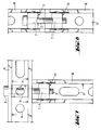
- FIG. 5 shows an assembly step of a connecting element, for example one 4, on a mounting rail M, the side walls are provided with perforations L.
- a connecting element for example one 4
- a mounting rail M Such mounting rails are for example in the EP-A-0 798 505, which hereby forms an integral part of the present Patent application is declared.
- the from the end faces of the body 2 of the Connecting element protruding pin 5 are by the side walls the mounting rail M limited opening slot introduced into the rail and in the The holes L are clipped onto the front end of the mounting rail M.
- the biggest Diameter d of the pin 5 corresponds to the diameter T of the Sidewall perforations L, so that the pin 5 simply slide into the perforations and these can enforce.
- a connection of two mounting rails M, N is shown, in which one of the Mounting rails N with their back against the front end of the first mounting rail M is arranged.
- the first mounting rail M is already with a connecting element 10 equipped, according to the process indicated in Fig. 5 in the last two Sidewall perforations in the area of the front end of the mounting rail M is clipped.
- the connecting element 10 is aligned such that its bore 7 with a Back wall hole R in the second mounting rail N is aligned.
- the two Mounting rails M, N are connected to each other by a screw S, which by the Rear wall perforation R of the second mounting rail N inserted and into the one Internal thread 11 provided bore 7 of the connecting element 10 is screwed.
- the head of the screw is supported on the rear wall of the second mounting rail N from.
- a suitable washer can Reduction of the passage opening can be used.
- Fig. 7 shows a variant of a connection of two mounting rails M, N, in which the second mounting rail N with a side wall at the front end of the first mounting rail M is arranged, which is already equipped with a connecting element 10.
- Both mounting rails M, N face the viewer with the opening slots.
- the rear wall perforations in both mounting rails M, N are each with the reference symbol R.
- the bore of the connecting element is aligned such that with the opposite side wall perforations of the second mounting rail N is aligned.
- the two mounting rails M, N are fixed using a Screw S through the side wall perforations of the second mounting rail N inserted and into the hole of the one installed in the first mounting rail M.
- Connection element 10 is screwed.
- the screw could only passed through the side wall perforation of one of the side walls of the second mounting rail his.
- the screw through the opposing holes in both To guide sidewalls.
- can in the second mounting rail N is a cuboid mounting block B with perpendicular to its side surfaces extending through holes H may be provided, which prevents the second Mounting rail N is pressed together when tightening screw S.
- FIG. 8 shows a situation in which two mounting rails M, N are connected to one another are that border with each other with their foreheads.
- Both mounting rails M, N are in the Area of their front ends equipped with connecting elements 1, 10, each in the last pair of side wall perforations are clipped.
- it is the connecting element 1 in the first mounting rail M by an embodiment with unthreaded through hole according to FIGS. 1-3, while the connecting element 10 in the second mounting rail N in the exemplary embodiment from FIG. 4 corresponds and has a bore provided with an internal thread.
- the holes of the two connecting elements 1, 10 are aligned with one another.
- connection variants indicated in FIGS. 6-8 serve only for illustration. It it goes without saying that the connecting element according to the invention also includes others Connection types allows the relative position of the mounting rails to each other can vary.
Landscapes
- Engineering & Computer Science (AREA)
- General Engineering & Computer Science (AREA)
- Mechanical Engineering (AREA)
- Mutual Connection Of Rods And Tubes (AREA)
- Mounting Components In General For Electric Apparatus (AREA)
- Flanged Joints, Insulating Joints, And Other Joints (AREA)
- Installation Of Indoor Wiring (AREA)
Applications Claiming Priority (2)
| Application Number | Priority Date | Filing Date | Title |
|---|---|---|---|
| DE19849201A DE19849201A1 (de) | 1998-10-26 | 1998-10-26 | Verbindungselement für Montageschienen |
| DE19849201 | 1998-10-26 |
Publications (2)
| Publication Number | Publication Date |
|---|---|
| EP0997587A1 true EP0997587A1 (fr) | 2000-05-03 |
| EP0997587B1 EP0997587B1 (fr) | 2003-02-26 |
Family
ID=7885601
Family Applications (1)
| Application Number | Title | Priority Date | Filing Date |
|---|---|---|---|
| EP99810913A Expired - Lifetime EP0997587B1 (fr) | 1998-10-26 | 1999-10-07 | Dispositif pour la connexion des rails |
Country Status (3)
| Country | Link |
|---|---|
| EP (1) | EP0997587B1 (fr) |
| AT (1) | ATE233353T1 (fr) |
| DE (2) | DE19849201A1 (fr) |
Cited By (1)
| Publication number | Priority date | Publication date | Assignee | Title |
|---|---|---|---|---|
| US10107323B2 (en) * | 2008-05-16 | 2018-10-23 | Marty Williams | Barrel nut assembly |
Families Citing this family (2)
| Publication number | Priority date | Publication date | Assignee | Title |
|---|---|---|---|---|
| DE102008055686A1 (de) * | 2008-10-27 | 2010-06-10 | Adolf Würth GmbH & Co. KG | Montageschiene |
| DE102017118912A1 (de) | 2017-08-18 | 2019-02-21 | Maximilian Rüttiger | Bausatz zur Halterung von Elementen an einem Gegenstand |
Citations (5)
| Publication number | Priority date | Publication date | Assignee | Title |
|---|---|---|---|---|
| GB1566914A (en) * | 1976-03-05 | 1980-05-08 | Itw Fastex Italia Spa | Fixing members of box section |
| CH660061A5 (en) * | 1982-07-01 | 1987-03-13 | Rudolf Huber Krattiger | Device for the butt connection of a profiled tube to a structural part running at right angles thereto |
| US5144780A (en) * | 1991-03-25 | 1992-09-08 | Gieling Thomas G | Portable structure |
| WO1997025541A1 (fr) * | 1996-01-12 | 1997-07-17 | Mita (Uk) Ltd. | Ameliorations concernant des dispositifs de fixation |
| EP0798505A1 (fr) * | 1996-03-28 | 1997-10-01 | HILTI Aktiengesellschaft | Rail de montage |
-
1998
- 1998-10-26 DE DE19849201A patent/DE19849201A1/de not_active Withdrawn
-
1999
- 1999-10-07 AT AT99810913T patent/ATE233353T1/de active
- 1999-10-07 EP EP99810913A patent/EP0997587B1/fr not_active Expired - Lifetime
- 1999-10-07 DE DE59904366T patent/DE59904366D1/de not_active Expired - Lifetime
Patent Citations (5)
| Publication number | Priority date | Publication date | Assignee | Title |
|---|---|---|---|---|
| GB1566914A (en) * | 1976-03-05 | 1980-05-08 | Itw Fastex Italia Spa | Fixing members of box section |
| CH660061A5 (en) * | 1982-07-01 | 1987-03-13 | Rudolf Huber Krattiger | Device for the butt connection of a profiled tube to a structural part running at right angles thereto |
| US5144780A (en) * | 1991-03-25 | 1992-09-08 | Gieling Thomas G | Portable structure |
| WO1997025541A1 (fr) * | 1996-01-12 | 1997-07-17 | Mita (Uk) Ltd. | Ameliorations concernant des dispositifs de fixation |
| EP0798505A1 (fr) * | 1996-03-28 | 1997-10-01 | HILTI Aktiengesellschaft | Rail de montage |
Cited By (1)
| Publication number | Priority date | Publication date | Assignee | Title |
|---|---|---|---|---|
| US10107323B2 (en) * | 2008-05-16 | 2018-10-23 | Marty Williams | Barrel nut assembly |
Also Published As
| Publication number | Publication date |
|---|---|
| DE19849201A1 (de) | 2000-04-27 |
| DE59904366D1 (de) | 2003-04-03 |
| ATE233353T1 (de) | 2003-03-15 |
| EP0997587B1 (fr) | 2003-02-26 |
Similar Documents
| Publication | Publication Date | Title |
|---|---|---|
| EP0641939B1 (fr) | Dispositif de fixation | |
| DE60022647T2 (de) | Implantat für osteosynthesevorrichtung, insbesondere für die wirbelsäule | |
| DE4034546A1 (de) | Halteelement aus kunststoff | |
| EP4357627A2 (fr) | Dispositif de compensation de tolérance | |
| DE4306877A1 (de) | Profilstabsystem für Rahmenkonstruktionen, Fahrzeugaufbauten, Regalsysteme, Werkstatt- und Laboreinrichtungen oder dergleichen | |
| DE8518780U1 (de) | Verbindungselement für Rohre | |
| DE69013713T2 (de) | Reklametafel-Bausatz. | |
| EP0997587B1 (fr) | Dispositif pour la connexion des rails | |
| DE202004018212U1 (de) | Montage- und Demontagevorrichtung für das Kugelgelenk eines Kraftfahrzeuges | |
| EP1396645A1 (fr) | Dispositif d'assemblage sous un angle de rails de montage | |
| DE2916003A1 (de) | Befestigungsvorrichtung, insbesondere fuer die verbindung von zwei bauteilen von bauwerken | |
| DE8906283U1 (de) | Verbindungsbeschlag für Stabelemente | |
| DE3514765C2 (fr) | ||
| DE9306773U1 (de) | Befestigungsvorrichtung aus Kunststoff, insbesondere für Platinen | |
| EP0959536B1 (fr) | Bloc multiprises | |
| EP1039154B1 (fr) | Système de fixation | |
| EP0267200A1 (fr) | Dispositif pour l'assemblage demontable de deux elements de construction. | |
| DE9012607U1 (de) | Klemmelement für eine Klemmvorrichtung | |
| DE20115618U1 (de) | Parallelverbinder | |
| EP4080069A1 (fr) | Système de fixation | |
| EP3406916B1 (fr) | Équerre pour profilés de support | |
| DE20016876U1 (de) | Tragwerk mit Knotenverbindern | |
| DE29603402U1 (de) | Rahmenwerk mit Winkel- oder Eckverbindungen von Metallprofilen, insbesondere aus Leichtmetall | |
| DE2943625C2 (de) | Rohrschelle | |
| EP1596076A1 (fr) | Dispositiv de fixation d'au moins deux pièces, utilisation et un procede de ce dispositiv |
Legal Events
| Date | Code | Title | Description |
|---|---|---|---|
| PUAI | Public reference made under article 153(3) epc to a published international application that has entered the european phase |
Free format text: ORIGINAL CODE: 0009012 |
|
| AK | Designated contracting states |
Kind code of ref document: A1 Designated state(s): AT CH DE FR GB LI |
|
| AX | Request for extension of the european patent |
Free format text: AL;LT;LV;MK;RO;SI |
|
| 17P | Request for examination filed |
Effective date: 20001103 |
|
| AKX | Designation fees paid |
Free format text: AT CH DE FR GB LI |
|
| 17Q | First examination report despatched |
Effective date: 20010926 |
|
| GRAG | Despatch of communication of intention to grant |
Free format text: ORIGINAL CODE: EPIDOS AGRA |
|
| GRAG | Despatch of communication of intention to grant |
Free format text: ORIGINAL CODE: EPIDOS AGRA |
|
| GRAH | Despatch of communication of intention to grant a patent |
Free format text: ORIGINAL CODE: EPIDOS IGRA |
|
| GRAH | Despatch of communication of intention to grant a patent |
Free format text: ORIGINAL CODE: EPIDOS IGRA |
|
| GRAA | (expected) grant |
Free format text: ORIGINAL CODE: 0009210 |
|
| AK | Designated contracting states |
Designated state(s): AT CH DE FR GB LI |
|
| REG | Reference to a national code |
Ref country code: GB Ref legal event code: FG4D Free format text: NOT ENGLISH |
|
| REG | Reference to a national code |
Ref country code: CH Ref legal event code: EP |
|
| REF | Corresponds to: |
Ref document number: 59904366 Country of ref document: DE Date of ref document: 20030403 Kind code of ref document: P |
|
| GBT | Gb: translation of ep patent filed (gb section 77(6)(a)/1977) | ||
| ET | Fr: translation filed | ||
| PLBE | No opposition filed within time limit |
Free format text: ORIGINAL CODE: 0009261 |
|
| STAA | Information on the status of an ep patent application or granted ep patent |
Free format text: STATUS: NO OPPOSITION FILED WITHIN TIME LIMIT |
|
| 26N | No opposition filed |
Effective date: 20031127 |
|
| PGFP | Annual fee paid to national office [announced via postgrant information from national office to epo] |
Ref country code: AT Payment date: 20101014 Year of fee payment: 12 |
|
| PGFP | Annual fee paid to national office [announced via postgrant information from national office to epo] |
Ref country code: DE Payment date: 20100908 Year of fee payment: 12 |
|
| PGFP | Annual fee paid to national office [announced via postgrant information from national office to epo] |
Ref country code: GB Payment date: 20101006 Year of fee payment: 12 |
|
| PGFP | Annual fee paid to national office [announced via postgrant information from national office to epo] |
Ref country code: CH Payment date: 20111012 Year of fee payment: 13 Ref country code: FR Payment date: 20111103 Year of fee payment: 13 |
|
| REG | Reference to a national code |
Ref country code: CH Ref legal event code: PL |
|
| REG | Reference to a national code |
Ref country code: AT Ref legal event code: MM01 Ref document number: 233353 Country of ref document: AT Kind code of ref document: T Effective date: 20121007 |
|
| GBPC | Gb: european patent ceased through non-payment of renewal fee |
Effective date: 20121007 |
|
| REG | Reference to a national code |
Ref country code: FR Ref legal event code: ST Effective date: 20130628 |
|
| PG25 | Lapsed in a contracting state [announced via postgrant information from national office to epo] |
Ref country code: DE Free format text: LAPSE BECAUSE OF NON-PAYMENT OF DUE FEES Effective date: 20130501 Ref country code: GB Free format text: LAPSE BECAUSE OF NON-PAYMENT OF DUE FEES Effective date: 20121007 Ref country code: LI Free format text: LAPSE BECAUSE OF NON-PAYMENT OF DUE FEES Effective date: 20121031 Ref country code: AT Free format text: LAPSE BECAUSE OF NON-PAYMENT OF DUE FEES Effective date: 20121007 Ref country code: CH Free format text: LAPSE BECAUSE OF NON-PAYMENT OF DUE FEES Effective date: 20121031 |
|
| REG | Reference to a national code |
Ref country code: DE Ref legal event code: R119 Ref document number: 59904366 Country of ref document: DE Effective date: 20130501 |
|
| PG25 | Lapsed in a contracting state [announced via postgrant information from national office to epo] |
Ref country code: FR Free format text: LAPSE BECAUSE OF NON-PAYMENT OF DUE FEES Effective date: 20121031 |