EP0997669B1 - Schalthebelvorrichtung für Automatikgetriebe mit Handschaltmodus - Google Patents
Schalthebelvorrichtung für Automatikgetriebe mit Handschaltmodus Download PDFInfo
- Publication number
- EP0997669B1 EP0997669B1 EP99121496A EP99121496A EP0997669B1 EP 0997669 B1 EP0997669 B1 EP 0997669B1 EP 99121496 A EP99121496 A EP 99121496A EP 99121496 A EP99121496 A EP 99121496A EP 0997669 B1 EP0997669 B1 EP 0997669B1
- Authority
- EP
- European Patent Office
- Prior art keywords
- shift lever
- groove
- lever
- shift
- mode
- Prior art date
- Legal status (The legal status is an assumption and is not a legal conclusion. Google has not performed a legal analysis and makes no representation as to the accuracy of the status listed.)
- Expired - Lifetime
Links
Images


Classifications
-
- F—MECHANICAL ENGINEERING; LIGHTING; HEATING; WEAPONS; BLASTING
- F16—ENGINEERING ELEMENTS AND UNITS; GENERAL MEASURES FOR PRODUCING AND MAINTAINING EFFECTIVE FUNCTIONING OF MACHINES OR INSTALLATIONS; THERMAL INSULATION IN GENERAL
- F16H—GEARING
- F16H59/00—Control inputs to control units of change-speed- or reversing-gearings for conveying rotary motion
- F16H59/02—Selector apparatus
- F16H59/0204—Selector apparatus for automatic transmissions with means for range selection and manual shifting, e.g. range selector with tiptronic
-
- F—MECHANICAL ENGINEERING; LIGHTING; HEATING; WEAPONS; BLASTING
- F16—ENGINEERING ELEMENTS AND UNITS; GENERAL MEASURES FOR PRODUCING AND MAINTAINING EFFECTIVE FUNCTIONING OF MACHINES OR INSTALLATIONS; THERMAL INSULATION IN GENERAL
- F16H—GEARING
- F16H59/00—Control inputs to control units of change-speed- or reversing-gearings for conveying rotary motion
- F16H59/02—Selector apparatus
- F16H2059/0239—Up- and down-shift or range or mode selection by repeated movement
-
- F—MECHANICAL ENGINEERING; LIGHTING; HEATING; WEAPONS; BLASTING
- F16—ENGINEERING ELEMENTS AND UNITS; GENERAL MEASURES FOR PRODUCING AND MAINTAINING EFFECTIVE FUNCTIONING OF MACHINES OR INSTALLATIONS; THERMAL INSULATION IN GENERAL
- F16H—GEARING
- F16H59/00—Control inputs to control units of change-speed- or reversing-gearings for conveying rotary motion
- F16H59/02—Selector apparatus
- F16H59/08—Range selector apparatus
- F16H59/10—Range selector apparatus comprising levers
-
- Y—GENERAL TAGGING OF NEW TECHNOLOGICAL DEVELOPMENTS; GENERAL TAGGING OF CROSS-SECTIONAL TECHNOLOGIES SPANNING OVER SEVERAL SECTIONS OF THE IPC; TECHNICAL SUBJECTS COVERED BY FORMER USPC CROSS-REFERENCE ART COLLECTIONS [XRACs] AND DIGESTS
- Y10—TECHNICAL SUBJECTS COVERED BY FORMER USPC
- Y10T—TECHNICAL SUBJECTS COVERED BY FORMER US CLASSIFICATION
- Y10T74/00—Machine element or mechanism
- Y10T74/20—Control lever and linkage systems
- Y10T74/20012—Multiple controlled elements
- Y10T74/20018—Transmission control
- Y10T74/20067—Control convertible between automatic and manual operation
Definitions
- the present invention relates to a shift lever apparatus of a transmission for a vehicle according to the preamble of claim 1.
- Such a shift lever apparatus is disclosed in US 5,205,180. Said document describes a shift lever apparatus of a transmission.
- the transmission has an automatic transmission mode and a manual transmission mode.
- the shift lever apparatus comprises a shift lever and a supporting shaft. Said supporting shaft supports an end of said shift lever so that said shaft lever is swingable in a right and left direction and a front and rear direction of the vehicle.
- a typical shift lever apparatus of such an automatic transmission is provided with an automatic transmission mode (A/T mode) and a manual transmission mode (M/T mode).
- the A/T mode includes parking gear (P), reverse gear (R), neutral gear (N), drive gear (D), second gear (2) and first gear (1) positions
- the M/T mode includes an upshift range (plus range) and a downshift range (minus range).
- a shift lever of such a shift lever apparatus is arranged to be swingable in a shift groove including an A/T mode shift groove, a M/T mode shift groove parallel with the A/T mode shift groove, and a lateral movement groove connecting the A/T mode shift groove and the M/T mode shift groove.
- Some kinds of transmissions are arranged to fix the gear position in the D position by laterally swinging the shift lever set at the D position through the lateral movement shift groove to the M/T mode shift groove. Further, by swinging the shift lever in the M/T mode shift groove along the front and rear direction, an upshift or a downshift is executed according to a frontward swing to a plus range or a rearward swing to a minus range.
- Such a transmission has been arranged to execute the change of the transmission mode only by means of a mode selector switch.
- Other types of transmissions have been arranged to execute the change of the transmission mode by moving a cable link lever from the D position to other position such as a second gear position, in addition to the operation of the mode selector switch.
- the transmission mode is changed by swinging the shift lever from the D position to the second gear position along the front and rear direction of the vehicle and by laterally swinging the shift lever from the second gear position to the M/T mode shift groove. Therefore, if this conventional transmission is employed, it is necessary to execute two steps operations for achieving the change of the transmission mode from the A/T mode to the M/T mode.
- a shift lever apparatus is for an automatic transmission having an automatic transmission mode and a manual transmission mode.
- the shift lever apparatus comprises a shift lever whose end is supported to a supporting shaft extending along a direction of a right and left direction of a vehicle.
- the supporting shaft is rotatable on its centre axis so that the shift lever is swingable in the right and left direction and a front and rear direction of the vehicle.
- a cable link lever is connected to the transmission and is swingably supported to the supporting shaft.
- the cable link lever is linked with the shift lever such that the cable link lever is swung on the centre axis of the supporting shaft according to the right and left directional swing of the shift lever.
- the shift lever apparatus is for an automatic transmission employed in an automotive vehicle.
- the shift lever apparatus is arranged to change a transmission mode from an automatic transmission mode (A/T mode) to a manual transmission mode (M/T mode) by tilting (swinging) a shift lever 11 set at a D (drive gear) position of an A/T mode shift groove 21 to a M/T mode shift groove 22.
- the shift lever apparatus comprises the shift elver 11 movable in a shift groove 20.
- the shift groove 20 comprises an A/T mode shift groove 21, a M/T mode shift groove 22 and a lateral shift groove 23 connecting A/T mode shift groove 21 and the M/T mode shift groove 22.
- the A/T mode shift groove 21 extends along a front and rear direction of the vehicle.
- the M/T mode shift groove 22 also extends along the front and rear direction of the vehicle so as to be parallel with the main groove 21a.
- the lateral groove 23 connects a rear end portion of the A/T mode shift groove 21 and an intermediate portion of the M/T mode shift groove 22.
- the combination of the A/T mode shift groove 21 and the lateral groove 23 generally forms L-shaped groove. Marks P, R, N and D, indicative of parking gear position, reverse gear position, neutral gear position and drive gear position, respectively, are marked on a right side portion of a shift groove defining plate 20a as shown in Fig. 1.
- a plus range mark (+) 7 is marked in the vicinity of a front end of the M/T mode shift groove 22, and a minus range mark (-) 8 is marked in the vicinity of a rear end of the M/T mode shift groove 22.
- a shift knob 2 having a push button 4 is connected to a top end portion of the shift lever 11.
- a lower end portion of the shift lever 11 is fixed to a bracket 12 of a channel shape.
- the bracket 12 is swingably connected through a shaft pin 14 to a rotatable shaft 13 extending in a right and left direction of the vehicle.
- the rotatable shaft 13 is rotatablly supported to a support (not show) so that the shaft 13 is rotatable on a centre axis of the shaft 13. Therefore, the shift lever 11 is set so as to be swingable in the front and rear direction and in the right and left direction of the vehicle.
- a branch lever 16 is installed to the shift lever 11 near the bracket 12 so as to be perpendicular to the shift lever 11 and parallel with the shaft 13.
- a cable link lever 15 is swingably installed to the shaft 13.
- a connecting groove 19 is formed at an upper end portion of the cable link lever 15.
- the other end portion of the cable link lever 15 is connected to the transmission through a shift cable (not show).
- the branch lever 16 extending from the shift lever 11 is arranged to be connected to and disconnected from the connecting groove 19 of the cable link lever 15 according to the lateral swing angle of the shift lever 11.
- the connecting groove 19 of the cable link lever 15 is constituted by an inclined groove 17 inclined from an upright state in the frontward direction of the vehicle and a straight groove 18 connected to a lower end of the inclined groove 17 and extending downward as shown in Fig. 3.
- the shift lever 11 and the cable link lever 15 are integrally swung in the front and rear direction of the vehicle.
- the shift lever 11 is swingable in the front and rear direction of the vehicle independently from the cable link lever 15.
- the change of the transmission mode is executed by laterally swinging the shift lever 11 in the D position of the A/T mode in the direction of the arrow M shown in Fig. 2.
- the branch lever 16 is put out from the straight groove 18 and pushes the cable link lever 15 in the direction of the arrow A shown in Fig. 3.
- This pushing in the direction of the arrow A rotates the cable link lever 15 on an axis of the shaft 13 in the direction of the arrow B (anticlockwise direction) in Fig. 3. Therefore, a shift cable (not shown) is pulled so as to execute a shifting operation to the second gear position as same as a conventional apparatus does by two step operation.
- the shift lever 11 When the transmission mode is changed from the M/T mode to the A/T mode, the shift lever 11 is set at a neutral position between the upshift position and the downshift position in the M/T mode shift groove 22 (the shift lever 11 is usually put at the neutral position, if the driver does not touch the shift lever 11 in the M/T mode shift groove 22), and the shift lever 11 is laterally moved through the lateral groove 23 from the M/T mode shift groove 22 to the A/T mode shift groove 21.
- the branch lever 16 slides along the inclined groove 19 while pushing a lower surface defining the inclined groove 19 in the direction of the arrow C in Fig. 3.
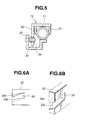
- FIG. 4 to 6 there is shown a second embodiment of the shift lever apparatus according to the present invention.
- the arrangement of a shift groove 20 and a shift lever 11 in the shift groove 20 is the same as that shown in Fig. 1 of the first embodiment. Therefore, the explanation of this arrangement shown in Fig. 1 will be omitted herein.
- a mechanism for swinging a cable link lever 15 in the front and rear direction of the vehicle according to the right and left directional swing of the shift lever 11 will be mainly discussed hereinafter.
- a lower end of the shift lever 11 is fixed to a bracket 12.
- the bracket 12 is swingably connected to a rotatable shaft 13 through a shaft pin 14. Therefore, the shift lever 11 is swingable in the A/T mode groove 21 along the front and rear direction of the vehicle and is swingable in the D position of the A/T mode groove 21 and the lateral groove 23 along the right and left direction of the vehicle.
- a cable link lever 15 is swingably supported to the shaft 13 in the vicinity of the shift lever 11.
- the cable link lever 15 comprises a channel shaped holding portion 31 which supports the shift lever 11 in the front and rear direction of the vehicle and a L-shaped plate portion 32 formed at an upper portion of the cable link lever 15. A bent end portion of the plate portion 32 is parallel to the shaft 13.
- a cam groove 33 is formed at the plate portion 32 as shown in Figs. 6A and 6B.
- the cam groove 33 has upper and lower inclined surfaces 33a and 33b, which are downwardly curved toward its opening and are inclined toward the front side of the vehicle from a horizontal state to an inclined state at which a front side is lower in height level than a rear side thereof. That is, the upper and lower inclined surfaces 33a and 33b are twisted as is clearly shown in Figs. 6A and 6B.
- a roller 34 is installed to the shift lever 11 through a bracket 35.
- the roller 34 is movably engaged with the cam groove 33 so that the roller 34 is slid on the inclined surfaces 33a and 33b of the cam groove 33 according to the lateral swing of the shift lever 11. More specifically, the roller 34 moves along the inclined surfaces 33a and 33b when the shift lever 11 is swung in the right and left direction of the vehicle, that is, when the change of the transmission mode is executed.
- This movement of the roller 34 in the cam groove 33 swings the cable link lever 15 by a twisted angle of the plate portion 32 according to the sliding amount of the roller 34 on the inclined surfaces 33a and 33b.
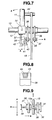
- a third embodiment of the shift lever apparatus there is shown a third embodiment of the shift lever apparatus according to the present invention.
- the arrangement of a shift groove 20 and a shift lever 11 in the shift groove 20 is the same as that shown in Fig. 1 of the first embodiment, and therefore the explanation thereof will be omitted herein.
- a mechanism for swinging a cable link lever 15 in the front and rear direction of the vehicle according to the right and left directional swing of the shift lever 11 will be mainly discussed hereinafter.
- a lower end of the shift lever 11 is fixed to a bracket 12.
- the bracket 12 is swingably connected to a rotatable shaft 13 through a shaft pin 14. Therefore, the shift lever 11 is swingable in the A/T mode groove 21 along the front and rear direction of the vehicle and is swingable in the lateral groove 23 along the right and left direction of the vehicle as same as the arrangements in the first and second embodiments.
- a cable link lever 15 is swingably supported to the shaft 13.
- Pair of levers 36 and 36 are installed to the shaft 13 so as to be swingable with the cable link lever 15 while being located both sides of the cable link lever 15, respectively.
- the levers 36 and 36 are loosely connected to the shaft 13 so as to be movable in the axial direction of the shaft 13.
- a fixing member 37 is installed at each lower end portion of each lever 36.
- a diagonal shaft 38 is inclinedly disposed between the pair of fixing members 37 and 37.
- the diagonal shaft 38 is connected to the fixing members 37 and 37 while penetrating a hole 15a of the cable connecting hole 15.
- the diagonal shaft 38 diagonally traverses the hole 15a on an imaginary horizontal surface including an axis of the diagonal shaft 38 while keeping its horizontal state.
- a plate 39 is installed at an opposite end of the fixing member 37 located between the shift lever 11 and the cable link lever 15.
- a lever 42 is installed at a lower portion of the bracket 12 and extends downwardly as shown in Fig. 7.
- a selector lever 41 having a pair of arms 40 and 40 is installed at a lower end of the lever 42. The arms 40 and 40 are arranged so as to sandwich the plate 39 therebetween.
- a generally channel-shaped recess 43 is formed at an upper end portion of the cable link lever 15.
- a branch lever 44 of a trapezoidal shape is integrally connected to the shift lever 11. The branch lever 44 extends from the shift lever 11 toward the recess 43 of the cable link lever 15, and its free end portion is received in the recess 43 of the cable link lever 15.
Landscapes
- Engineering & Computer Science (AREA)
- General Engineering & Computer Science (AREA)
- Mechanical Engineering (AREA)
- Arrangement Or Mounting Of Control Devices For Change-Speed Gearing (AREA)
- Mechanical Control Devices (AREA)
- Control Of Transmission Device (AREA)
Claims (12)
- Schalthebelvorrichtung eines Getriebes für eine Fahrzeug, wobei das Getriebe einen automatischen Getriebemodus und einen manuellen Getriebemodus hat, wobei die Schalthebelvorrichtung aufweist:dadurch gekennzeichnet, dass die Schalthebelvorrichtung außerdem aufweist:einen Schalthebel (11);eine Lagerwelle (13), die sich entlang einer Richtung einer rechten oder linken Richtung des Fahrzeuges erstreckt, wobei die Lagerwelle (13) rund um eine Mittelachse der Lagerwelle (13) drehbar ist, wobei die Lagerwelle (13) ein Ende des Schalthebels (11) lagert, so dass der Schalthebel (11) in einer rechten oder linken Richtung und einer vorderen und einer hinteren Richtung des Fahrzeuges schwenkbar ist,einen Kabelverbindungshebel (15), verbunden mit dem Getriebe und schwenkbar auf der Lagerwelle (13) gelagert; undeiner Einrichtung zum Schwenken des Kabelverbindungshebels (15) um die Mittelachse der Lagerwelle (13) entsprechend des rechts- oder linksgerichteten Schwenkens des Schalthebels (11).
- Schalthebelvorrichtung nach Anspruch 1, mit außerdem einer einstückigen Schwenkeinrichtung zum gemeinsamen Schwenken des Schalthebels (11) und des Kabelverbindungshebels (15) in der vorderen und hinteren Richtung des Fahrzeuges, wenn der Schalthebel (11) in den automatischen Getriebemodus festgestellt ist.
- Schalthebelvorrichtung nach Anspruch 1, wobei die Schwenkeinrichtung einen Abzweighebel (16), rechtwinklig mit dem Schalthebel (11) verbunden und eine Verbindungsnut (19), vorgesehen in dem Kabelverbindungshebel (15), enthält, wobei der Abzweighebel (16) mit der Verbindungsnut (19) im Eingriff ist, um den Kabelverbindungshebel (15) in einer vorderen und hinteren Richtung des Fahrzeuges zu schwenken, wenn der Schalthebel (11) in die rechte oder linke Richtung geschwenkt wird.
- Schalthebelvorrichtung nach Anspruch 3, wobei die Verbindungsnut (19) eine geneigte Nut (17) und eine gerade Nut (18) enthält, der Kabelverbindungshebel (15) um die Achse der Lagerwelle (13) geschwenkt wird, wenn der Abzweighebel (16) eine Oberfläche, die die geneigte Nut (17) bildet, entsprechend des rechts- oder linksgerichteten Schwingens des Schalthebels (11) drückt.
- Schalthebelvorrichtung nach Anspruch 1, wobei die Schwenkeinrichtung eine Walze (34), installiert in dem Schalthebel (11), und eine Nockennut (33), gebildet in einer Platte (32), enthält, die einstückig mit dem Kabelverbindungshebel (15) ist, wobei die Walze (34) in der Nockennut (33) gleitet, wenn der Schalthebel (11) entlang der rechten oder linken Richtung des Fahrzeuges geschwenkt wird, wobei der Kabelverbindungshebel (15) entlang der vorderen oder hinteren Richtung des Fahrzeuges geschwenkt wird, wenn die Walze (34) in der Nockennut (33) gleitet.
- Schalthebelvorrichtung nach Anspruch 5, wobei die Nockennut (33), gebildet durch obere und untere verdrehte Oberflächen (33a, 33b) gebildet ist, die nach unten in eine Richtung einer Öffnung der Nockennut (33) gekrümmt und verdreht sind, so dass sie allmählich entsprechend der Annäherung an ein Öffnungsende der Nockennut (33) derart geneigt sind, dass eine Vorderseite der Nockennut (33) niedriger im Höhenniveau als die Rückseite der Nockennut (33) ist.
- Schalthebelvorrichtung nach Anspruch 1, wobei die Schwenkeinrichtung eine Bohrung (15a), gebildet an dem Kabelverbindungshebel (15) aufweist, und eine diagonale Welle (38) diagonal die Bohrung (15a) durchdringt, wobei die diagonale Welle (38) mit dem Schalthebel (11) verbunden ist, der Kabelverbindungshebel (15) in die vordere und hintere Richtung des Fahrzeuges geschwenkt wird, wenn die diagonale Welle (38) in der Bohrung (15a) des Kabelverbindungshebels (15) entlang der Achse der Lagerwelle (13) entsprechend des rechts- oder linksgerichteten Schwenkens des Schalthebels (11) bewegt wird.
- Schalthebelvorrichtung nach Anspruch 1, die außerdem eine Schaltnut (20) aufweist, die eine automatische Getriebemodusnut (A/T) (21), eine manuelle Getriebenmodusnut (M/T) (22), parallel mit der A/T- Modusnut (21), und eine seitliche Nut (23) enthält, die die A/T- Modusnut (21) und die M/T- Modusnut (22) verbindet, wobei sich die A/T- Modusnut (21) und die M/T- Modusnut (22) entlang einer vorderen und hinteren Richtung des Fahrzeuges erstrecken, während die seitliche Nut (23) sich in die rechte und linke Richtung des Fahrzeuges erstreckt.
- Schalthebelvorrichtung nach Anspruch 2, wobei die einstückige Schwenkeinrichtung einen Abzweighebel (44) enthält, der sich rechtwinklig von dem Schalthebel (11) erstreckt und eine Nut, vorgesehen in dem Kabelverbindungshebel (15), wobei der Abzweighebel (44) mit der der Nut derart im Eingriff ist, dass der Kabelverbindungshebel (15) mit dem Schalthebel (11) in die vordere und hintere Richtung des Fahrzeuges geschwenkt wird, wenn der Schalthebel (11) in den automatischen Getriebemodus gesetzt ist, und wenn der Schalthebel (11) in die vordere und hintere Richtung geschwenkt wird.
- Schalthebelvorrichtung nach Anspruch 1, wobei die einstückige Schwenkeinrichtung einen kanalförmigen Verbindungsabschnitt des Kabelverbindungshebels (15) enthält, wobei der kanalförmige Verbindungsabschnitt mit dem Schalthebel (11) im Eingriff ist, wenn der Schalthebel (11) in den automatischen Getriebemodus gebracht ist.
- Schalthebelvorrichtung nach Anspruch 1, wobei der Schalthebel (11) in die vordere und hintere Richtung unabhängig von dem Kabelverbindungshebel (15) geschwenkt wird, wenn der Schalthebel (11) in den manuellen Getriebemodus gebracht ist.
- Schalthebelvorrichtung nach Anspruch 1, wobei die Schalthebelvorrichtung außerdem aufweist:eine Schaltnut (20) mit einer automatischen Getriebemodusnut (21), eine manuelle Getriebemodusnut (22), parallel mit der automatischen Getriebemodusnut (21) und einer seitlichen Nut (23), die die automatische Getriebemodusnut (21) unddie manuelle Getriebemodusnut (22) verbindet, wobeider Schalthebel (11) in der Schaltnut (20) schwenkbar ist;die Lagerwelle (13) sich entlang der seitlichen Nut (23) erstreckt;die Lagerwelle (13) ein Ende des Schalthebels (11) trägt, so dass der Schalthebel (11) entlang der automatischen Getriebemodusnut (21) schwenkbar ist; unddie Einrichtungen zum Schwenken des Kabelverbindungshebels (15) vorgesehen sind zum Schwenken des Kabelverbindungshebels (15) in eine Richtung entlang der A/T- Modusnut (21), wenn der Schalthebel (11) in der seitlichen Nut (23) geschwenkt wird.
Applications Claiming Priority (2)
| Application Number | Priority Date | Filing Date | Title |
|---|---|---|---|
| JP31007698 | 1998-10-30 | ||
| JP10310076A JP2000127794A (ja) | 1998-10-30 | 1998-10-30 | シフトレバー装置 |
Publications (3)
| Publication Number | Publication Date |
|---|---|
| EP0997669A2 EP0997669A2 (de) | 2000-05-03 |
| EP0997669A3 EP0997669A3 (de) | 2002-08-21 |
| EP0997669B1 true EP0997669B1 (de) | 2004-09-29 |
Family
ID=18000896
Family Applications (1)
| Application Number | Title | Priority Date | Filing Date |
|---|---|---|---|
| EP99121496A Expired - Lifetime EP0997669B1 (de) | 1998-10-30 | 1999-10-28 | Schalthebelvorrichtung für Automatikgetriebe mit Handschaltmodus |
Country Status (4)
| Country | Link |
|---|---|
| US (1) | US6209410B1 (de) |
| EP (1) | EP0997669B1 (de) |
| JP (1) | JP2000127794A (de) |
| DE (1) | DE69920624T2 (de) |
Families Citing this family (18)
| Publication number | Priority date | Publication date | Assignee | Title |
|---|---|---|---|---|
| NO312564B1 (no) * | 2000-01-25 | 2002-05-27 | Kongsberg Automotive Asa | Girskifteanordning for kjöretöyer |
| JP2001248716A (ja) * | 2000-03-07 | 2001-09-14 | Honda Motor Co Ltd | 車両用自動変速機のシフト制御装置 |
| ATE336742T1 (de) * | 2001-02-02 | 2006-09-15 | Renishaw Plc | Messonde für werkzeugmaschine |
| JP4668439B2 (ja) * | 2001-03-12 | 2011-04-13 | 株式会社東海理化電機製作所 | シフトレバー装置 |
| DE10206985B4 (de) * | 2002-02-20 | 2012-07-26 | Bayerische Motoren Werke Aktiengesellschaft | Getriebeschalteinrichtung |
| JP4205372B2 (ja) * | 2002-06-28 | 2009-01-07 | 富士重工業株式会社 | 自動変速機のセレクトシステム |
| US20040168537A1 (en) * | 2003-02-28 | 2004-09-02 | Teleflex Incorporated | Shifter assembly for an automatic transmission |
| USPP15990P3 (en) * | 2003-04-23 | 2005-09-20 | J. C. Bakker & Sons Limited | Lilac plant named ‘Golden Eclipse’ |
| US20040222051A1 (en) * | 2003-05-09 | 2004-11-11 | Mccann Denis John | Multi-component lever assembly for a vehicle brake assembly and method of assembly therefor |
| US7221248B2 (en) * | 2003-05-15 | 2007-05-22 | Grand Haven Stamped Products | Solenoid with noise reduction |
| US7393304B2 (en) | 2003-05-15 | 2008-07-01 | Grand Haven Stamped Products | Shifter with gear position indicator |
| US7568404B2 (en) | 2004-07-26 | 2009-08-04 | Ghsp, A Division Of Jsj Corporation | Shifter having neutral lock |
| US7328782B2 (en) * | 2004-07-26 | 2008-02-12 | Grand Haven Stamped Products Company, A Division Of Jsj Corporation | Vehicle shifter with powered pawl having neutral lock |
| DE602004015613D1 (de) * | 2004-10-25 | 2008-09-18 | Meritor Heavy Vehicle Braking | Bremshebelanordnung für Motorfahrzeug und Verfahren zur Montage |
| FR2883229B1 (fr) * | 2005-03-17 | 2007-06-15 | Renault Sas | Dispositif de commande deportee d'une boite de vitesses automatique permettant une commande manuelle |
| JP5113927B2 (ja) * | 2011-05-31 | 2013-01-09 | 株式会社小松製作所 | キャブ及びモータグレーダ |
| US8656802B2 (en) | 2011-09-30 | 2014-02-25 | Kongsberg Automotive Ab | Shifter assembly for providing mechanical and electronic actuation to a transmission of a vehicle and a method of operating the shifter assembly |
| USD704736S1 (en) * | 2012-11-30 | 2014-05-13 | Google Inc. | Portion of a display screen with icon |
Family Cites Families (3)
| Publication number | Priority date | Publication date | Assignee | Title |
|---|---|---|---|---|
| JPH03153957A (ja) * | 1989-11-09 | 1991-07-01 | Aisin Aw Co Ltd | 車両用自動変速機の手動選択装置 |
| JP3097285B2 (ja) * | 1992-02-20 | 2000-10-10 | アイシン・エィ・ダブリュ株式会社 | 車両用自動変速機の変速操作装置 |
| IT1286288B1 (it) * | 1996-03-29 | 1998-07-08 | Roltra Morse Spa | Dispositivo di comando per un cambio automatico |
-
1998
- 1998-10-30 JP JP10310076A patent/JP2000127794A/ja active Pending
-
1999
- 1999-10-28 EP EP99121496A patent/EP0997669B1/de not_active Expired - Lifetime
- 1999-10-28 DE DE69920624T patent/DE69920624T2/de not_active Expired - Fee Related
- 1999-10-29 US US09/429,726 patent/US6209410B1/en not_active Expired - Fee Related
Also Published As
| Publication number | Publication date |
|---|---|
| DE69920624D1 (de) | 2004-11-04 |
| JP2000127794A (ja) | 2000-05-09 |
| EP0997669A3 (de) | 2002-08-21 |
| EP0997669A2 (de) | 2000-05-03 |
| DE69920624T2 (de) | 2005-02-10 |
| US6209410B1 (en) | 2001-04-03 |
Similar Documents
| Publication | Publication Date | Title |
|---|---|---|
| EP0997669B1 (de) | Schalthebelvorrichtung für Automatikgetriebe mit Handschaltmodus | |
| CN1210510C (zh) | 自动变速箱选档杆装置的换档开关控制装置 | |
| EP2261535B1 (de) | Schalteinrichtung für automatisches Getriebe | |
| EP1186805B1 (de) | Schalthebelvorrichtung für Automatikgetriebe mit Handschaltmodus | |
| US20090217781A1 (en) | Shifter for vehicle transmission | |
| JP4205372B2 (ja) | 自動変速機のセレクトシステム | |
| EP0826908B1 (de) | Wähleinrichtung für ein Getriebe eines Fahrzeuges | |
| JPH10501202A (ja) | 自動変速装置を手動でシフトするためのシフト制御機構 | |
| US5540180A (en) | Gear position indicating arrangement in automatic transmission shift control device | |
| US4850238A (en) | Shiftlever mechanism for an automatic transmission | |
| JP2001130276A (ja) | 変速レバーユニット用ディテントメカニズム | |
| JPH10100721A (ja) | 自動変速機の変速操作入力装置 | |
| JPH1029443A (ja) | 自動変速装置用のギヤシフト装置 | |
| JPH0732904A (ja) | 自動車の自動変速機のシフト装置 | |
| JPH10309955A (ja) | 自動変速装置の変速操作装置 | |
| KR100412853B1 (ko) | 자동변속기의 시프트레버 어셈블리 | |
| JPH09263153A (ja) | 自動車の自動変速機のシフト装置 | |
| KR100311138B1 (ko) | 매뉴얼 모드를 구비한 자동변속기용 셀렉터 레버유닛 | |
| JPH10100720A (ja) | 自動変速機の変速操作入力装置 | |
| JP3636841B2 (ja) | 自動変速機の変速操作入力装置 | |
| JP2938137B2 (ja) | 車両用変速機のシフトレバー操作構造 | |
| KR100236541B1 (ko) | 차량의 2축 독립 수동기어 변속장치 | |
| JPH11170883A (ja) | 自動車用自動変速機のシフト装置 | |
| JPH0560226A (ja) | 変速操作機構のセレクトリターン機構 | |
| JPH0926019A (ja) | 車両用自動変速機のシフト装置 |
Legal Events
| Date | Code | Title | Description |
|---|---|---|---|
| PUAI | Public reference made under article 153(3) epc to a published international application that has entered the european phase |
Free format text: ORIGINAL CODE: 0009012 |
|
| 17P | Request for examination filed |
Effective date: 19991028 |
|
| AK | Designated contracting states |
Kind code of ref document: A2 Designated state(s): AT BE CH CY DE DK ES FI FR GB GR IE IT LI LU MC NL PT SE |
|
| AX | Request for extension of the european patent |
Free format text: AL;LT;LV;MK;RO;SI |
|
| PUAL | Search report despatched |
Free format text: ORIGINAL CODE: 0009013 |
|
| AK | Designated contracting states |
Kind code of ref document: A3 Designated state(s): AT BE CH CY DE DK ES FI FR GB GR IE IT LI LU MC NL PT SE |
|
| AX | Request for extension of the european patent |
Free format text: AL;LT;LV;MK;RO;SI |
|
| 17Q | First examination report despatched |
Effective date: 20030127 |
|
| AKX | Designation fees paid |
Designated state(s): DE FR GB IT SE |
|
| GRAP | Despatch of communication of intention to grant a patent |
Free format text: ORIGINAL CODE: EPIDOSNIGR1 |
|
| GRAS | Grant fee paid |
Free format text: ORIGINAL CODE: EPIDOSNIGR3 |
|
| GRAA | (expected) grant |
Free format text: ORIGINAL CODE: 0009210 |
|
| AK | Designated contracting states |
Kind code of ref document: B1 Designated state(s): DE FR GB IT SE |
|
| PG25 | Lapsed in a contracting state [announced via postgrant information from national office to epo] |
Ref country code: IT Free format text: LAPSE BECAUSE OF FAILURE TO SUBMIT A TRANSLATION OF THE DESCRIPTION OR TO PAY THE FEE WITHIN THE PRESCRIBED TIME-LIMIT;WARNING: LAPSES OF ITALIAN PATENTS WITH EFFECTIVE DATE BEFORE 2007 MAY HAVE OCCURRED AT ANY TIME BEFORE 2007. THE CORRECT EFFECTIVE DATE MAY BE DIFFERENT FROM THE ONE RECORDED. Effective date: 20040929 Ref country code: FR Free format text: LAPSE BECAUSE OF FAILURE TO SUBMIT A TRANSLATION OF THE DESCRIPTION OR TO PAY THE FEE WITHIN THE PRESCRIBED TIME-LIMIT Effective date: 20040929 |
|
| REG | Reference to a national code |
Ref country code: GB Ref legal event code: FG4D |
|
| REG | Reference to a national code |
Ref country code: IE Ref legal event code: FG4D |
|
| REF | Corresponds to: |
Ref document number: 69920624 Country of ref document: DE Date of ref document: 20041104 Kind code of ref document: P |
|
| PGFP | Annual fee paid to national office [announced via postgrant information from national office to epo] |
Ref country code: DE Payment date: 20041126 Year of fee payment: 6 |
|
| PG25 | Lapsed in a contracting state [announced via postgrant information from national office to epo] |
Ref country code: SE Free format text: LAPSE BECAUSE OF FAILURE TO SUBMIT A TRANSLATION OF THE DESCRIPTION OR TO PAY THE FEE WITHIN THE PRESCRIBED TIME-LIMIT Effective date: 20041229 Ref country code: GB Free format text: LAPSE BECAUSE OF NON-PAYMENT OF DUE FEES Effective date: 20041229 |
|
| PLBE | No opposition filed within time limit |
Free format text: ORIGINAL CODE: 0009261 |
|
| STAA | Information on the status of an ep patent application or granted ep patent |
Free format text: STATUS: NO OPPOSITION FILED WITHIN TIME LIMIT |
|
| GBPC | Gb: european patent ceased through non-payment of renewal fee |
Effective date: 20041229 |
|
| 26N | No opposition filed |
Effective date: 20050630 |
|
| EN | Fr: translation not filed | ||
| PG25 | Lapsed in a contracting state [announced via postgrant information from national office to epo] |
Ref country code: DE Free format text: LAPSE BECAUSE OF NON-PAYMENT OF DUE FEES Effective date: 20060503 |