EP0997786A1 - Toner, révélateur à deux composants pour procédé électrophotographique et méthode de formation d'images et appareil de formation d'images l'utilisant - Google Patents
Toner, révélateur à deux composants pour procédé électrophotographique et méthode de formation d'images et appareil de formation d'images l'utilisant Download PDFInfo
- Publication number
- EP0997786A1 EP0997786A1 EP99308474A EP99308474A EP0997786A1 EP 0997786 A1 EP0997786 A1 EP 0997786A1 EP 99308474 A EP99308474 A EP 99308474A EP 99308474 A EP99308474 A EP 99308474A EP 0997786 A1 EP0997786 A1 EP 0997786A1
- Authority
- EP
- European Patent Office
- Prior art keywords
- toner
- toner particles
- particle size
- average particle
- cumulative
- Prior art date
- Legal status (The legal status is an assumption and is not a legal conclusion. Google has not performed a legal analysis and makes no representation as to the accuracy of the status listed.)
- Granted
Links
- 238000000034 method Methods 0.000 title claims description 43
- 230000015572 biosynthetic process Effects 0.000 title claims description 37
- 230000008569 process Effects 0.000 title description 5
- 239000002245 particle Substances 0.000 claims abstract description 516
- 238000009826 distribution Methods 0.000 claims abstract description 80
- 230000001186 cumulative effect Effects 0.000 claims abstract description 71
- 229920005989 resin Polymers 0.000 claims abstract description 55
- 239000011347 resin Substances 0.000 claims abstract description 55
- 239000011230 binding agent Substances 0.000 claims abstract description 40
- 238000005259 measurement Methods 0.000 claims abstract description 35
- 239000003086 colorant Substances 0.000 claims abstract description 29
- 238000004140 cleaning Methods 0.000 claims description 27
- 230000005291 magnetic effect Effects 0.000 claims description 22
- 239000000696 magnetic material Substances 0.000 claims description 13
- 239000000463 material Substances 0.000 claims description 10
- 229920001225 polyester resin Polymers 0.000 claims description 7
- 239000004645 polyester resin Substances 0.000 claims description 7
- 229920005862 polyol Polymers 0.000 claims description 6
- 150000003077 polyols Chemical class 0.000 claims description 6
- 230000000052 comparative effect Effects 0.000 description 38
- 239000003795 chemical substances by application Substances 0.000 description 30
- VYPSYNLAJGMNEJ-UHFFFAOYSA-N Silicium dioxide Chemical compound O=[Si]=O VYPSYNLAJGMNEJ-UHFFFAOYSA-N 0.000 description 26
- 238000011156 evaluation Methods 0.000 description 25
- 229920001577 copolymer Polymers 0.000 description 21
- 239000000843 powder Substances 0.000 description 21
- 238000011161 development Methods 0.000 description 18
- 230000002209 hydrophobic effect Effects 0.000 description 17
- 239000000203 mixture Substances 0.000 description 17
- 238000002360 preparation method Methods 0.000 description 16
- -1 alkylbenzene sulfonate Chemical class 0.000 description 14
- 239000011159 matrix material Substances 0.000 description 12
- PPBRXRYQALVLMV-UHFFFAOYSA-N Styrene Chemical compound C=CC1=CC=CC=C1 PPBRXRYQALVLMV-UHFFFAOYSA-N 0.000 description 10
- 238000007639 printing Methods 0.000 description 10
- 239000000377 silicon dioxide Substances 0.000 description 10
- 238000012360 testing method Methods 0.000 description 9
- IISBACLAFKSPIT-UHFFFAOYSA-N bisphenol A Chemical compound C=1C=C(O)C=CC=1C(C)(C)C1=CC=C(O)C=C1 IISBACLAFKSPIT-UHFFFAOYSA-N 0.000 description 8
- 238000011109 contamination Methods 0.000 description 8
- 230000007423 decrease Effects 0.000 description 8
- 239000010954 inorganic particle Substances 0.000 description 7
- FAPWRFPIFSIZLT-UHFFFAOYSA-M Sodium chloride Chemical compound [Na+].[Cl-] FAPWRFPIFSIZLT-UHFFFAOYSA-M 0.000 description 6
- 230000002950 deficient Effects 0.000 description 6
- 239000000049 pigment Substances 0.000 description 6
- XEEYBQQBJWHFJM-UHFFFAOYSA-N Iron Chemical compound [Fe] XEEYBQQBJWHFJM-UHFFFAOYSA-N 0.000 description 5
- 239000002253 acid Substances 0.000 description 5
- 239000000654 additive Substances 0.000 description 5
- 239000006229 carbon black Substances 0.000 description 5
- XCJYREBRNVKWGJ-UHFFFAOYSA-N copper(II) phthalocyanine Chemical compound [Cu+2].C12=CC=CC=C2C(N=C2[N-]C(C3=CC=CC=C32)=N2)=NC1=NC([C]1C=CC=CC1=1)=NC=1N=C1[C]3C=CC=CC3=C2[N-]1 XCJYREBRNVKWGJ-UHFFFAOYSA-N 0.000 description 5
- 229910052809 inorganic oxide Inorganic materials 0.000 description 5
- 239000011369 resultant mixture Substances 0.000 description 5
- GWEVSGVZZGPLCZ-UHFFFAOYSA-N Titan oxide Chemical compound O=[Ti]=O GWEVSGVZZGPLCZ-UHFFFAOYSA-N 0.000 description 4
- 238000005299 abrasion Methods 0.000 description 4
- 230000003247 decreasing effect Effects 0.000 description 4
- 230000000694 effects Effects 0.000 description 4
- MFGZXPGKKJMZIY-UHFFFAOYSA-N ethyl 5-amino-1-(4-sulfamoylphenyl)pyrazole-4-carboxylate Chemical compound NC1=C(C(=O)OCC)C=NN1C1=CC=C(S(N)(=O)=O)C=C1 MFGZXPGKKJMZIY-UHFFFAOYSA-N 0.000 description 4
- 230000006872 improvement Effects 0.000 description 4
- PXHVJJICTQNCMI-UHFFFAOYSA-N nickel Substances [Ni] PXHVJJICTQNCMI-UHFFFAOYSA-N 0.000 description 4
- OKTJSMMVPCPJKN-UHFFFAOYSA-N Carbon Chemical compound [C] OKTJSMMVPCPJKN-UHFFFAOYSA-N 0.000 description 3
- LYCAIKOWRPUZTN-UHFFFAOYSA-N Ethylene glycol Chemical compound OCCO LYCAIKOWRPUZTN-UHFFFAOYSA-N 0.000 description 3
- OFOBLEOULBTSOW-UHFFFAOYSA-N Propanedioic acid Natural products OC(=O)CC(O)=O OFOBLEOULBTSOW-UHFFFAOYSA-N 0.000 description 3
- 150000007513 acids Chemical class 0.000 description 3
- 230000000996 additive effect Effects 0.000 description 3
- 229910045601 alloy Inorganic materials 0.000 description 3
- 239000000956 alloy Substances 0.000 description 3
- 150000001875 compounds Chemical class 0.000 description 3
- 230000006866 deterioration Effects 0.000 description 3
- 239000000975 dye Substances 0.000 description 3
- 239000003822 epoxy resin Substances 0.000 description 3
- RAXXELZNTBOGNW-UHFFFAOYSA-N imidazole Natural products C1=CNC=N1 RAXXELZNTBOGNW-UHFFFAOYSA-N 0.000 description 3
- SZVJSHCCFOBDDC-UHFFFAOYSA-N iron(II,III) oxide Inorganic materials O=[Fe]O[Fe]O[Fe]=O SZVJSHCCFOBDDC-UHFFFAOYSA-N 0.000 description 3
- 239000006247 magnetic powder Substances 0.000 description 3
- 229910052751 metal Inorganic materials 0.000 description 3
- 239000002184 metal Substances 0.000 description 3
- 229920000647 polyepoxide Polymers 0.000 description 3
- 229920001451 polypropylene glycol Polymers 0.000 description 3
- 150000003839 salts Chemical class 0.000 description 3
- 239000011780 sodium chloride Substances 0.000 description 3
- 239000007787 solid Substances 0.000 description 3
- 238000012546 transfer Methods 0.000 description 3
- 125000000391 vinyl group Chemical group [H]C([*])=C([H])[H] 0.000 description 3
- 229920002554 vinyl polymer Polymers 0.000 description 3
- 239000001993 wax Substances 0.000 description 3
- 229910000859 α-Fe Inorganic materials 0.000 description 3
- RSWGJHLUYNHPMX-UHFFFAOYSA-N Abietic-Saeure Natural products C12CCC(C(C)C)=CC2=CCC2C1(C)CCCC2(C)C(O)=O RSWGJHLUYNHPMX-UHFFFAOYSA-N 0.000 description 2
- LFQSCWFLJHTTHZ-UHFFFAOYSA-N Ethanol Chemical compound CCO LFQSCWFLJHTTHZ-UHFFFAOYSA-N 0.000 description 2
- VZCYOOQTPOCHFL-OWOJBTEDSA-N Fumaric acid Chemical compound OC(=O)\C=C\C(O)=O VZCYOOQTPOCHFL-OWOJBTEDSA-N 0.000 description 2
- PEDCQBHIVMGVHV-UHFFFAOYSA-N Glycerine Chemical compound OCC(O)CO PEDCQBHIVMGVHV-UHFFFAOYSA-N 0.000 description 2
- 229920003171 Poly (ethylene oxide) Polymers 0.000 description 2
- 239000004698 Polyethylene Substances 0.000 description 2
- 239000004793 Polystyrene Substances 0.000 description 2
- DNIAPMSPPWPWGF-UHFFFAOYSA-N Propylene glycol Chemical compound CC(O)CO DNIAPMSPPWPWGF-UHFFFAOYSA-N 0.000 description 2
- KHPCPRHQVVSZAH-HUOMCSJISA-N Rosin Natural products O(C/C=C/c1ccccc1)[C@H]1[C@H](O)[C@@H](O)[C@@H](O)[C@@H](CO)O1 KHPCPRHQVVSZAH-HUOMCSJISA-N 0.000 description 2
- KKEYFWRCBNTPAC-UHFFFAOYSA-N Terephthalic acid Chemical compound OC(=O)C1=CC=C(C(O)=O)C=C1 KKEYFWRCBNTPAC-UHFFFAOYSA-N 0.000 description 2
- XLOMVQKBTHCTTD-UHFFFAOYSA-N Zinc monoxide Chemical compound [Zn]=O XLOMVQKBTHCTTD-UHFFFAOYSA-N 0.000 description 2
- WNLRTRBMVRJNCN-UHFFFAOYSA-N adipic acid Chemical compound OC(=O)CCCCC(O)=O WNLRTRBMVRJNCN-UHFFFAOYSA-N 0.000 description 2
- 125000002947 alkylene group Chemical group 0.000 description 2
- 229910052782 aluminium Inorganic materials 0.000 description 2
- 239000007864 aqueous solution Substances 0.000 description 2
- PXKLMJQFEQBVLD-UHFFFAOYSA-N bisphenol F Chemical compound C1=CC(O)=CC=C1CC1=CC=C(O)C=C1 PXKLMJQFEQBVLD-UHFFFAOYSA-N 0.000 description 2
- 239000001055 blue pigment Substances 0.000 description 2
- WERYXYBDKMZEQL-UHFFFAOYSA-N butane-1,4-diol Chemical compound OCCCCO WERYXYBDKMZEQL-UHFFFAOYSA-N 0.000 description 2
- 125000003178 carboxy group Chemical group [H]OC(*)=O 0.000 description 2
- 229910017052 cobalt Inorganic materials 0.000 description 2
- 239000010941 cobalt Substances 0.000 description 2
- GUTLYIVDDKVIGB-UHFFFAOYSA-N cobalt atom Chemical compound [Co] GUTLYIVDDKVIGB-UHFFFAOYSA-N 0.000 description 2
- 239000002131 composite material Substances 0.000 description 2
- 229910052802 copper Inorganic materials 0.000 description 2
- 239000010949 copper Substances 0.000 description 2
- 239000007822 coupling agent Substances 0.000 description 2
- 239000003792 electrolyte Substances 0.000 description 2
- 125000003700 epoxy group Chemical group 0.000 description 2
- 230000005294 ferromagnetic effect Effects 0.000 description 2
- 239000011521 glass Substances 0.000 description 2
- FFUAGWLWBBFQJT-UHFFFAOYSA-N hexamethyldisilazane Chemical compound C[Si](C)(C)N[Si](C)(C)C FFUAGWLWBBFQJT-UHFFFAOYSA-N 0.000 description 2
- 125000004435 hydrogen atom Chemical group [H]* 0.000 description 2
- 125000002887 hydroxy group Chemical group [H]O* 0.000 description 2
- 229910052742 iron Inorganic materials 0.000 description 2
- JEIPFZHSYJVQDO-UHFFFAOYSA-N iron(III) oxide Inorganic materials O=[Fe]O[Fe]=O JEIPFZHSYJVQDO-UHFFFAOYSA-N 0.000 description 2
- QQVIHTHCMHWDBS-UHFFFAOYSA-N isophthalic acid Chemical compound OC(=O)C1=CC=CC(C(O)=O)=C1 QQVIHTHCMHWDBS-UHFFFAOYSA-N 0.000 description 2
- 238000004898 kneading Methods 0.000 description 2
- 230000007774 longterm Effects 0.000 description 2
- 239000000314 lubricant Substances 0.000 description 2
- 229910052748 manganese Inorganic materials 0.000 description 2
- 239000011572 manganese Substances 0.000 description 2
- 238000002844 melting Methods 0.000 description 2
- 230000008018 melting Effects 0.000 description 2
- 229910044991 metal oxide Inorganic materials 0.000 description 2
- 238000002156 mixing Methods 0.000 description 2
- 229910052759 nickel Inorganic materials 0.000 description 2
- 230000003287 optical effect Effects 0.000 description 2
- XNGIFLGASWRNHJ-UHFFFAOYSA-N phthalic acid Chemical compound OC(=O)C1=CC=CC=C1C(O)=O XNGIFLGASWRNHJ-UHFFFAOYSA-N 0.000 description 2
- 229920000573 polyethylene Polymers 0.000 description 2
- 229920002223 polystyrene Polymers 0.000 description 2
- YPFDHNVEDLHUCE-UHFFFAOYSA-N propane-1,3-diol Chemical compound OCCCO YPFDHNVEDLHUCE-UHFFFAOYSA-N 0.000 description 2
- CYIDZMCFTVVTJO-UHFFFAOYSA-N pyromellitic acid Chemical compound OC(=O)C1=CC(C(O)=O)=C(C(O)=O)C=C1C(O)=O CYIDZMCFTVVTJO-UHFFFAOYSA-N 0.000 description 2
- 230000009467 reduction Effects 0.000 description 2
- YGSDEFSMJLZEOE-UHFFFAOYSA-N salicylic acid Chemical compound OC(=O)C1=CC=CC=C1O YGSDEFSMJLZEOE-UHFFFAOYSA-N 0.000 description 2
- 238000012216 screening Methods 0.000 description 2
- CXMXRPHRNRROMY-UHFFFAOYSA-N sebacic acid Chemical compound OC(=O)CCCCCCCCC(O)=O CXMXRPHRNRROMY-UHFFFAOYSA-N 0.000 description 2
- 229920002050 silicone resin Polymers 0.000 description 2
- 150000005846 sugar alcohols Polymers 0.000 description 2
- VZCYOOQTPOCHFL-UHFFFAOYSA-N trans-butenedioic acid Natural products OC(=O)C=CC(O)=O VZCYOOQTPOCHFL-UHFFFAOYSA-N 0.000 description 2
- KHPCPRHQVVSZAH-UHFFFAOYSA-N trans-cinnamyl beta-D-glucopyranoside Natural products OC1C(O)C(O)C(CO)OC1OCC=CC1=CC=CC=C1 KHPCPRHQVVSZAH-UHFFFAOYSA-N 0.000 description 2
- ARCGXLSVLAOJQL-UHFFFAOYSA-N trimellitic acid Chemical compound OC(=O)C1=CC=C(C(O)=O)C(C(O)=O)=C1 ARCGXLSVLAOJQL-UHFFFAOYSA-N 0.000 description 2
- 230000004304 visual acuity Effects 0.000 description 2
- RZVXCJCTEFYKJW-UHFFFAOYSA-N (4-tert-butylphenyl)-dichloro-octylsilane Chemical compound CCCCCCCC[Si](Cl)(Cl)C1=CC=C(C(C)(C)C)C=C1 RZVXCJCTEFYKJW-UHFFFAOYSA-N 0.000 description 1
- CZLUIWDAQSSNIY-UHFFFAOYSA-N (4-tert-butylphenyl)-trichlorosilane Chemical compound CC(C)(C)C1=CC=C([Si](Cl)(Cl)Cl)C=C1 CZLUIWDAQSSNIY-UHFFFAOYSA-N 0.000 description 1
- XVOUMQNXTGKGMA-OWOJBTEDSA-N (E)-glutaconic acid Chemical compound OC(=O)C\C=C\C(O)=O XVOUMQNXTGKGMA-OWOJBTEDSA-N 0.000 description 1
- OSNILPMOSNGHLC-UHFFFAOYSA-N 1-[4-methoxy-3-(piperidin-1-ylmethyl)phenyl]ethanone Chemical compound COC1=CC=C(C(C)=O)C=C1CN1CCCCC1 OSNILPMOSNGHLC-UHFFFAOYSA-N 0.000 description 1
- KFNHDRGUUAPROM-UHFFFAOYSA-N 1-[bis(2-methylphenyl)-[tris(2-methylphenyl)silylamino]silyl]-2-methylbenzene Chemical compound C1(=C(C=CC=C1)[Si](N[Si](C1=C(C=CC=C1)C)(C1=C(C=CC=C1)C)C1=C(C=CC=C1)C)(C1=C(C=CC=C1)C)C1=C(C=CC=C1)C)C KFNHDRGUUAPROM-UHFFFAOYSA-N 0.000 description 1
- KTZVZZJJVJQZHV-UHFFFAOYSA-N 1-chloro-4-ethenylbenzene Chemical compound ClC1=CC=C(C=C)C=C1 KTZVZZJJVJQZHV-UHFFFAOYSA-N 0.000 description 1
- JAHNSTQSQJOJLO-UHFFFAOYSA-N 2-(3-fluorophenyl)-1h-imidazole Chemical compound FC1=CC=CC(C=2NC=CN=2)=C1 JAHNSTQSQJOJLO-UHFFFAOYSA-N 0.000 description 1
- FWLHAQYOFMQTHQ-UHFFFAOYSA-N 2-N-[8-[[8-(4-aminoanilino)-10-phenylphenazin-10-ium-2-yl]amino]-10-phenylphenazin-10-ium-2-yl]-8-N,10-diphenylphenazin-10-ium-2,8-diamine hydroxy-oxido-dioxochromium Chemical compound O[Cr]([O-])(=O)=O.O[Cr]([O-])(=O)=O.O[Cr]([O-])(=O)=O.Nc1ccc(Nc2ccc3nc4ccc(Nc5ccc6nc7ccc(Nc8ccc9nc%10ccc(Nc%11ccccc%11)cc%10[n+](-c%10ccccc%10)c9c8)cc7[n+](-c7ccccc7)c6c5)cc4[n+](-c4ccccc4)c3c2)cc1 FWLHAQYOFMQTHQ-UHFFFAOYSA-N 0.000 description 1
- JFMYRCRXYIIGBB-UHFFFAOYSA-N 2-[(2,4-dichlorophenyl)diazenyl]-n-[4-[4-[[2-[(2,4-dichlorophenyl)diazenyl]-3-oxobutanoyl]amino]-3-methylphenyl]-2-methylphenyl]-3-oxobutanamide Chemical compound C=1C=C(C=2C=C(C)C(NC(=O)C(N=NC=3C(=CC(Cl)=CC=3)Cl)C(C)=O)=CC=2)C=C(C)C=1NC(=O)C(C(=O)C)N=NC1=CC=C(Cl)C=C1Cl JFMYRCRXYIIGBB-UHFFFAOYSA-N 0.000 description 1
- QTSNFLIDNYOATQ-UHFFFAOYSA-N 2-[(4-chloro-2-nitrophenyl)diazenyl]-n-(2-chlorophenyl)-3-oxobutanamide Chemical compound C=1C=CC=C(Cl)C=1NC(=O)C(C(=O)C)N=NC1=CC=C(Cl)C=C1[N+]([O-])=O QTSNFLIDNYOATQ-UHFFFAOYSA-N 0.000 description 1
- KXGFMDJXCMQABM-UHFFFAOYSA-N 2-methoxy-6-methylphenol Chemical compound [CH]OC1=CC=CC([CH])=C1O KXGFMDJXCMQABM-UHFFFAOYSA-N 0.000 description 1
- OXYZDRAJMHGSMW-UHFFFAOYSA-N 3-chloropropyl(trimethoxy)silane Chemical compound CO[Si](OC)(OC)CCCCl OXYZDRAJMHGSMW-UHFFFAOYSA-N 0.000 description 1
- XDLMVUHYZWKMMD-UHFFFAOYSA-N 3-trimethoxysilylpropyl 2-methylprop-2-enoate Chemical compound CO[Si](OC)(OC)CCCOC(=O)C(C)=C XDLMVUHYZWKMMD-UHFFFAOYSA-N 0.000 description 1
- DWDURZSYQTXVIN-UHFFFAOYSA-N 4-[(4-aminophenyl)-(4-methyliminocyclohexa-2,5-dien-1-ylidene)methyl]aniline Chemical compound C1=CC(=NC)C=CC1=C(C=1C=CC(N)=CC=1)C1=CC=C(N)C=C1 DWDURZSYQTXVIN-UHFFFAOYSA-N 0.000 description 1
- LVOJOIBIVGEQBP-UHFFFAOYSA-N 4-[[2-chloro-4-[3-chloro-4-[(5-hydroxy-3-methyl-1-phenylpyrazol-4-yl)diazenyl]phenyl]phenyl]diazenyl]-5-methyl-2-phenylpyrazol-3-ol Chemical compound CC1=NN(C(O)=C1N=NC1=CC=C(C=C1Cl)C1=CC(Cl)=C(C=C1)N=NC1=C(O)N(N=C1C)C1=CC=CC=C1)C1=CC=CC=C1 LVOJOIBIVGEQBP-UHFFFAOYSA-N 0.000 description 1
- 229910000838 Al alloy Inorganic materials 0.000 description 1
- 229930185605 Bisphenol Natural products 0.000 description 1
- REEFSLKDEDEWAO-UHFFFAOYSA-N Chloraniformethan Chemical compound ClC1=CC=C(NC(NC=O)C(Cl)(Cl)Cl)C=C1Cl REEFSLKDEDEWAO-UHFFFAOYSA-N 0.000 description 1
- RYGMFSIKBFXOCR-UHFFFAOYSA-N Copper Chemical compound [Cu] RYGMFSIKBFXOCR-UHFFFAOYSA-N 0.000 description 1
- BRLQWZUYTZBJKN-UHFFFAOYSA-N Epichlorohydrin Chemical compound ClCC1CO1 BRLQWZUYTZBJKN-UHFFFAOYSA-N 0.000 description 1
- YCKRFDGAMUMZLT-UHFFFAOYSA-N Fluorine atom Chemical compound [F] YCKRFDGAMUMZLT-UHFFFAOYSA-N 0.000 description 1
- PWHULOQIROXLJO-UHFFFAOYSA-N Manganese Chemical compound [Mn] PWHULOQIROXLJO-UHFFFAOYSA-N 0.000 description 1
- DFFJWKOSAMSGRP-UHFFFAOYSA-N N-diethylsilyl-N-trimethylsilylmethanamine Chemical compound CC[SiH](CC)N(C)[Si](C)(C)C DFFJWKOSAMSGRP-UHFFFAOYSA-N 0.000 description 1
- 240000007594 Oryza sativa Species 0.000 description 1
- 235000007164 Oryza sativa Nutrition 0.000 description 1
- 229910019142 PO4 Inorganic materials 0.000 description 1
- 239000002033 PVDF binder Substances 0.000 description 1
- ISWSIDIOOBJBQZ-UHFFFAOYSA-N Phenol Chemical compound OC1=CC=CC=C1 ISWSIDIOOBJBQZ-UHFFFAOYSA-N 0.000 description 1
- 239000004743 Polypropylene Substances 0.000 description 1
- 229920001756 Polyvinyl chloride acetate Polymers 0.000 description 1
- JUJWROOIHBZHMG-UHFFFAOYSA-N Pyridine Chemical compound C1=CC=NC=C1 JUJWROOIHBZHMG-UHFFFAOYSA-N 0.000 description 1
- NRCMAYZCPIVABH-UHFFFAOYSA-N Quinacridone Chemical compound N1C2=CC=CC=C2C(=O)C2=C1C=C1C(=O)C3=CC=CC=C3NC1=C2 NRCMAYZCPIVABH-UHFFFAOYSA-N 0.000 description 1
- 229910001128 Sn alloy Inorganic materials 0.000 description 1
- 229920007962 Styrene Methyl Methacrylate Polymers 0.000 description 1
- KDYFGRWQOYBRFD-UHFFFAOYSA-N Succinic acid Natural products OC(=O)CCC(O)=O KDYFGRWQOYBRFD-UHFFFAOYSA-N 0.000 description 1
- 239000004809 Teflon Substances 0.000 description 1
- 229920006362 Teflon® Polymers 0.000 description 1
- RTAQQCXQSZGOHL-UHFFFAOYSA-N Titanium Chemical compound [Ti] RTAQQCXQSZGOHL-UHFFFAOYSA-N 0.000 description 1
- FYTPGBJPTDQJCG-UHFFFAOYSA-N Trichloro(chloromethyl)silane Chemical compound ClC[Si](Cl)(Cl)Cl FYTPGBJPTDQJCG-UHFFFAOYSA-N 0.000 description 1
- ZJCCRDAZUWHFQH-UHFFFAOYSA-N Trimethylolpropane Chemical compound CCC(CO)(CO)CO ZJCCRDAZUWHFQH-UHFFFAOYSA-N 0.000 description 1
- WGLPBDUCMAPZCE-UHFFFAOYSA-N Trioxochromium Chemical compound O=[Cr](=O)=O WGLPBDUCMAPZCE-UHFFFAOYSA-N 0.000 description 1
- YIMQCDZDWXUDCA-UHFFFAOYSA-N [4-(hydroxymethyl)cyclohexyl]methanol Chemical compound OCC1CCC(CO)CC1 YIMQCDZDWXUDCA-UHFFFAOYSA-N 0.000 description 1
- NWLCFADDJOPOQC-UHFFFAOYSA-N [Mn].[Cu].[Sn] Chemical compound [Mn].[Cu].[Sn] NWLCFADDJOPOQC-UHFFFAOYSA-N 0.000 description 1
- AUNAPVYQLLNFOI-UHFFFAOYSA-L [Pb++].[Pb++].[Pb++].[O-]S([O-])(=O)=O.[O-][Cr]([O-])(=O)=O.[O-][Mo]([O-])(=O)=O Chemical compound [Pb++].[Pb++].[Pb++].[O-]S([O-])(=O)=O.[O-][Cr]([O-])(=O)=O.[O-][Mo]([O-])(=O)=O AUNAPVYQLLNFOI-UHFFFAOYSA-L 0.000 description 1
- NOZAQBYNLKNDRT-UHFFFAOYSA-N [diacetyloxy(ethenyl)silyl] acetate Chemical compound CC(=O)O[Si](OC(C)=O)(OC(C)=O)C=C NOZAQBYNLKNDRT-UHFFFAOYSA-N 0.000 description 1
- APDDLLVYBXGBRF-UHFFFAOYSA-N [diethyl-(triethylsilylamino)silyl]ethane Chemical compound CC[Si](CC)(CC)N[Si](CC)(CC)CC APDDLLVYBXGBRF-UHFFFAOYSA-N 0.000 description 1
- TWSOFXCPBRATKD-UHFFFAOYSA-N [diphenyl-(triphenylsilylamino)silyl]benzene Chemical compound C=1C=CC=CC=1[Si](C=1C=CC=CC=1)(C=1C=CC=CC=1)N[Si](C=1C=CC=CC=1)(C=1C=CC=CC=1)C1=CC=CC=C1 TWSOFXCPBRATKD-UHFFFAOYSA-N 0.000 description 1
- 239000006230 acetylene black Substances 0.000 description 1
- 239000001361 adipic acid Substances 0.000 description 1
- 235000011037 adipic acid Nutrition 0.000 description 1
- 230000002411 adverse Effects 0.000 description 1
- 230000002776 aggregation Effects 0.000 description 1
- 238000004220 aggregation Methods 0.000 description 1
- DTOSIQBPPRVQHS-PDBXOOCHSA-N alpha-linolenic acid Chemical compound CC\C=C/C\C=C/C\C=C/CCCCCCCC(O)=O DTOSIQBPPRVQHS-PDBXOOCHSA-N 0.000 description 1
- 235000020661 alpha-linolenic acid Nutrition 0.000 description 1
- XAGFODPZIPBFFR-UHFFFAOYSA-N aluminium Chemical compound [Al] XAGFODPZIPBFFR-UHFFFAOYSA-N 0.000 description 1
- PNEYBMLMFCGWSK-UHFFFAOYSA-N aluminium oxide Inorganic materials [O-2].[O-2].[O-2].[Al+3].[Al+3] PNEYBMLMFCGWSK-UHFFFAOYSA-N 0.000 description 1
- 150000008064 anhydrides Chemical class 0.000 description 1
- 239000000987 azo dye Substances 0.000 description 1
- 229910052788 barium Inorganic materials 0.000 description 1
- HEQCHSSPWMWXBH-UHFFFAOYSA-L barium(2+) 1-[(2-carboxyphenyl)diazenyl]naphthalen-2-olate Chemical compound [Ba++].Oc1ccc2ccccc2c1N=Nc1ccccc1C([O-])=O.Oc1ccc2ccccc2c1N=Nc1ccccc1C([O-])=O HEQCHSSPWMWXBH-UHFFFAOYSA-L 0.000 description 1
- ABHNFDUSOVXXOA-UHFFFAOYSA-N benzyl-chloro-dimethylsilane Chemical compound C[Si](C)(Cl)CC1=CC=CC=C1 ABHNFDUSOVXXOA-UHFFFAOYSA-N 0.000 description 1
- 230000000903 blocking effect Effects 0.000 description 1
- 150000001638 boron Chemical class 0.000 description 1
- CAURZYXCQQWBJO-UHFFFAOYSA-N bromomethyl-chloro-dimethylsilane Chemical compound C[Si](C)(Cl)CBr CAURZYXCQQWBJO-UHFFFAOYSA-N 0.000 description 1
- OZCRKDNRAAKDAN-UHFFFAOYSA-N but-1-ene-1,4-diol Chemical compound O[CH][CH]CCO OZCRKDNRAAKDAN-UHFFFAOYSA-N 0.000 description 1
- KDYFGRWQOYBRFD-NUQCWPJISA-N butanedioic acid Chemical compound O[14C](=O)CC[14C](O)=O KDYFGRWQOYBRFD-NUQCWPJISA-N 0.000 description 1
- 229910052793 cadmium Inorganic materials 0.000 description 1
- BDOSMKKIYDKNTQ-UHFFFAOYSA-N cadmium atom Chemical compound [Cd] BDOSMKKIYDKNTQ-UHFFFAOYSA-N 0.000 description 1
- CJOBVZJTOIVNNF-UHFFFAOYSA-N cadmium sulfide Chemical compound [Cd]=S CJOBVZJTOIVNNF-UHFFFAOYSA-N 0.000 description 1
- 229910052791 calcium Inorganic materials 0.000 description 1
- 239000011575 calcium Substances 0.000 description 1
- 159000000007 calcium salts Chemical class 0.000 description 1
- VTJUKNSKBAOEHE-UHFFFAOYSA-N calixarene Chemical class COC(=O)COC1=C(CC=2C(=C(CC=3C(=C(C4)C=C(C=3)C(C)(C)C)OCC(=O)OC)C=C(C=2)C(C)(C)C)OCC(=O)OC)C=C(C(C)(C)C)C=C1CC1=C(OCC(=O)OC)C4=CC(C(C)(C)C)=C1 VTJUKNSKBAOEHE-UHFFFAOYSA-N 0.000 description 1
- 239000004204 candelilla wax Substances 0.000 description 1
- 235000013868 candelilla wax Nutrition 0.000 description 1
- 229940073532 candelilla wax Drugs 0.000 description 1
- 239000004203 carnauba wax Substances 0.000 description 1
- 235000013869 carnauba wax Nutrition 0.000 description 1
- 229910000420 cerium oxide Inorganic materials 0.000 description 1
- 239000006231 channel black Substances 0.000 description 1
- HBHZKFOUIUMKHV-UHFFFAOYSA-N chembl1982121 Chemical compound OC1=CC=C2C=CC=CC2=C1N=NC1=CC=C([N+]([O-])=O)C=C1[N+]([O-])=O HBHZKFOUIUMKHV-UHFFFAOYSA-N 0.000 description 1
- PZTQVMXMKVTIRC-UHFFFAOYSA-L chembl2028348 Chemical compound [Ca+2].[O-]S(=O)(=O)C1=CC(C)=CC=C1N=NC1=C(O)C(C([O-])=O)=CC2=CC=CC=C12 PZTQVMXMKVTIRC-UHFFFAOYSA-L 0.000 description 1
- YOCIQNIEQYCORH-UHFFFAOYSA-M chembl2028361 Chemical compound [Na+].OC1=CC=C2C=C(S([O-])(=O)=O)C=CC2=C1N=NC1=CC=CC=C1 YOCIQNIEQYCORH-UHFFFAOYSA-M 0.000 description 1
- ZLFVRXUOSPRRKQ-UHFFFAOYSA-N chembl2138372 Chemical compound [O-][N+](=O)C1=CC(C)=CC=C1N=NC1=C(O)C=CC2=CC=CC=C12 ZLFVRXUOSPRRKQ-UHFFFAOYSA-N 0.000 description 1
- 239000007795 chemical reaction product Substances 0.000 description 1
- HBBPUWONRZCPNN-UHFFFAOYSA-N chloro(tridecyl)silane Chemical compound CCCCCCCCCCCCC[SiH2]Cl HBBPUWONRZCPNN-UHFFFAOYSA-N 0.000 description 1
- WZQSBCHNVPAYOC-UHFFFAOYSA-N chloro(trihexyl)silane Chemical compound CCCCCC[Si](Cl)(CCCCCC)CCCCCC WZQSBCHNVPAYOC-UHFFFAOYSA-N 0.000 description 1
- HZSATSWHBKSURR-UHFFFAOYSA-N chloro(trioctyl)silane Chemical compound CCCCCCCC[Si](Cl)(CCCCCCCC)CCCCCCCC HZSATSWHBKSURR-UHFFFAOYSA-N 0.000 description 1
- ITKVLPYNJQOCPW-UHFFFAOYSA-N chloro-(chloromethyl)-dimethylsilane Chemical compound C[Si](C)(Cl)CCl ITKVLPYNJQOCPW-UHFFFAOYSA-N 0.000 description 1
- DBKNGKYVNBJWHL-UHFFFAOYSA-N chloro-dimethyl-octylsilane Chemical compound CCCCCCCC[Si](C)(C)Cl DBKNGKYVNBJWHL-UHFFFAOYSA-N 0.000 description 1
- XSDCTSITJJJDPY-UHFFFAOYSA-N chloro-ethenyl-dimethylsilane Chemical compound C[Si](C)(Cl)C=C XSDCTSITJJJDPY-UHFFFAOYSA-N 0.000 description 1
- WQAGHVKGINTQBT-UHFFFAOYSA-N chloro-methyl-dioctylsilane Chemical compound CCCCCCCC[Si](C)(Cl)CCCCCCCC WQAGHVKGINTQBT-UHFFFAOYSA-N 0.000 description 1
- 229910052804 chromium Inorganic materials 0.000 description 1
- 239000011651 chromium Substances 0.000 description 1
- 229940090961 chromium dioxide Drugs 0.000 description 1
- 229910000423 chromium oxide Inorganic materials 0.000 description 1
- IAQWMWUKBQPOIY-UHFFFAOYSA-N chromium(4+);oxygen(2-) Chemical compound [O-2].[O-2].[Cr+4] IAQWMWUKBQPOIY-UHFFFAOYSA-N 0.000 description 1
- AYTAKQFHWFYBMA-UHFFFAOYSA-N chromium(IV) oxide Inorganic materials O=[Cr]=O AYTAKQFHWFYBMA-UHFFFAOYSA-N 0.000 description 1
- HNEGQIOMVPPMNR-IHWYPQMZSA-N citraconic acid Chemical compound OC(=O)C(/C)=C\C(O)=O HNEGQIOMVPPMNR-IHWYPQMZSA-N 0.000 description 1
- 229940018557 citraconic acid Drugs 0.000 description 1
- 239000011362 coarse particle Substances 0.000 description 1
- 239000011248 coating agent Substances 0.000 description 1
- 238000000576 coating method Methods 0.000 description 1
- 239000012050 conventional carrier Substances 0.000 description 1
- 238000007796 conventional method Methods 0.000 description 1
- QYQADNCHXSEGJT-UHFFFAOYSA-N cyclohexane-1,1-dicarboxylate;hydron Chemical compound OC(=O)C1(C(O)=O)CCCCC1 QYQADNCHXSEGJT-UHFFFAOYSA-N 0.000 description 1
- 230000008021 deposition Effects 0.000 description 1
- ZSIRUETWHYUHDD-UHFFFAOYSA-N dichloro(didecyl)silane Chemical compound CCCCCCCCCC[Si](Cl)(Cl)CCCCCCCCCC ZSIRUETWHYUHDD-UHFFFAOYSA-N 0.000 description 1
- CNMRTWIPHVMKBT-UHFFFAOYSA-N dichloro(didodecyl)silane Chemical compound CCCCCCCCCCCC[Si](Cl)(Cl)CCCCCCCCCCCC CNMRTWIPHVMKBT-UHFFFAOYSA-N 0.000 description 1
- PGBAIKJIWWDPPC-UHFFFAOYSA-N dichloro(dihexadecyl)silane Chemical compound CCCCCCCCCCCCCCCC[Si](Cl)(Cl)CCCCCCCCCCCCCCCC PGBAIKJIWWDPPC-UHFFFAOYSA-N 0.000 description 1
- NRAYZPGATNMOSB-UHFFFAOYSA-N dichloro(dihexyl)silane Chemical compound CCCCCC[Si](Cl)(Cl)CCCCCC NRAYZPGATNMOSB-UHFFFAOYSA-N 0.000 description 1
- CVAGYCLEIYGJQT-UHFFFAOYSA-N dichloro(dioctyl)silane Chemical compound CCCCCCCC[Si](Cl)(Cl)CCCCCCCC CVAGYCLEIYGJQT-UHFFFAOYSA-N 0.000 description 1
- QCBOFFVPUUXQEA-UHFFFAOYSA-N dichloro(dipentyl)silane Chemical compound CCCCC[Si](Cl)(Cl)CCCCC QCBOFFVPUUXQEA-UHFFFAOYSA-N 0.000 description 1
- MAYIDWCWWMOISO-UHFFFAOYSA-N dichloro-bis(ethenyl)silane Chemical compound C=C[Si](Cl)(Cl)C=C MAYIDWCWWMOISO-UHFFFAOYSA-N 0.000 description 1
- RHRGVUNNMPOEGB-UHFFFAOYSA-N dichloro-di(nonyl)silane Chemical compound CCCCCCCCC[Si](Cl)(Cl)CCCCCCCCC RHRGVUNNMPOEGB-UHFFFAOYSA-N 0.000 description 1
- IGFFTOVGRACDBL-UHFFFAOYSA-N dichloro-phenyl-prop-2-enylsilane Chemical compound C=CC[Si](Cl)(Cl)C1=CC=CC=C1 IGFFTOVGRACDBL-UHFFFAOYSA-N 0.000 description 1
- GYZLOYUZLJXAJU-UHFFFAOYSA-N diglycidyl ether Chemical compound C1OC1COCC1CO1 GYZLOYUZLJXAJU-UHFFFAOYSA-N 0.000 description 1
- LIKFHECYJZWXFJ-UHFFFAOYSA-N dimethyldichlorosilane Chemical compound C[Si](C)(Cl)Cl LIKFHECYJZWXFJ-UHFFFAOYSA-N 0.000 description 1
- 239000002270 dispersing agent Substances 0.000 description 1
- 239000006185 dispersion Substances 0.000 description 1
- 230000005684 electric field Effects 0.000 description 1
- SEACYXSIPDVVMV-UHFFFAOYSA-L eosin Y Chemical compound [Na+].[Na+].[O-]C(=O)C1=CC=CC=C1C1=C2C=C(Br)C(=O)C(Br)=C2OC2=C(Br)C([O-])=C(Br)C=C21 SEACYXSIPDVVMV-UHFFFAOYSA-L 0.000 description 1
- 150000002148 esters Chemical class 0.000 description 1
- FWDBOZPQNFPOLF-UHFFFAOYSA-N ethenyl(triethoxy)silane Chemical compound CCO[Si](OCC)(OCC)C=C FWDBOZPQNFPOLF-UHFFFAOYSA-N 0.000 description 1
- WOXXJEVNDJOOLV-UHFFFAOYSA-N ethenyl-tris(2-methoxyethoxy)silane Chemical compound COCCO[Si](OCCOC)(OCCOC)C=C WOXXJEVNDJOOLV-UHFFFAOYSA-N 0.000 description 1
- PLYDMIIYRWUYBP-UHFFFAOYSA-N ethyl 4-[[2-chloro-4-[3-chloro-4-[(3-ethoxycarbonyl-5-oxo-1-phenyl-4h-pyrazol-4-yl)diazenyl]phenyl]phenyl]diazenyl]-5-oxo-1-phenyl-4h-pyrazole-3-carboxylate Chemical compound CCOC(=O)C1=NN(C=2C=CC=CC=2)C(=O)C1N=NC(C(=C1)Cl)=CC=C1C(C=C1Cl)=CC=C1N=NC(C(=N1)C(=O)OCC)C(=O)N1C1=CC=CC=C1 PLYDMIIYRWUYBP-UHFFFAOYSA-N 0.000 description 1
- 230000001747 exhibiting effect Effects 0.000 description 1
- 230000005307 ferromagnetism Effects 0.000 description 1
- 239000000835 fiber Substances 0.000 description 1
- 239000011737 fluorine Substances 0.000 description 1
- 229910052731 fluorine Inorganic materials 0.000 description 1
- 239000001530 fumaric acid Substances 0.000 description 1
- 229910052733 gallium Inorganic materials 0.000 description 1
- 235000011187 glycerol Nutrition 0.000 description 1
- 239000001056 green pigment Substances 0.000 description 1
- 229910052736 halogen Inorganic materials 0.000 description 1
- 150000002367 halogens Chemical class 0.000 description 1
- 238000010438 heat treatment Methods 0.000 description 1
- HTENFZMEHKCNMD-UHFFFAOYSA-N helio brilliant orange rk Chemical compound C1=CC=C2C(=O)C(C=C3Br)=C4C5=C2C1=C(Br)C=C5C(=O)C1=CC=CC3=C14 HTENFZMEHKCNMD-UHFFFAOYSA-N 0.000 description 1
- IUJAMGNYPWYUPM-UHFFFAOYSA-N hentriacontane Chemical compound CCCCCCCCCCCCCCCCCCCCCCCCCCCCCCC IUJAMGNYPWYUPM-UHFFFAOYSA-N 0.000 description 1
- 229920001519 homopolymer Polymers 0.000 description 1
- KQSBZNJFKWOQQK-UHFFFAOYSA-N hystazarin Natural products O=C1C2=CC=CC=C2C(=O)C2=C1C=C(O)C(O)=C2 KQSBZNJFKWOQQK-UHFFFAOYSA-N 0.000 description 1
- 235000019239 indanthrene blue RS Nutrition 0.000 description 1
- UHOKSCJSTAHBSO-UHFFFAOYSA-N indanthrone blue Chemical compound C1=CC=C2C(=O)C3=CC=C4NC5=C6C(=O)C7=CC=CC=C7C(=O)C6=CC=C5NC4=C3C(=O)C2=C1 UHOKSCJSTAHBSO-UHFFFAOYSA-N 0.000 description 1
- 229910052738 indium Inorganic materials 0.000 description 1
- 230000002401 inhibitory effect Effects 0.000 description 1
- 229910052500 inorganic mineral Inorganic materials 0.000 description 1
- 230000000670 limiting effect Effects 0.000 description 1
- 229960004488 linolenic acid Drugs 0.000 description 1
- KQQKGWQCNNTQJW-UHFFFAOYSA-N linolenic acid Natural products CC=CCCC=CCC=CCCCCCCCC(O)=O KQQKGWQCNNTQJW-UHFFFAOYSA-N 0.000 description 1
- 235000010187 litholrubine BK Nutrition 0.000 description 1
- 229910052749 magnesium Inorganic materials 0.000 description 1
- 239000006249 magnetic particle Substances 0.000 description 1
- 229940107698 malachite green Drugs 0.000 description 1
- FDZZZRQASAIRJF-UHFFFAOYSA-M malachite green Chemical compound [Cl-].C1=CC(N(C)C)=CC=C1C(C=1C=CC=CC=1)=C1C=CC(=[N+](C)C)C=C1 FDZZZRQASAIRJF-UHFFFAOYSA-M 0.000 description 1
- VZCYOOQTPOCHFL-UPHRSURJSA-N maleic acid Chemical compound OC(=O)\C=C/C(O)=O VZCYOOQTPOCHFL-UPHRSURJSA-N 0.000 description 1
- 239000011976 maleic acid Substances 0.000 description 1
- HNEGQIOMVPPMNR-NSCUHMNNSA-N mesaconic acid Chemical compound OC(=O)C(/C)=C/C(O)=O HNEGQIOMVPPMNR-NSCUHMNNSA-N 0.000 description 1
- 150000002739 metals Chemical class 0.000 description 1
- ADFPJHOAARPYLP-UHFFFAOYSA-N methyl 2-methylprop-2-enoate;styrene Chemical compound COC(=O)C(C)=C.C=CC1=CC=CC=C1 ADFPJHOAARPYLP-UHFFFAOYSA-N 0.000 description 1
- 239000005055 methyl trichlorosilane Substances 0.000 description 1
- LVHBHZANLOWSRM-UHFFFAOYSA-N methylenebutanedioic acid Natural products OC(=O)CC(=C)C(O)=O LVHBHZANLOWSRM-UHFFFAOYSA-N 0.000 description 1
- HNEGQIOMVPPMNR-UHFFFAOYSA-N methylfumaric acid Natural products OC(=O)C(C)=CC(O)=O HNEGQIOMVPPMNR-UHFFFAOYSA-N 0.000 description 1
- JLUFWMXJHAVVNN-UHFFFAOYSA-N methyltrichlorosilane Chemical compound C[Si](Cl)(Cl)Cl JLUFWMXJHAVVNN-UHFFFAOYSA-N 0.000 description 1
- 239000011707 mineral Substances 0.000 description 1
- 229910052750 molybdenum Inorganic materials 0.000 description 1
- 239000012170 montan wax Substances 0.000 description 1
- VENDXQNWODZJGB-UHFFFAOYSA-N n-(4-amino-5-methoxy-2-methylphenyl)benzamide Chemical compound C1=C(N)C(OC)=CC(NC(=O)C=2C=CC=CC=2)=C1C VENDXQNWODZJGB-UHFFFAOYSA-N 0.000 description 1
- CTIQLGJVGNGFEW-UHFFFAOYSA-L naphthol yellow S Chemical compound [Na+].[Na+].C1=C(S([O-])(=O)=O)C=C2C([O-])=C([N+]([O-])=O)C=C([N+]([O-])=O)C2=C1 CTIQLGJVGNGFEW-UHFFFAOYSA-L 0.000 description 1
- 239000000025 natural resin Substances 0.000 description 1
- SLCVBVWXLSEKPL-UHFFFAOYSA-N neopentyl glycol Chemical compound OCC(C)(C)CO SLCVBVWXLSEKPL-UHFFFAOYSA-N 0.000 description 1
- 239000001053 orange pigment Substances 0.000 description 1
- TWNQGVIAIRXVLR-UHFFFAOYSA-N oxo(oxoalumanyloxy)alumane Chemical compound O=[Al]O[Al]=O TWNQGVIAIRXVLR-UHFFFAOYSA-N 0.000 description 1
- BMMGVYCKOGBVEV-UHFFFAOYSA-N oxo(oxoceriooxy)cerium Chemical compound [Ce]=O.O=[Ce]=O BMMGVYCKOGBVEV-UHFFFAOYSA-N 0.000 description 1
- FJKROLUGYXJWQN-UHFFFAOYSA-N papa-hydroxy-benzoic acid Natural products OC(=O)C1=CC=C(O)C=C1 FJKROLUGYXJWQN-UHFFFAOYSA-N 0.000 description 1
- 239000012188 paraffin wax Substances 0.000 description 1
- WXZMFSXDPGVJKK-UHFFFAOYSA-N pentaerythritol Chemical compound OCC(CO)(CO)CO WXZMFSXDPGVJKK-UHFFFAOYSA-N 0.000 description 1
- 229920001568 phenolic resin Polymers 0.000 description 1
- 239000005011 phenolic resin Substances 0.000 description 1
- 239000010452 phosphate Substances 0.000 description 1
- 229920001490 poly(butyl methacrylate) polymer Polymers 0.000 description 1
- 229920003229 poly(methyl methacrylate) Polymers 0.000 description 1
- 229920002285 poly(styrene-co-acrylonitrile) Polymers 0.000 description 1
- 229920002037 poly(vinyl butyral) polymer Polymers 0.000 description 1
- 229920006122 polyamide resin Polymers 0.000 description 1
- 229920000767 polyaniline Polymers 0.000 description 1
- 238000006068 polycondensation reaction Methods 0.000 description 1
- 239000004926 polymethyl methacrylate Substances 0.000 description 1
- 229920001155 polypropylene Polymers 0.000 description 1
- 229920002689 polyvinyl acetate Polymers 0.000 description 1
- 239000011118 polyvinyl acetate Substances 0.000 description 1
- 239000004800 polyvinyl chloride Substances 0.000 description 1
- 229920002102 polyvinyl toluene Polymers 0.000 description 1
- 229920002981 polyvinylidene fluoride Polymers 0.000 description 1
- 238000012545 processing Methods 0.000 description 1
- 239000000047 product Substances 0.000 description 1
- BYOIQYHAYWYSCZ-UHFFFAOYSA-N prop-2-enoxysilane Chemical compound [SiH3]OCC=C BYOIQYHAYWYSCZ-UHFFFAOYSA-N 0.000 description 1
- 238000010298 pulverizing process Methods 0.000 description 1
- 239000001057 purple pigment Substances 0.000 description 1
- 150000003242 quaternary ammonium salts Chemical class 0.000 description 1
- 235000012752 quinoline yellow Nutrition 0.000 description 1
- 239000004172 quinoline yellow Substances 0.000 description 1
- 229940051201 quinoline yellow Drugs 0.000 description 1
- IZMJMCDDWKSTTK-UHFFFAOYSA-N quinoline yellow Chemical compound C1=CC=CC2=NC(C3C(C4=CC=CC=C4C3=O)=O)=CC=C21 IZMJMCDDWKSTTK-UHFFFAOYSA-N 0.000 description 1
- 239000001054 red pigment Substances 0.000 description 1
- 230000004044 response Effects 0.000 description 1
- PYWVYCXTNDRMGF-UHFFFAOYSA-N rhodamine B Chemical compound [Cl-].C=12C=CC(=[N+](CC)CC)C=C2OC2=CC(N(CC)CC)=CC=C2C=1C1=CC=CC=C1C(O)=O PYWVYCXTNDRMGF-UHFFFAOYSA-N 0.000 description 1
- 235000009566 rice Nutrition 0.000 description 1
- 229960004889 salicylic acid Drugs 0.000 description 1
- 238000001507 sample dispersion Methods 0.000 description 1
- 238000005070 sampling Methods 0.000 description 1
- 238000007873 sieving Methods 0.000 description 1
- 229910052710 silicon Inorganic materials 0.000 description 1
- HBMJWWWQQXIZIP-UHFFFAOYSA-N silicon carbide Chemical compound [Si+]#[C-] HBMJWWWQQXIZIP-UHFFFAOYSA-N 0.000 description 1
- 229910010271 silicon carbide Inorganic materials 0.000 description 1
- 235000012239 silicon dioxide Nutrition 0.000 description 1
- VVNRQZDDMYBBJY-UHFFFAOYSA-M sodium 1-[(1-sulfonaphthalen-2-yl)diazenyl]naphthalen-2-olate Chemical compound [Na+].C1=CC=CC2=C(S([O-])(=O)=O)C(N=NC3=C4C=CC=CC4=CC=C3O)=CC=C21 VVNRQZDDMYBBJY-UHFFFAOYSA-M 0.000 description 1
- 239000002904 solvent Substances 0.000 description 1
- 238000003860 storage Methods 0.000 description 1
- 229910052712 strontium Inorganic materials 0.000 description 1
- VEALVRVVWBQVSL-UHFFFAOYSA-N strontium titanate Chemical compound [Sr+2].[O-][Ti]([O-])=O VEALVRVVWBQVSL-UHFFFAOYSA-N 0.000 description 1
- 229920003048 styrene butadiene rubber Polymers 0.000 description 1
- 150000003440 styrenes Chemical class 0.000 description 1
- 239000000126 substance Substances 0.000 description 1
- 239000012756 surface treatment agent Substances 0.000 description 1
- 239000004094 surface-active agent Substances 0.000 description 1
- 229920003002 synthetic resin Polymers 0.000 description 1
- 239000000057 synthetic resin Substances 0.000 description 1
- 150000003505 terpenes Chemical class 0.000 description 1
- 235000007586 terpenes Nutrition 0.000 description 1
- 229920002803 thermoplastic polyurethane Polymers 0.000 description 1
- XOLBLPGZBRYERU-UHFFFAOYSA-N tin dioxide Chemical compound O=[Sn]=O XOLBLPGZBRYERU-UHFFFAOYSA-N 0.000 description 1
- 229910001887 tin oxide Inorganic materials 0.000 description 1
- 229910052719 titanium Inorganic materials 0.000 description 1
- 239000010936 titanium Substances 0.000 description 1
- 239000004408 titanium dioxide Substances 0.000 description 1
- CAPIMQICDAJXSB-UHFFFAOYSA-N trichloro(1-chloroethyl)silane Chemical compound CC(Cl)[Si](Cl)(Cl)Cl CAPIMQICDAJXSB-UHFFFAOYSA-N 0.000 description 1
- OOXSLJBUMMHDKW-UHFFFAOYSA-N trichloro(3-chloropropyl)silane Chemical compound ClCCC[Si](Cl)(Cl)Cl OOXSLJBUMMHDKW-UHFFFAOYSA-N 0.000 description 1
- HLWCOIUDOLYBGD-UHFFFAOYSA-N trichloro(decyl)silane Chemical compound CCCCCCCCCC[Si](Cl)(Cl)Cl HLWCOIUDOLYBGD-UHFFFAOYSA-N 0.000 description 1
- SSBOTKQTCWQWMG-UHFFFAOYSA-N trichloro(nonyl)silane Chemical compound CCCCCCCCC[Si](Cl)(Cl)Cl SSBOTKQTCWQWMG-UHFFFAOYSA-N 0.000 description 1
- RCHUVCPBWWSUMC-UHFFFAOYSA-N trichloro(octyl)silane Chemical compound CCCCCCCC[Si](Cl)(Cl)Cl RCHUVCPBWWSUMC-UHFFFAOYSA-N 0.000 description 1
- ABADVTXFGWCNBV-UHFFFAOYSA-N trichloro-(4-chlorophenyl)silane Chemical compound ClC1=CC=C([Si](Cl)(Cl)Cl)C=C1 ABADVTXFGWCNBV-UHFFFAOYSA-N 0.000 description 1
- 239000005052 trichlorosilane Substances 0.000 description 1
- ZIBGPFATKBEMQZ-UHFFFAOYSA-N triethylene glycol Chemical compound OCCOCCOCCO ZIBGPFATKBEMQZ-UHFFFAOYSA-N 0.000 description 1
- NMEPHPOFYLLFTK-UHFFFAOYSA-N trimethoxy(octyl)silane Chemical compound CCCCCCCC[Si](OC)(OC)OC NMEPHPOFYLLFTK-UHFFFAOYSA-N 0.000 description 1
- RBKBGHZMNFTKRE-UHFFFAOYSA-K trisodium 2-[(2-oxido-3-sulfo-6-sulfonatonaphthalen-1-yl)diazenyl]benzoate Chemical compound C1=CC=C(C(=C1)C(=O)[O-])N=NC2=C3C=CC(=CC3=CC(=C2[O-])S(=O)(=O)O)S(=O)(=O)[O-].[Na+].[Na+].[Na+] RBKBGHZMNFTKRE-UHFFFAOYSA-K 0.000 description 1
- UJMBCXLDXJUMFB-UHFFFAOYSA-K trisodium;5-oxo-1-(4-sulfonatophenyl)-4-[(4-sulfonatophenyl)diazenyl]-4h-pyrazole-3-carboxylate Chemical compound [Na+].[Na+].[Na+].[O-]C(=O)C1=NN(C=2C=CC(=CC=2)S([O-])(=O)=O)C(=O)C1N=NC1=CC=C(S([O-])(=O)=O)C=C1 UJMBCXLDXJUMFB-UHFFFAOYSA-K 0.000 description 1
- 229910052721 tungsten Inorganic materials 0.000 description 1
- 238000001132 ultrasonic dispersion Methods 0.000 description 1
- UGCDBQWJXSAYIL-UHFFFAOYSA-N vat blue 6 Chemical compound O=C1C2=CC=CC=C2C(=O)C(C=C2Cl)=C1C1=C2NC2=C(C(=O)C=3C(=CC=CC=3)C3=O)C3=CC(Cl)=C2N1 UGCDBQWJXSAYIL-UHFFFAOYSA-N 0.000 description 1
- FJKIXWOMBXYWOQ-UHFFFAOYSA-N vinyl ethyl ether Natural products CCOC=C FJKIXWOMBXYWOQ-UHFFFAOYSA-N 0.000 description 1
- 239000001052 yellow pigment Substances 0.000 description 1
- 229910052725 zinc Inorganic materials 0.000 description 1
- 239000011701 zinc Substances 0.000 description 1
- 239000011787 zinc oxide Substances 0.000 description 1
- XOOUIPVCVHRTMJ-UHFFFAOYSA-L zinc stearate Chemical compound [Zn+2].CCCCCCCCCCCCCCCCCC([O-])=O.CCCCCCCCCCCCCCCCCC([O-])=O XOOUIPVCVHRTMJ-UHFFFAOYSA-L 0.000 description 1
- 229910052726 zirconium Inorganic materials 0.000 description 1
Images


Classifications
-
- G—PHYSICS
- G03—PHOTOGRAPHY; CINEMATOGRAPHY; ANALOGOUS TECHNIQUES USING WAVES OTHER THAN OPTICAL WAVES; ELECTROGRAPHY; HOLOGRAPHY
- G03G—ELECTROGRAPHY; ELECTROPHOTOGRAPHY; MAGNETOGRAPHY
- G03G9/00—Developers
- G03G9/08—Developers with toner particles
- G03G9/0819—Developers with toner particles characterised by the dimensions of the particles
Definitions
- the present invention relates to a toner and a two-component developer used in the fields of electrophotography and the electrostatic recording, and to an image formation method using the above-mentioned toner and two-component developer, more particularly to a high speed image formation method in which an organic photoconductor belt is used as a latent image bearing member, and a cleaning brush is used as the cleaning means.
- the present invention also relates to a toner cartridge holding the above-mentioned toner and an image formation apparatus using the above-mentioned toner.
- a latent electrostatic image is formed on a photoconductor comprising a photoconductive material, using various means, and the thus formed latent electrostatic image is developed with a toner to a visible toner image, and the developed toner image is then transferred to a sheet of paper when necessary, and fixed thereon with the application of heat and/or pressure thereto, or using a vapor of a solvent, whereby a hard copy can be obtained.
- the method of developing the latent electrostatic image is roughly classified into a two-component development system using a toner and a carrier, and a mono-component development system using a toner alone.
- the toner is mixed and stirred with the carrier so that the toner may become triboelectrically charged to a polarity opposite to that of the carrier, when the toner acquires electrical charges of a polarity opposite to that of the electrostatic image, the toner is deposited on the latent electrostatic image, thereby developing the latent electrostatic image into a visible image.
- the toner for use in the above-mentioned various development techniques comprises toner particles, each toner particle comprising a binder resin such as a natural resin or synthetic resin, and a coloring agent such as carbon black dispersed in the binder resin.
- a mixture prepared by dispersing a coloring agent in a binder resin such as polystyrene is pulverized until the particle size reaches about 1 to 30 ⁇ m.
- a magnetic toner can be prepared by adding a magnetic material such as magnetite to the components such as the binder resin and the coloring agent.
- a blade or fur brush is commonly employed in direct contact with the latent image bearing member.
- the surface of the latent image bearing member for example, a charge transport layer (CTL) of the photoconductor, is necessarily abraded because the above-mentioned cleaning member and development member are brought into direct contact with the surface of the latent image bearing member.
- CTL charge transport layer
- the photoconductor of the high-speed copying or printing apparatus is required to have such abrasion resistance that can endure large quantities of copies or printings.
- the conventional developer has the drawback that since toner particles are selectively subjected to development during making of large quantities of copies and printings for an extended period of time, the particle size distribution of toner particles changes with time in the developer, thereby lowering the resolution of the obtained image.
- each of the above-mentioned developers comprise toner particles with small average particle diameter, and the content of the toner particles with a particle diameter of 5 ⁇ m or less, and the particle size distribution are particularly specified.
- the toner particles with a particle diameter of 5 ⁇ m or less are indispensable for the formation of a toner image with high preciseness and high resolution. It is considered that a latent image can be faithfully and exactly reproduced to obtain a sharp toner image with excellent reproducibility when the toner particles with a particle diameter of 5 ⁇ m or less are constantly supplied to the latent image formed on the photoconductor in the development step. On the other hand, the toner particles with a particle diameter of 5 ⁇ m or less produce the problem of decrease of the image density.
- the reason for the decrease in image density is that the intensity of the electric field in the edge portion of a latent image is stronger than that in the center portion thereof, so that the toner deposition amount in the center portion of the latent image becomes less than that in the edge portion when the above-mentioned fine toner particles are employed.
- this problem can be solved by particularly specifying the content ratio by number of toner particles with a particle diameter of more than 5 ⁇ m (which will be hereinafter referred to as intermediate toner particles).
- the fine toner particles with a particle diameter of 5 ⁇ m or less are advantageous for practical use, as previously mentioned, but there exists an optimum content ratio of the above-mentioned fine toner particles.
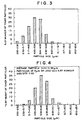
- a toner comprises 17% by number of toner particles with a particle diameter of 5 ⁇ m or less.
- the content of the toner particles with a particle diameter of 5 ⁇ m or less is only 3 wt% of the total weight of the toner particles as shown in FIG. 2.
- those fine toner particles can be selectively deposited to the edge portion of a latent image, and the intermediate toner particles can be selectively deposited to the center portion thereof.
- FIG. 4 is a chart showing the particle size distribution by weight of the same toner shown in FIG. 3.
- the toner particles thus excessively charged are tightly attached to the surface of carrier particles and the surface of the photoconductor. Consequently, the decrease in image density and the fogging are observed in the obtained toner images.
- the surface of the photoconductor cannot be perfectly cleaned, and a filming phenomenon takes place on the surface of the photoconductor.
- Japanese Laid-Open Patent Application 4-1773 discloses a toner comprising toner particles with a particle size of 12.7 to 16.0 ⁇ m in an amount of 0.1 to 5.0 wt% of the total weight of the toner particles in order to improve the fluidity of toner.
- the obtained fluidity of the above-mentioned toner is inferior to that of the toner comprising 1 to 15% by number of toner particles with a particle size of 5 ⁇ m or less.
- the image quality of the obtained toner image tends to become uneven.
- the fluidity of toner can also be improved by increasing the amount of a fluidity imparting agent.
- the fluidity of toner varies depending upon the contact conditions of the fluidity imparting agent with the surface portions of the toner particles.
- the amount of fluidity imparting agent is required to increase 1.5 to 2.0 times the amount thereof necessary for the toner containing 17% by number of the toner particles with a particle size of 5 ⁇ m or less in order to obtain substantially the same fluidity.
- the contamination of the photoconductor and the filming phenomenon on the surface of the photoconductor, and the deterioration of image fixing performance are unavoidable when such a large quantity of fluidity imparting agent is added to the toner particles.
- a first object of the present invention is to provide a toner with high fluidity even though the amount of additive is small, and with excellent image fixing properties, which toner can minimize the contamination and the filming phenomenon of the photoconductor.
- a second object of the present invention is to provide a two-component developer comprising a toner with high fluidity even though the amount of additive is small, and with excellent image fixing properties, which toner can minimize the contamination and the filming phenomenon of the photoconductor.
- a third object of the present invention is to provide a toner cartridge for holding the above-mentioned toner.
- a fourth object of the present invention is to provide an image formation method with minimum deterioration of the developer and minimum abrasion of the photoconductor, free of defective cleaning and unfavorable filming of the photoconductor even though large quantities of copies or printings are made at high speed for an extended period of time.
- a fifth object of the present invention is to provide an image formation apparatus with minimum deterioration of the developer and minimum abrasion of the photoconductor, free of defective cleaning and unfavorable filming of the photoconductor even though large quantities of copies or printings are made at high speed for an extended period of time.
- the first object of the present invention can be achieved by a toner comprising toner particles which comprise a binder resin and a coloring agent, wherein the toner particles have a weight-average particle diameter in a range of 6.0 to 11.5 ⁇ m, and comprise toner particles (a) with a particle diameter of 5 ⁇ m or less in a content ratio of 1 to 15% by number, and toner particles (b) with a particle diameter of twice or more the weight-average particle size in a content ratio of 5 wt% or less, and satisfy the conditions that a number-average particle size D25 when the cumulative number of the toner particles reaches 25% at the measurement of a cumulative toner particle distribution by number thereof, and a number-average particle size D75 when the cumulative number of the toner particles reaches 75% at the measurement of the cumulative toner particle distribution by number thereof are in the relationship of 0.60 ⁇ D25/D75 ⁇ 0.85.
- the first object of the present invention can also be achieved by a toner comprising toner particles which comprise a binder resin and a coloring agent, wherein the toner particles have a weight-average particle size in a range of 6.0 to 9.5 ⁇ m, and comprise toner particles (a) with a particle diameter of 5 ⁇ m or less in a content ratio of 1 to 12% by number, and toner particles (b) with a particle diameter of twice or more the weight-average particle size in a content ratio of 3 wt% or less, and satisfy the aforementioned relationship of 0.70 ⁇ D25/D75 ⁇ 0.85.
- the binder resin comprise a polyol resin or a polyester resin.
- the toner may further comprise a magnetic material.
- the second object of the present invention can be achieved by a two-component developer comprising a toner and a carrier, the toner comprising toner particles which comprise a binder resin and a coloring agent, wherein the toner particles have a weight-average particle size in a range of 6.0 to 11.5 ⁇ m, and comprise toner particles (a) with a particle diameter of 5 ⁇ m or less in a content ratio of 1 to 15% by number, and toner particles (b) with a particle diameter of twice or more the weight-average particle size in a content ratio of 5 wt% or less, and satisfy the conditions that a number-average particle size D25 when the cumulative number of the toner particles reaches 25% at the measurement of a cumulative toner particle distribution by number thereof, and a number-average particle size D75 when the cumulative number of the toner particles reaches 75% at the measurement of the cumulative toner particle distribution by number thereof are in the relationship of 0.60 ⁇ D25/D75 ⁇ 0.85.
- the carrier for use in the two-component developer comprise magnetic carrier particles with a weight-average particle size of 35 to 100 ⁇ m, more preferably 45 to 75 ⁇ m.
- the third object of the present invention can be achieved by a toner cartridge holding therein the above-mentioned toner.
- the fourth object of the present invention can be achieved by an image formation method comprising the steps of forming a latent image on a latent image bearing member, developing the latent image to a visible image with the above-mentioned toner, transferring the visible image to an image receiving material, and cleaning the toner remaining on the latent image bearing member.
- the latent image bearing member be an organic photoconductor belt, and the latent image bearing member be cleaned with a rotational cleaning brush in the form of a roll.
- the fifth object of the present invention can be achieved by an image formation apparatus capable of forming a toner image, using the above-mentioned toner.
- FIG. 1 is a chart showing one example of the particle size distribution of a conventional toner which contains 17% by number of toner particles with a particle diameter of 5 ⁇ m or less.
- FIG. 2 is a chart showing the particle size distribution of the conventional toner shown in FIG. 1, which particle size distribution is expressed by the weight percentage.
- FIG. 3 is a chart showing another example of the particle size distribution of a conventional toner which contains 60% by number of toner particles with a particle diameter of 5 ⁇ m or less.
- FIG. 4 is a chart showing the particle size distribution of the conventional toner shown in FIG. 3, which particle size distribution is expressed by the weight percentage.
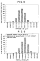
- FIG. 5 is a chart showing one example of the particle size distribution of a toner according to the present invention, which particle size distribution is expressed by the percentage by number.
- FIG. 6 is a chart showing the particle size distribution of the toner according to the present invention shown in FIG. 5, which particle size distribution is expressed by the weight percentage.
- FIG. 7 is a cross-sectional schematic view of a full-color copying machine employed in Example 9.
- the toner of the present invention which shows such a particle size distribution as in FIG. 5 and FIG. 6, exhibits excellent fluidity even though the amount of a fluidity imparting agent, such as finely-divided inorganic particles which have been treated to be hydrophobic is small.
- a fluidity imparting agent such as finely-divided inorganic particles which have been treated to be hydrophobic is small.
- the toner contains 1 to 15%, preferably 1 to 12%, and more preferably 3 to 12%, by number of toner particles with a particle diameter of 5 ⁇ m or less.
- the average particle diameter of the toner particles is relatively decreased.
- a small average particle diameter of toner particles is advantageous in the formation of a toner image with high preciseness and high resolution.
- fine toner particles with a particle diameter of 5 ⁇ m or less are difficult to control the charge quantity, and likely to lower the fluidity of toner particles and contaminate the carrier. Further, those fine toner particles tend to cause the defective cleaning problem and toner filming phenomenon on the surface of the photoconductor, and tend to easily scatter to stain the inside of the image formation apparatus.
- the increase in the content of fine toner particles with a particle diameter of 5 ⁇ m or less cannot solve the above-mentioned problems although those particles have a good effect on the improvement of the resolution in the obtained toner images. Therefore, excessive increase of those fine toner particles is considered to be disadvantageous in light of the long-term service of the toner as a two-component developer.
- the proper fluidity of toner particles can be ensured with the addition of a small amount of the fluidity imparting agent such as inorganic oxide powders because the number of toner particles with a particle diameter of 5 ⁇ m or less is controlled to 1 to 15% of the entire number of toner particles.
- the contamination of the photoconductor and the occurrence of filming phenomenon can be thus prevented in practice, and the image fixing performance is improved.
- the weight average particle size of the toner particles is in the range of 6.0 to 11.5 ⁇ m, it is difficult to control the content of the fine toner particles with a particle diameter of 5 ⁇ m or less to 0% from the viewpoint of productivity. Therefore, the content of the fine toner particles with a particle diameter of 5 ⁇ m or less is controlled to 1% or more, preferably 3% or more in the present invention.
- the second feature of the toner according to the present invention is that the number-average particle size D25 and the number-average particle size D75 are in a relationship of 0.60 ⁇ D25/D75 ⁇ 0.85, more preferably 0.70 ⁇ D25/D75 ⁇ 0.85.
- the number-average particle size D25 is a particle size obtained when the cumulative number of the toner particles reaches 25% at the measurement of a cumulative toner particle distribution by number thereof
- the number-average particle size D75 is a particle size obtained when the cumulative number of the toner particles reaches 75% at the measurement of the cumulative toner particle distribution by number thereof.
- the particle size distribution of toner particles becomes sharper within the range from 25 to 75% in the cumulative particle size distribution by number.
- the properties of each of toner particles within the above-mentioned range can be made uniform. Owing to the uniform behavior of each toner particle in the development unit, toner images with high preciseness and high resolution can be constantly produced with minimum selective consumption of toner particles and minimum variance of charge quantity of the toner.
- the content of toner particles whose particle diameter is twice or more the weight-average particle size is controlled to 5 wt% or less, preferably 3 wt% or less, of the total weight of the toner particles.
- the results become more preferable.
- the toner contains the above-mentioned toner particles in an amount of more than 5 wt%, the reproducibility of a thin line image tends to decrease.
- the weight-average particle size of the toner of the present invention is in the range of 6.0 to 11.5 ⁇ m, preferably in the range of 6.0 to 9.5 ⁇ m.
- the weight-average particle size is less than 6.0 ⁇ m, there easily occur the problems that the inside of the image forming apparatus is contaminated due to scattering of toner particles during the long-term service, the image density decreases under the circumstances of low humidity, and the cleaning of the photoconductor is defective.
- the weight-average particle size exceeds 11.5 ⁇ m, the resolution of a minute spot with a diameter of 100 ⁇ m or less is not sufficient, and the toner particles are scattering in the non-image area (background area), thereby lowering the image quality.
- the toner of the present invention can exhibit the excellent performance as previously mentioned when used as a magnetic toner or a non-magnetic toner, and further, used as a mono-component developer or a two-component developer.
- the two-component developer according to the present invention comprises the above-mentioned toner and a carrier comprising magnetic carrier particles.
- the average particle size of the magnetic carrier particles be in the range of 35 to 100 ⁇ m, and more preferably in the range of 45 to 75 ⁇ m.
- the charge quantity of toner can be made more uniform under the conditions that the concentration of toner in the developer is controlled to 2 to 10 wt% in a developer unit.
- the weight-average particle size of the carrier particles is 35 ⁇ m or more, the carrier particles can be prevented from being attracted to the photoconductor, and can be stirred with the toner particles efficiently to provide the toner with uniform charge quantity.
- the weight-average particle size of the carrier particles is 100 ⁇ m or less, the carrier particles can charge the toner particles sufficiently, so that uniform charge quantity of toner can be obtained.
- the developer of the present invention can not only solve the conventional problems, but also meet the strict requirements of the currently employed high-speed image formation apparatus, that is, the elevation of image quality, the reduction of image fixing temperature, and the improvement of durability of the employed photoconductor.
- the weight-average particle size of the carrier particles can be measured by the conventional sieving method.
- 200 to 400 carrier particles are selected by random sampling from a microphotographic image taken by an optical microscope, and subjected to image processing analysis to obtain the weight-average particle size of those particles.
- the particle size distribution of the toner particles is measured using a commercially available measuring apparatus "Coulter Counter Model TA II” (Trademark), made by Coulter Electronics Limited in the present invention.
- the particle size distributions by number and by weight are output using the measuring apparatus of 'Coulter Counter Model TA II", and analyzed using a personal computer 'PC9801", made by NEC Corporation, that is connected to the 'Coulter Counter Model TA II".
- a 1% aqueous solution of sodium chloride is prepared using a first class grade chemical of NaCl.
- a surfactant preferably alkylbenzene sulfonate, serving as a dispersant
- a sample toner particles in an amount of 2 to 20 mg is added.
- the mixture thus prepared is subjected to ultrasonic dispersion process for about 1 to 3 minutes.
- the dispersion thus prepared is added to 100 to 200 ml of a 1% aqueous solution of sodium chloride separately prepared in a beaker to obtain a predetermined concentration of the sample dispersion.
- the particle distribution of toner particles with a particle size ranging from 2 to 40 ⁇ m is measured using 50,000 particles. The distributions of those particles by weight and by number are calculated. From the particle distribution by weight, the weight-average particle size is obtained.
- the toner having such particle size distribution as specified in the present invention it is desirable to add finely-divided inorganic particles as a fluidity imparting agent to the toner.
- the specific surface area of the toner is smaller than that of the conventional toner. Therefore, when the toner of the present invention is mixed with a magnetic carrier to prepare a two-component developer, the possibility of bringing the toner particles in contact with the carrier particles is decreased as compared with the case of the conventional two-component developer. As a result, the carrier particles can be prevented from being contaminated with the toner, and the toner particles can be prevented from being abraded and crushed.
- the amount of finely-divided inorganic particles added to the toner as the fluidity imparting agent can be decreased. Accordingly, it is possible to minimize the contamination of the photoconductor with the finely-divided inorganic particles, the filming phenomenon, and defective image fixing. Therefore, the life of the developer and that of the photoconductor can be extended.
- the toner particles with a number-average particle size ranging from D25 to D75 which play a significant role, can exhibit their function more effectively when used in combination with a small amount of the finely-divided inorganic particles, thereby steadily providing high quality toner image for an extended period of time.
- oxides and composite oxides comprising Si, Ti, Al, Mg, Ca, Sr, Ba, In, Ga, Ni, Mn, W, Fe, Co, Zn, Cr, Mo, Cu, Ag, V, and Zr are useful.
- finely-divided particles of silicon dioxide (silica), titanium dioxide (titania) and aluminum oxide (alumina) are particularly preferable.
- the above-mentioned inorganic powders may be surface-treated to make those powders hydrophobic.
- the surface treatment agent for making the inorganic powders hydrophobic are as follows: dimethyldichlorosilane, trimehtylchlorosilane, methyltrichlorosilane, allyldimethyldichlorosilane, allylphenyldichlorosilane, benzyldimethylchlorosilane, bromomethyldimethylchlorosilane, ⁇ -chloroethyltrichlorosilane, p-chloroethyltrichlorosilane, chloromethyldimethylchlorosilane, chloromethyltrichlorosilane, p-chlorophenyltrichlorosilane, 3-chloropropyltrichlorosilane, 3-chloropropyltrimethoxysilane, vinyltriethoxysilane, vinyl
- the amount of inorganic powders be in the range of 0.1 to 2 wt% of the entire weight of the toner.
- the amount of inorganic powders is less than 0.1 wt%, aggregation of toner particles cannot be effectively prevented.
- the amount of inorganic powders exceeds 2 wt%, the toner particles tend to scatter between thin line images, the inside of the image forming apparatus tends to be stained with toner particles, and the photoconductor is easily damaged or abraded.
- the present invention even though the amount of inorganic powders is small, the predetermined fluidity of toner can be ensured. As a result, high quality images with high resolution can be constantly produced when large quantities of copies are made for a long period of time.
- the present invention is obviously effective as compared with the case where the amount of toner particles with a particle diameter of 5 ⁇ m or less is increased and a large quantity of inorganic powders is added.
- the developer of the present invention may further comprise other additives as long as they have an adverse effect on the developer.
- lubricant such as finely-divided particles of Teflon, zinc stearate, and polyvinylidene fluoride
- an abrasive such as finely-divided particles of cerium oxide, silicon carbide and strontium titanate
- an electroconductivity imparting agent such as finely-divided particles of carbon black, zinc oxide and tin oxide
- an agent for improving development performance such as finely-divided white powders and black powders, each having a polarity opposite to that of the toner.
- binder resins for use in the toner of the present any binder resins used in the conventional toners are usable.
- a vinyl resin, a polyester resin, or a polyol resin is preferably employed as the binder resin.
- vinyl resin used as the binder resin for use in the toner include homopolymers of styrene and substituted styrenes such as polystyrene, poly-p-chlorostyrene, and polyvinyltoluene; styrene-based copolymers such as styrene - p-chlorostyrene copolymer, styrene - propylene copolymer, styrene - vinyltoluene copolymer, styrene - vinylnaphthalene copolymer, styrene - methyl acrylate copolymer, styrene - ethyl acrylate copolymer, styrene - butyl acrylate copolymer, styrene - octyl acrylate copolymer, styrene - methyl methacrylate cop
- the polyester resin serving as the binder resin in the present invention is prepared from a dihydroxy alcohol component (a) selected from the following group A and a dibasic acid component (b) selected from the following group B. Furthermore, a polyhydric alcohol having three or more hydroxyl groups, or a polycarboxylic acid having three or more carboxyl groups selected from the following group C may be added to the above-mentioned components (a) and (b).
- Group A ethylene glycol, triethylene glycol, 1,2-propylene glycol, 1,3-propylene glycol, 1,4-butanediol, neopentyl glycol, 1,4-butenediol, 1,4-bis(hydroxymethyl)cyclohexane, bisphenol A, hydrogenated bisphenol A, a reaction product of polyoxyethylene and bisphenol A, polyoxypropylene(2,2)-2,2'-bis(4-hydroxyphenyl)propane, polyoxypropylene(3,3)-2,2-bis(4-hydroxyphenyl)propane, polyoxyethylene(2,0)-2,2-bis(4-hydroxyphenyl)propane, and polyoxypropylene(2,0)-2,2'-bis(4-hydroxyphenyl)propane.
- Group B maleic acid, fumaric acid, mesaconic acid, citraconic acid, itaconic acid, glutaconic acid, phthalic acid, isophthalic acid, terephthalic acid, cyclohexanedicarboxylic acid, succinic acid, adipic acid, sebacic acid, malonic acid, linolenic acid; anhydrides of the above acids; and esters of the above acids and a lower alcohol.
- Group C polyhydric alcohols having three or more hydroxyl groups, such as glycerin, trimethylolpropane, and pentaerythritol; and polycarboxylic acids having three or more carboxyl groups, such as trimellitic acid and pyromellitic acid.
- the polyol resin which is preferably used as the binder resin in the toner of the present invention is prepared by allowing the following components to react: (1) an epoxy resin; (2) an alkylene oxide adduct of a dihydric phenol or a glycidyl ether of the alkylene oxide adduct; (3) a compound having in the molecule thereof one active hydrogen atom which is capable of reacting with epoxy group; and (4) a compound having in the molecule thereof two or more active hydrogen atoms which are capable of reacting with epoxy group.
- the above-mentioned resins may be used together with other resins, for example, epoxy resin, polyamide resin, urethane resin, phenolic resin, butyral resin, rosin, modified rosin, and terpene resin when necessary.
- epoxy resin for use in the present invention, a polycondensation product of a bisphenol such as bisphenol A or bisphenol F and epichlorohydrin is representative.
- the coloring agent for use in the toner of the present invention includes a variety of pigments.
- black coloring agent examples include carbon black, oil furnace black, channel black, lamp back, acetylene black, Azine dyes such as aniline black, metallic salt azo dyes, metallic oxides, and composite metallic oxides.
- yellow pigment examples include Cadmium Yellow, Mineral Fast Yellow, Nickel Titan Yellow, Naples Yellow, Naphthol Yellow S, Hansa Yellow G, Hansa Yellow 10G, Benzidine Yellow GR, Quinoline Yellow Lake, Permanent Yellow NCG, and Tartrazine Lake.
- orange pigment examples include Molybdate Orange, Permanent Orange GTR, Pyrazolone Orange, Vulcan Orange, Indanthrene Brilliant Orange RK, Benzidine Orange G, and Indanthrene Brilliant Orange GK.
- red pigment examples include red iron oxide, Cadmium Red, Permanent Red 4R, Lithol Red, Pyrazolone Red, Watchung Red Calcium Salt, Lake Red D, Brilliant Carmine 6B, Eosine Lake, Rhodamine Lake B, Alizarine Lake, and Brilliant Carmine 3B.
- purple pigment examples include Fast Violet B and Methyl Violet Lake.
- blue pigment examples include Cobalt Blue, Alkali Blue, Victoria Blue Lake, Phthalocyanine Blue, metal-free Phthalocyanine Blue, Phthalocyanine Blue partially chlorinated, Fast Sky Blue and Indanthrene Blue BC.
- green pigment examples include Chrome Green, chromium oxide, Pigment Green B, and Malachite Green Lake.
- These pigments can be employed alone or in combination.
- any conventional dyes may be used as the coloring agents in the present invention.
- the toner of the present invention may further comprise a releasing agent for inhibiting the off-set phenomenon in the image fixing process.
- the releasing agent may be internally added to the toner composition.
- Examples of the releasing agent include natural waxes such as candelilla wax, carnauba wax, and rice wax; montan wax, paraffin wax, sazol wax, low-molecular-weight polyethylene, low-molecular-weight polypropylene, and alkyl phosphate.
- the releasing agent may be determined depending upon the kind of binder resin for use in the toner and the kind of material used for the surface portion of the image fixing roller. It is preferable that the melting point of the employed releasing agent be in the range of 65 to 90°C. When the melting point of the releasing agent is within the above-mentioned range, blocking of toner particles can be prevented during the storage thereof, and the off-set phenomenon does not easily take place when the image fixing roller is in a low temperature region.
- the two-component developer according to the present invention may further comprise a charge control agent.
- the charge control agent may be incorporated in the toner particles (internal addition), or may be mixed with the toner particles (external addition).
- the charge control agent makes it possible to appropriately control the charge quantity of toner depending on the employed development system. By the addition of the charge control agent, the balance between the charge quantity of toner and the particle size distribution can be stabilized.
- positive charge control agent examples include nigrosine, quaternary ammonium salts, and imidazole metal complexes and salts thereof; and specific examples of the negative charge control agent are salicylic acid metal complexes and salts thereof, organic boron salts, and calixarene compounds.
- the toner of the present invention is employed as a magnetic toner
- finely-divided particles of a magnetic material may be dispersed in the toner particle.
- the magnetic material examples include ferromagnetic metals, such as iron, nickel and cobalt, and alloys and compounds comprising the above-mentioned elements, such as ferrite and magnetite; alloys capable of exhibiting ferromagnetism by proper heat treatment although the ferromagnetic elements are not contained, such as the so-called Heusler's alloys comprising manganese and copper (a manganese - copper - aluminum alloy, and a manganese - copper - tin alloy); and chromium dioxide.
- ferromagnetic metals such as iron, nickel and cobalt
- alloys and compounds comprising the above-mentioned elements such as ferrite and magnetite
- alloys capable of exhibiting ferromagnetism by proper heat treatment although the ferromagnetic elements are not contained such as the so-called Heusler's alloys comprising manganese and copper (a manganese - copper - aluminum alloy, and a manganese - copper - tin
- the magnetic material be in the form of finely-divided particles with an average particle size of 0.1 to 1 ⁇ m. Those magnetic particles may be uniformly dispersed in the toner composition. It is preferable that the amount of magnetic material be in the range of 10 to 70 parts by weight, more preferably in the range of 20 to 50 parts by weight, with respect to 100 parts by weight of the obtained toner.
- the carrier for use in the two-component developer of the present invention there can be used any materials for the conventional carriers.
- magnetic powders such as iron powder, ferrite powder, nickel powder, and magnetite powder are useful, and these magnetic powders may be surface-treated with a fluorine-containing resin, vinyl resin or silicone resin.
- resin particles prepared by dispersing the magnetic powders in a resin are also employed as the carrier particles. It is proper that the weight-average particle size of the magnetic carrier particles be in the range of 35 to 75 ⁇ m.
- a toner according to the present invention can be prepared, for example, by sufficiently mixing the above-mentioned binder resin, pigment or dye serving as the coloring agent, lubricant, and other additives using a mixer such as a Henschel mixer, and thoroughly kneading the mixture.
- the following kneaders can be appropriately employed: a batch-type two-roll mixer, Banburry's mixer, a continuous double screw extruder such as a KTK type double screw extruder made by Kobe Steel, Ltd., a TEM type double screw extruder made by Toshiba Machine Co., Ltd., a double screw extruder made by KCK Co., Ltd., a PCM type double screw extruder made by Ikegai Tekko Co., Ltd., a KEX type double screw extruder made by Kurimoto, Ltd., and a continuous single screw kneader, for example, Continuous Kneader made by Buss Co., Ltd.
- a continuous double screw extruder such as a KTK type double screw extruder made by Kobe Steel, Ltd., a TEM type double screw extruder made by Toshiba Machine Co., Ltd., a double screw extruder made by KCK Co., Ltd., a PCM type double screw extruder made by Ikega
- the mixture is coarsely crushed by a hammer mill, and thereafter finely pulverized by means of a pulverizer using jet air stream or a mechanical pulverizer, and classified to obtain a predetermined particle size using a rotary air classifier or a classifier utilizing a Coanda effect.
- the classified particles are sufficiently mixed with the above-mentioned finely-divided inorganic particles in a mixer such as a Henschel mixer, and the obtained particles are caused to pass through a sieve with 250-mesh or more to remove the coarse particles and the aggregated particles.
- a toner according to the present invention is obtained.
- the thus obtained toner and the above-mentioned magnetic carrier are mixed at a predetermined mixing ratio, so that a two-component developer according to the present invention is obtained.
- Parts by Weight Binder resin polyol resin 100 Coloring agent: carbon black 10 Charge control agent; zinc salicylate 5 Releasing agent: low molecular weight polyethylene 5
- the resultant mixture was fused and kneaded at 120°C using a double-screw extruder. After the kneaded mixture was rolled and cooled, the mixture was coarsely crushed by a cutter mill and finely pulverized by means of a pulverizer using jet air stream. Thereafter, the particles were subjected to air classification so as to obtain such particle size distribution as shown in TABLE 1. Thus, matrix toner particles were prepared.
- 100 parts by weight of the matrix toner particles were mixed with 0.3 parts by weight of hydrophobic silica particles in a Henschel mixer, whereby a toner (1) according to the present invention was obtained.
- the loose bulk density and the cohesiveness were measured using a commercially available powder characteristics tester "Powder Tester PT-N" (Trademark), made by Hosokawa Micron Corporation.
- the loose bulk density was measured by screening the toner particles. To be more specific, the toner particles passing through a 250-mesh screen and going to a hopper were collected and weighed. The loose bulk density was calculated from the weight thus obtained.
- the cohesiveness was measured by subjecting the toner particles to screening using the standard sieves of 150- ⁇ m mesh, 75- ⁇ m mesh, and 45- ⁇ m mesh, with the application of vibration for 60 sec. Then, the cohesiveness was calculated in accordance with the following formula:
- the thus obtained two-component developer No. 1 was set in a commercially available copying apparatus "imagio DA505" (Trademark), made by Ricoh Company, Ltd., which was provided with an organic photoconductor drum as the latent image bearing member and a cleaning blade as the cleaning means.
- imagio DA505" Trademark
- Ricoh Company, Ltd. which was provided with an organic photoconductor drum as the latent image bearing member and a cleaning blade as the cleaning means.
- the two solid image samples produced at different image fixing temperatures were subjected to scratch test using a commercially available tester. Each solid image was rubbed with a needle with the application of a load of 50 g thereto, and thereafter the remaining scratch was visually observed.
- the image fixing performance was evaluated on the scale from 1 to 5. The greater the scale value, the better the image fixing performance.
- the scale value of less than 3 is regarded as unacceptable for practical use. This is because such a remaining image sample is easily peeled off when rubbed with an eraser. Image fixing performance is excellent at the scale value of 5.
- the decrease in thickness of the photoconductor was obtained. To be more specific, the thickness of the photoconductor was measured at 30 points thereof using an eddy-current type film thickness measuring apparatus before and after the running test of 800,000 copies. The decrease in film thickness on the average was obtained.
- Example 1 The procedure for preparation of the two-component developer in Example 1 was repeated except that the weight-average particle size of the employed carrier particles was changed from 100 ⁇ m to 30 ⁇ m.
- the two-component developer No. 2 was evaluated in the same manner as in Example 1.
- Example 1 The procedure for preparation of the two-component developer in Example 1 was repeated except that the weight-average particle size of the employed carrier particles was changed from 100 ⁇ m to 50 ⁇ m.
- the two-component developer No. 3 was evaluated in the same manner as in Example 1.
- Example 2 The procedure for preparation of the toner (1) in Example 1 was repeated except that the conditions of classification were changed so as to obtain such a particle size distribution as shown in TABLE 1, and that the amount of hydrophobic silica was changed from 0.3 to 0.5 parts by weight. Thus, a toner (2) of the present invention was prepared.
- the two-component developer No. 4 was evaluated in the same manner as in Example 1.
- Example 1 The procedure for preparation of the toner (1) in Example 1 was repeated except that the conditions of classification were changed so as to obtain such a particle size distribution as shown in TABLE 1, and that the amount of hydrophobic silica was changed from 0.3 to 0.5 parts by weight. Thus, a toner (3) of the present invention was prepared.
- the two-component developer No. 5 was evaluated in the same manner as in Example 1.
- Example 1 The procedure for preparation of the toner (1) in Example 1 was repeated except that the conditions of classification were changed so as to obtain such a particle size distribution as shown in TABLE 1, and that the amount of hydrophobic silica was changed from 0.3 to 0.5 parts by weight. Thus, a toner (4) of the present invention was prepared.
- the two-component developer No. 6 was evaluated in the same manner as in Example 1.
- Binder resin styrene-methylacrylate copolymer 100 Coloring agent: carbon black 10 Charge control agent: nigrosine 5
- the resultant mixture was fused and kneaded at 110°C using a double-screw extruder. After the kneaded mixture was rolled and cooled, the mixture was coarsely crushed by a cutter mill and finely pulverized by means of a pulverizer using jet air stream. Thereafter, the particles were subjected to air classification so as to obtain such a particle size distribution as shown in TABLE 1. Thus, matrix toner particles were prepared.
- the thus obtained two-component developer No. 7 was set in a commercially available copying apparatus "FT9001II” (Trademark), made by Ricoh Company, Ltd., which was provided with an organic photoconductor in the form of a belt as the latent image bearing member and a magnetic brush as the cleaning means.
- FT9001II Commercially available copying apparatus
- Example 7 The procedure for preparation of the toner (5) in Example 7 was repeated except that the conditions of classification were changed so as to obtain such a particle size distribution as shown in TABLE 1. Thus, a toner (6) of the present invention was prepared.
- the two-component developer No. 8 was evaluated in the same manner as in Example 7.
- Binder resin polyester resin 100 Coloring agent; quinacridone based magenta pigment (C.I. Pigment Red 122) 8 Charge control agent: zinc salicylate 3
- the resultant mixture was fused and kneaded at 120°C using a double-screw extruder. After the kneaded mixture was rolled and cooled, the mixture was coarsely crushed by a cutter mill and finely pulverized by means of a pulverizer using jet air stream. Thereafter, the particles were subjected to air classification so as to obtain such a particle size distribution as shown in TABLE 1. Thus, matrix toner particles were prepared.
- 100 parts by weight of the matrix toner particles were mixed with 0.3 parts by weight of hydrophobic silica particles in a Henschel mixer, whereby a toner (7) according to the present invention was obtained.
- the thus obtained two-component developer No. 9 was set in a commercially available full-color copying apparatus "PRETER 550" (Trademark), made by Ricoh Company, Ltd.
- FIG. 7 is a schematic cross-sectional view of the above-mentioned full-color copying apparatus.
- reference numeral 101 indicates a scanners reference numeral 201, a copying apparatus; reference numeral 202, a black development unit; reference numeral 203, a cyan development unit; reference numeral 204, a magenta development unit; reference numeral 205, a yellow development unit; reference numeral 206, an intermediate image transfer belt; reference numeral 207, a charging unit; reference numeral 208, an optical laser system; reference numeral 209, a contact glass; reference numeral 210, an exposure lamp (halogen lamp); reference numeral 211, a reflector; reference numeral 212, an image formation lens; reference numeral 213, a CCD image sensor; reference numeral 214, a cleaning unit; reference numeral 215, a photoconductor; reference numeral 216, a paper feed unit; reference numeral 217, an image transfer bias roller; reference numeral 218, a transporting belt; reference nume
- Binder resin polyester resin 100 Coloring agent: copper phthalocyanine blue pigment (C.I. Pigment Blue 15:3) 3.5 Charge control agent; zinc salicylate 5
- the resultant mixture was fused and kneaded at 120°C using a double-screw extruder. After the kneaded mixture was rolled and cooled, the mixture was coarsely crushed by a cutter mill and finely pulverized by means of a pulverizer using jet air stream. Thereafter, the particles were subjected to air classification so as to obtain such a particle size distribution as shown in TABLE 1. Thus, matrix toner particles were prepared.
- toner (8) that is, a mono-component color developer was set in a commercially available printer "SF10PS ProII” (Trademark), made by Ricoh Company, Ltd.
- Binder resin styrene-methyl acrylate copolymer 100
- Magnetic material Fe 2 O 3 80
- Charge control agent zinc salicylate 4
- the resultant mixture was fused and kneaded at 120°C using a double-screw extruder. After the kneaded mixture was rolled and cooled, the mixture was coarsely crushed by a cutter mill and finely pulverized by means of a pulverizer using jet air stream. Thereafter, the particles were subjected to air classification so as to obtain such a particle size distribution as shown in TABLE 1. Thus, matrix toner particles were prepared.
- the thus obtained magnetic toner (9), that is, a mono-component developer was set in a commercially available printer "SP10PS ProII” (Trademark), made by Ricoh Company, Ltd.
- Example 1 The procedure for preparation of the toner (1) in Example 1 was repeated except that the conditions of classification were changed so as to obtain such a particle size distribution as shown in TABLE 1, and that the amount of hydrophobic silica was changed from 0.3 to 0.5 parts by weight. Thus, a toner (10) was prepared.
- the comparative two-component developer No. 1 was evaluated in the same manner as in Example 1.
- Example 1 The procedure for preparation of the toner (1) in Example 1 was repeated except that the conditions of classification were changed so as to obtain such a particle size distribution as shown in TABLE 1, and that the amount of hydrophobic silica was changed from 0.3 to 0.7 parts by weight. Thus, a toner (11) was prepared.
- the comparative two-component developer No. 2 was evaluated in the same manner as in Example 1.
- Example 2 The procedure for preparation of the toner (1) in Example 1 was repeated except that the conditions of classification were changed so as to obtain such a particle size distribution as shown in TABLE 1, and that the amount of hydrophobic silica was changed from 0.3 to 3.0 parts by weight. Thus, a toner (12) was prepared.
- the comparative two-component developer No. 3 was evaluated in the same manner as in Example 1.
- Example 1 The procedure for preparation of the toner (1) in Example 1 was repeated except that the conditions of classification were changed so as to obtain such a particle size distribution as shown in TABLE 1, and that the amount of hydrophobic silica was changed from 0.3 to 1.0 parts by weight. Thus, a toner (13) was prepared.
- the comparative two-component developer No. 4 was evaluated in the same manner as in Example 1.
- Example 1 The procedure for preparation of the toner (1) in Example 1 was repeated except that the conditions of classification were changed so as to obtain such a particle size distribution as shown in TABLE 1. Thus, a toner (14) was prepared.
- the comparative two-component developer No. 5 was evaluated in the same manner as in Example 1.
- Example 1 The procedure for preparation of the toner (1) in Example 1 was repeated except that the conditions of classification were changed so as to obtain such a particle size distribution as shown in TABLE 1. Thus, a toner (15) was prepared.
- the comparative two-component developer No. 6 was evaluated in the same manner as in Example 1.
- Example 1 The procedure for preparation of the toner (1) in Example 1 was repeated except that the conditions of classification were changed so as to obtain such a particle size distribution as shown in TABLE 1.
- the yield of matrix toner particles was as low as 21% under the above-mentioned classification conditions, which yield was not considered to be acceptable for practical use.
- the comparative two-component developer No. 7 was evaluated in the same manner as in Example 1.
- Example 7 The procedure for preparation of the toner (5) in Example 7 was repeated except that the conditions of classification were changed so as to obtain such a particle size distribution as shown in TABLE 1. Thus, a toner (17) was prepared.
- the comparative two-component developer No. 8 was evaluated in the same manner as in Example 7.
- the comparative two-component developer No. 9 was evaluated in the same manner as in Example 7.
- the toner or two-component developer according to the present invention exhibits excellent fluidity even though the amount of additive for improving the fluidity of toner particles is small, and does not cause the contamination of the employed photoconductor and the filming phenomenon. Thus, it becomes possible to produce hard copy images with high image fixing performance, high image density, high resolution, and high preciseness.
Landscapes
- Physics & Mathematics (AREA)
- General Physics & Mathematics (AREA)
- Developing Agents For Electrophotography (AREA)
Applications Claiming Priority (4)
| Application Number | Priority Date | Filing Date | Title |
|---|---|---|---|
| JP31986098 | 1998-10-26 | ||
| JP31986098 | 1998-10-26 | ||
| JP6748999 | 1999-03-12 | ||
| JP6748999 | 1999-03-12 |
Publications (2)
| Publication Number | Publication Date |
|---|---|
| EP0997786A1 true EP0997786A1 (fr) | 2000-05-03 |
| EP0997786B1 EP0997786B1 (fr) | 2004-01-07 |
Family
ID=26408710
Family Applications (1)
| Application Number | Title | Priority Date | Filing Date |
|---|---|---|---|
| EP99308474A Revoked EP0997786B1 (fr) | 1998-10-26 | 1999-10-26 | Toner, révélateur à deux composants pour procédé électrophotographique et méthode de formation d'images et appareil de formation d'images l'utilisant |
Country Status (4)
| Country | Link |
|---|---|
| US (1) | US6183926B1 (fr) |
| EP (1) | EP0997786B1 (fr) |
| DE (1) | DE69914042T2 (fr) |
| ES (1) | ES2213332T3 (fr) |
Cited By (1)
| Publication number | Priority date | Publication date | Assignee | Title |
|---|---|---|---|---|
| EP1055970A1 (fr) * | 1999-05-28 | 2000-11-29 | Ricoh Company, Ltd. | Révélateur à deux composants, récipient de révélateur, méthode de formation d'images et appareil de formation d'images l'utilisant |
Families Citing this family (49)
| Publication number | Priority date | Publication date | Assignee | Title |
|---|---|---|---|---|
| US6472118B1 (en) | 1999-11-17 | 2002-10-29 | Ricoh Company, Ltd | Carrier for developer for electrophotography |
| US6395443B2 (en) * | 1999-11-29 | 2002-05-28 | Ricoh Company, Ltd. | Toner for developing electrostatic image and process of preparing same |
| DE60120556T2 (de) | 2000-05-23 | 2007-06-06 | Ricoh Co., Ltd. | Zwei-Komponenten-Entwickler, ein mit diesem Entwickler gefüllter Behälter, und Bilderzeugungsvorrichtung |
| JP4416965B2 (ja) | 2000-06-26 | 2010-02-17 | 株式会社リコー | 静電荷像現像用カラートナー及び定着方法、トナー容器、画像形成装置 |
| JP3925899B2 (ja) | 2000-08-24 | 2007-06-06 | 株式会社リコー | トナー及びトナーの製造方法 |
| JP3963638B2 (ja) | 2000-09-07 | 2007-08-22 | 株式会社リコー | 画像形成装置 |
| US6611672B2 (en) | 2000-09-26 | 2003-08-26 | Ricoh Company, Ltd. | Image forming apparatus, monocolor image forming apparatus, toner recycling apparatus and intermediate transfer member |
| DE60118486T2 (de) | 2000-09-28 | 2006-11-23 | Ricoh Company, Ltd. | Toner, Entwickler und Behälter für den Entwickler und Verfahren sowie Apparat für Bildformung |
| JP4107817B2 (ja) | 2000-09-29 | 2008-06-25 | 株式会社リコー | 画像形成用トナー、画像形成方法及び画像形成装置 |
| JP4360589B2 (ja) | 2000-10-20 | 2009-11-11 | 株式会社リコー | 二成分現像剤、及びそれを使用する画像形成装置、画像形成方法 |
| JP4093446B2 (ja) | 2000-11-06 | 2008-06-04 | 株式会社リコー | 電子写真用トナー外添剤、その製造方法、電子写真用トナー及び電子写真現像装置 |
| US6501121B1 (en) | 2000-11-15 | 2002-12-31 | Motorola, Inc. | Semiconductor structure |
| US6653037B2 (en) | 2000-11-20 | 2003-11-25 | Ricoh Company, Ltd. | Toner for developing latent electrostatic images, and image forming method and device |
| JP3933385B2 (ja) | 2000-11-28 | 2007-06-20 | 株式会社リコー | 静電潜像現像用トナー及び画像形成方法 |
| JP3912649B2 (ja) | 2000-11-30 | 2007-05-09 | 株式会社リコー | 画像形成用トナー、画像形成方法および画像形成装置 |
| JP2002278269A (ja) | 2000-12-20 | 2002-09-27 | Ricoh Co Ltd | 画像形成装置 |
| JP2002251033A (ja) | 2001-02-22 | 2002-09-06 | Ricoh Co Ltd | カラートナー、その製造方法及び画像形成方法 |
| EP1237048A1 (fr) | 2001-03-02 | 2002-09-04 | Ricoh Company, Ltd. | Additif externe pour un révélateur électrophotographique, procédé de fabrication, révélateur et appareil de formation d'images |
| US6790575B2 (en) * | 2001-03-22 | 2004-09-14 | Ricoh Company, Ltd. | Two-component developer, image forming apparatus, and image forming method |
| US6858365B2 (en) | 2001-03-23 | 2005-02-22 | Ricoh Company, Ltd. | Toner for developing electrostatic latent image, developing method and developing apparatus |
| US6777149B2 (en) | 2001-03-23 | 2004-08-17 | Ricoh Company Limited | Electrophotographic image forming apparatus and process cartridge, and electrophotographic photoreceptor therefor |
| DE60211995T2 (de) | 2001-04-03 | 2007-01-25 | Ricoh Co., Ltd. | Toner, Zweikomponenten-Entwickler, Bilderzeugungsverfahren und Vorrichtung |
| US6816691B2 (en) | 2001-05-21 | 2004-11-09 | Ricoh Company | Apparatus having endless belt with roughened guide |
| DE60216538T2 (de) | 2001-05-21 | 2007-06-06 | Ricoh Co., Ltd. | Toner, Entwickler und Bildaufzeichnungsverfahren |
| JP2002351209A (ja) * | 2001-05-29 | 2002-12-06 | Oki Data Corp | 画像形成装置 |
| JP4191401B2 (ja) | 2001-09-25 | 2008-12-03 | 株式会社リコー | 電子写真用トナー、画像形成方法、収納容器及び画像形成装置 |
| US6924073B2 (en) * | 2001-12-28 | 2005-08-02 | Ricoh Company, Ltd. | Toner for developing electrostatic latent image, toner cartridge, developer, developer cartridge, image forming method, and image forming apparatus |
| JP4134576B2 (ja) * | 2002-02-28 | 2008-08-20 | コニカミノルタホールディングス株式会社 | 画像形成方法、画像形成装置及びプロセスカートリッジ |
| KR100423459B1 (ko) * | 2002-07-02 | 2004-03-18 | 삼성전자주식회사 | 칼라 화상형성장치 |
| JP2004341252A (ja) * | 2003-05-15 | 2004-12-02 | Ricoh Co Ltd | 電子写真現像剤用キャリア、現像剤、現像装置及びプロセスカートリッジ |
| JP4030937B2 (ja) * | 2003-05-22 | 2008-01-09 | 株式会社リコー | 静電荷像現像用トナーの製造方法、トナー、及び画像形成装置 |
| JP4037329B2 (ja) * | 2003-06-25 | 2008-01-23 | 株式会社リコー | 静電荷像現像用トナー、現像剤、画像形成方法、画像形成装置及びプロセスカートリッジ |
| US7642032B2 (en) * | 2003-10-22 | 2010-01-05 | Ricoh Company, Limited | Toner, developer, image forming apparatus and image forming method |
| US20050227158A1 (en) * | 2004-04-07 | 2005-10-13 | Kabushiki Kaisha Toshiba | Toner for producing wiring board and method of producing wiring board using thereof |
| JP3987065B2 (ja) * | 2004-10-19 | 2007-10-03 | シャープ株式会社 | 2成分現像剤および画像形成方法 |
| US8403149B2 (en) | 2005-11-18 | 2013-03-26 | Ricoh Company, Ltd. | Cyclone classifier, flash drying system using the cyclone classifier, and toner prepared by the flash drying system |
| JP2007156334A (ja) * | 2005-12-08 | 2007-06-21 | Ricoh Co Ltd | 現像装置 |
| JP4749925B2 (ja) * | 2006-04-21 | 2011-08-17 | 株式会社リコー | 画像形成装置、画像形成方法、及びプロセスカートリッジ |
| US8034526B2 (en) * | 2006-09-07 | 2011-10-11 | Ricoh Company Limited | Method for manufacturing toner and toner |
| JP2008102394A (ja) * | 2006-10-20 | 2008-05-01 | Ricoh Co Ltd | キャリア、補給用現像剤、現像装置内現像剤、現像剤補給装置、画像形成装置、プロセスカートリッジ |
| JP4817389B2 (ja) * | 2007-01-15 | 2011-11-16 | 株式会社リコー | 画像形成装置、プロセスカートリッジ、画像形成方法及び電子写真用現像剤 |
| US20080213682A1 (en) * | 2007-03-02 | 2008-09-04 | Akinori Saitoh | Toner for developing electrostatic image, method for producing the toner, image forming method, image forming apparatus and process cartridge using the toner |
| US7901861B2 (en) * | 2007-12-04 | 2011-03-08 | Ricoh Company Limited | Electrophotographic image forming method |
| US8012659B2 (en) * | 2007-12-14 | 2011-09-06 | Ricoh Company Limited | Image forming apparatus, toner, and process cartridge |
| US20090245876A1 (en) * | 2008-03-31 | 2009-10-01 | Kabushiki Kaisha Toshiba | Electrophotographic toner and image forming apparatus |
| US10682626B2 (en) * | 2013-03-14 | 2020-06-16 | Zeomem Sweden Ab | Method for producing a crystalline film of zeolite and/or zeolite like crystals on a porous substrate |
| US10261430B2 (en) * | 2016-01-14 | 2019-04-16 | Samsung Electronics Co., Ltd. | Photoreceptor for electrophotography and image forming apparatus employing the same |
| GB201714269D0 (en) | 2017-09-05 | 2017-10-18 | Hedlund Jonas | Methods for preparing supported zeolite films |
| JP2024085595A (ja) | 2022-12-15 | 2024-06-27 | 株式会社リコー | トナー、現像剤、プロセスカートリッジ、画像形成装置及び画像形成方法。 |
Citations (4)
| Publication number | Priority date | Publication date | Assignee | Title |
|---|---|---|---|---|
| EP0314459A2 (fr) * | 1987-10-26 | 1989-05-03 | Canon Kabushiki Kaisha | Développateur et dispositif de formation d'images |
| EP0330498A2 (fr) * | 1988-02-24 | 1989-08-30 | Canon Kabushiki Kaisha | Révélateur non magnétique |
| EP0541113A1 (fr) * | 1991-11-08 | 1993-05-12 | Canon Kabushiki Kaisha | Révélateur à un composant pour développer des images électrostatiques et méthode de formation d'images |
| EP0606930A2 (fr) * | 1988-11-30 | 1994-07-20 | Mita Industrial Co., Ltd. | Procédé servant à la préparation de particules polymères, procédé de préparation de particules de "toner", et particules préparées selon ces procédés |
Family Cites Families (4)
| Publication number | Priority date | Publication date | Assignee | Title |
|---|---|---|---|---|
| US4980258A (en) | 1988-11-17 | 1990-12-25 | Ricoh Company, Ltd. | Dry type developer for electrophotography |
| US5225303A (en) | 1990-10-05 | 1993-07-06 | Ricoh Company, Ltd. | Dry-type toner including waxes release agent for electrophotography |
| JP3421751B2 (ja) | 1991-12-06 | 2003-06-30 | 株式会社リコー | 静電荷像現像用トナー |
| JPH09106105A (ja) | 1995-08-08 | 1997-04-22 | Ricoh Co Ltd | カラートナー |
-
1999
- 1999-10-25 US US09/425,985 patent/US6183926B1/en not_active Expired - Lifetime
- 1999-10-26 DE DE69914042T patent/DE69914042T2/de not_active Expired - Lifetime
- 1999-10-26 EP EP99308474A patent/EP0997786B1/fr not_active Revoked
- 1999-10-26 ES ES99308474T patent/ES2213332T3/es not_active Expired - Lifetime
Patent Citations (4)
| Publication number | Priority date | Publication date | Assignee | Title |
|---|---|---|---|---|
| EP0314459A2 (fr) * | 1987-10-26 | 1989-05-03 | Canon Kabushiki Kaisha | Développateur et dispositif de formation d'images |
| EP0330498A2 (fr) * | 1988-02-24 | 1989-08-30 | Canon Kabushiki Kaisha | Révélateur non magnétique |
| EP0606930A2 (fr) * | 1988-11-30 | 1994-07-20 | Mita Industrial Co., Ltd. | Procédé servant à la préparation de particules polymères, procédé de préparation de particules de "toner", et particules préparées selon ces procédés |
| EP0541113A1 (fr) * | 1991-11-08 | 1993-05-12 | Canon Kabushiki Kaisha | Révélateur à un composant pour développer des images électrostatiques et méthode de formation d'images |
Cited By (2)
| Publication number | Priority date | Publication date | Assignee | Title |
|---|---|---|---|---|
| EP1055970A1 (fr) * | 1999-05-28 | 2000-11-29 | Ricoh Company, Ltd. | Révélateur à deux composants, récipient de révélateur, méthode de formation d'images et appareil de formation d'images l'utilisant |
| US6258502B1 (en) | 1999-05-28 | 2001-07-10 | Ricoh Company, Ltd. | Two-component developer, two-component developer holding container, and electrophotographic image formation apparatus equipped with the container |
Also Published As
| Publication number | Publication date |
|---|---|
| DE69914042D1 (de) | 2004-02-12 |
| EP0997786B1 (fr) | 2004-01-07 |
| US6183926B1 (en) | 2001-02-06 |
| DE69914042T2 (de) | 2004-10-14 |
| ES2213332T3 (es) | 2004-08-16 |
Similar Documents
| Publication | Publication Date | Title |
|---|---|---|
| EP0997786B1 (fr) | Toner, révélateur à deux composants pour procédé électrophotographique et méthode de formation d'images et appareil de formation d'images l'utilisant | |
| US6258502B1 (en) | Two-component developer, two-component developer holding container, and electrophotographic image formation apparatus equipped with the container | |
| US6200719B1 (en) | Toner, method of producing the toner, image formation method using the toner, and toner container | |
| JP3902104B2 (ja) | 現像用非磁性トナー | |
| JP2000352841A (ja) | トナー、その製造方法および画像形成方法 | |
| JP2000330327A (ja) | 電子写真用現像剤および画像形成方法 | |
| JP7238505B2 (ja) | キャリア、現像剤、画像形成装置及びキャリアの製造方法 | |
| JP4030066B2 (ja) | 電子写真用現像剤および画像形成方法 | |
| JP2003241416A (ja) | 二成分現像剤 | |
| JP5250389B2 (ja) | 電子写真用トナー、およびこれを用いた画像形成方法 | |
| JP4426485B2 (ja) | 静電荷現像トナー用混練物の評価方法 | |
| JP2003228189A (ja) | 静電荷像現像用トナー | |
| JP4198890B2 (ja) | 電子写真用トナー及びその製造方法 | |
| JP4222593B2 (ja) | 電子写真用トナー及び製造方法 | |
| JP5244545B2 (ja) | 電子写真用トナー、およびこれを用いた画像形成方法 | |
| JP2006195493A (ja) | 二成分現像剤 | |
| JP2001312090A (ja) | 二成分現像剤、その製造方法及び画像形成方法 | |
| JP2000267358A (ja) | カラートナー、該カラートナーを使用した画像形成方法、および画像形成装置 | |
| JP5408538B2 (ja) | 電子写真用キャリアの芯材を被覆するための被覆コートの製造方法 | |
| JPH11184164A (ja) | 電子写真用現像剤組成物 | |
| JP2005043918A (ja) | カラートナーとキャリアとからなる2成分現像剤を用いる画像形成装置 | |
| JP2010102054A (ja) | 電子写真用キャリアの芯材を被覆するための被覆コート液の製造方法 | |
| JP2004038021A (ja) | 二成分現像剤 | |
| JP2004212779A (ja) | 静電荷像現像方法 | |
| JP2001222131A (ja) | 静電荷像現像用トナー及びそのトナーの製造方法 |
Legal Events
| Date | Code | Title | Description |
|---|---|---|---|
| PUAI | Public reference made under article 153(3) epc to a published international application that has entered the european phase |
Free format text: ORIGINAL CODE: 0009012 |
|
| 17P | Request for examination filed |
Effective date: 19991125 |
|
| AK | Designated contracting states |
Kind code of ref document: A1 Designated state(s): DE ES FR GB IT NL |
|
| AX | Request for extension of the european patent |
Free format text: AL;LT;LV;MK;RO;SI |
|
| AKX | Designation fees paid |
Free format text: DE ES FR GB IT NL |
|
| 17Q | First examination report despatched |
Effective date: 20011112 |
|
| GRAH | Despatch of communication of intention to grant a patent |
Free format text: ORIGINAL CODE: EPIDOS IGRA |
|
| GRAS | Grant fee paid |
Free format text: ORIGINAL CODE: EPIDOSNIGR3 |
|
| GRAA | (expected) grant |
Free format text: ORIGINAL CODE: 0009210 |
|
| AK | Designated contracting states |
Kind code of ref document: B1 Designated state(s): DE ES FR GB IT NL |
|
| REG | Reference to a national code |
Ref country code: GB Ref legal event code: FG4D |
|
| REF | Corresponds to: |
Ref document number: 69914042 Country of ref document: DE Date of ref document: 20040212 Kind code of ref document: P |
|
| REG | Reference to a national code |
Ref country code: ES Ref legal event code: FG2A Ref document number: 2213332 Country of ref document: ES Kind code of ref document: T3 |
|
| ET | Fr: translation filed | ||
| PLBQ | Unpublished change to opponent data |
Free format text: ORIGINAL CODE: EPIDOS OPPO |
|
| PLBI | Opposition filed |
Free format text: ORIGINAL CODE: 0009260 |
|
| PLAX | Notice of opposition and request to file observation + time limit sent |
Free format text: ORIGINAL CODE: EPIDOSNOBS2 |
|
| 26 | Opposition filed |
Opponent name: BISMANNS H. Effective date: 20041007 Opponent name: SPANDERN, UWE Effective date: 20041007 |
|
| NLR1 | Nl: opposition has been filed with the epo |
Opponent name: BISMANNS H. Opponent name: SPANDERN, UWE |
|
| PLAX | Notice of opposition and request to file observation + time limit sent |
Free format text: ORIGINAL CODE: EPIDOSNOBS2 |
|
| PLBB | Reply of patent proprietor to notice(s) of opposition received |
Free format text: ORIGINAL CODE: EPIDOSNOBS3 |
|
| PLAB | Opposition data, opponent's data or that of the opponent's representative modified |
Free format text: ORIGINAL CODE: 0009299OPPO |
|
| APBM | Appeal reference recorded |
Free format text: ORIGINAL CODE: EPIDOSNREFNO |
|
| APBP | Date of receipt of notice of appeal recorded |
Free format text: ORIGINAL CODE: EPIDOSNNOA2O |
|
| APAH | Appeal reference modified |
Free format text: ORIGINAL CODE: EPIDOSCREFNO |
|
| APBQ | Date of receipt of statement of grounds of appeal recorded |
Free format text: ORIGINAL CODE: EPIDOSNNOA3O |
|
| APAH | Appeal reference modified |
Free format text: ORIGINAL CODE: EPIDOSCREFNO |
|
| APBU | Appeal procedure closed |
Free format text: ORIGINAL CODE: EPIDOSNNOA9O |
|
| PGFP | Annual fee paid to national office [announced via postgrant information from national office to epo] |
Ref country code: DE Payment date: 20121023 Year of fee payment: 14 Ref country code: FR Payment date: 20121031 Year of fee payment: 14 |
|
| PGFP | Annual fee paid to national office [announced via postgrant information from national office to epo] |
Ref country code: GB Payment date: 20121019 Year of fee payment: 14 Ref country code: ES Payment date: 20121019 Year of fee payment: 14 |
|
| PGFP | Annual fee paid to national office [announced via postgrant information from national office to epo] |
Ref country code: NL Payment date: 20121019 Year of fee payment: 14 |
|
| RDAF | Communication despatched that patent is revoked |
Free format text: ORIGINAL CODE: EPIDOSNREV1 |
|
| REG | Reference to a national code |
Ref country code: DE Ref legal event code: R103 Ref document number: 69914042 Country of ref document: DE Ref country code: DE Ref legal event code: R064 Ref document number: 69914042 Country of ref document: DE |
|
| RDAG | Patent revoked |
Free format text: ORIGINAL CODE: 0009271 |
|
| STAA | Information on the status of an ep patent application or granted ep patent |
Free format text: STATUS: PATENT REVOKED |
|
| 27W | Patent revoked |
Effective date: 20130419 |
|
| GBPR | Gb: patent revoked under art. 102 of the ep convention designating the uk as contracting state |
Effective date: 20130419 |
|
| REG | Reference to a national code |
Ref country code: DE Ref legal event code: R107 Ref document number: 69914042 Country of ref document: DE Effective date: 20130725 |
|
| PGFP | Annual fee paid to national office [announced via postgrant information from national office to epo] |
Ref country code: IT Payment date: 20131023 Year of fee payment: 15 |