EP0997796B1 - Appareil d'impression double face - Google Patents
Appareil d'impression double face Download PDFInfo
- Publication number
- EP0997796B1 EP0997796B1 EP99305423A EP99305423A EP0997796B1 EP 0997796 B1 EP0997796 B1 EP 0997796B1 EP 99305423 A EP99305423 A EP 99305423A EP 99305423 A EP99305423 A EP 99305423A EP 0997796 B1 EP0997796 B1 EP 0997796B1
- Authority
- EP
- European Patent Office
- Prior art keywords
- medium
- process unit
- fixing station
- light
- continuous medium
- Prior art date
- Legal status (The legal status is an assumption and is not a legal conclusion. Google has not performed a legal analysis and makes no representation as to the accuracy of the status listed.)
- Expired - Lifetime
Links
- 238000000034 method Methods 0.000 claims description 243
- 230000008569 process Effects 0.000 claims description 237
- 230000007246 mechanism Effects 0.000 claims description 56
- 238000012545 processing Methods 0.000 claims description 17
- 238000011144 upstream manufacturing Methods 0.000 claims description 15
- 230000008859 change Effects 0.000 claims description 5
- 238000012546 transfer Methods 0.000 description 215
- 230000032258 transport Effects 0.000 description 86
- 230000006866 deterioration Effects 0.000 description 44
- 238000010276 construction Methods 0.000 description 32
- 239000000843 powder Substances 0.000 description 29
- 239000002699 waste material Substances 0.000 description 26
- 230000003287 optical effect Effects 0.000 description 22
- 238000004140 cleaning Methods 0.000 description 19
- 230000033001 locomotion Effects 0.000 description 13
- 230000003190 augmentative effect Effects 0.000 description 11
- YCKRFDGAMUMZLT-UHFFFAOYSA-N Fluorine atom Chemical compound [F] YCKRFDGAMUMZLT-UHFFFAOYSA-N 0.000 description 9
- 229910052731 fluorine Inorganic materials 0.000 description 9
- 239000011737 fluorine Substances 0.000 description 9
- 238000004519 manufacturing process Methods 0.000 description 9
- 239000011347 resin Substances 0.000 description 9
- 229920005989 resin Polymers 0.000 description 9
- OKTJSMMVPCPJKN-UHFFFAOYSA-N Carbon Chemical compound [C] OKTJSMMVPCPJKN-UHFFFAOYSA-N 0.000 description 8
- 238000001816 cooling Methods 0.000 description 8
- 238000012423 maintenance Methods 0.000 description 7
- 230000004048 modification Effects 0.000 description 7
- 238000012986 modification Methods 0.000 description 7
- 230000009467 reduction Effects 0.000 description 7
- 239000000779 smoke Substances 0.000 description 7
- KAKZBPTYRLMSJV-UHFFFAOYSA-N Butadiene Chemical compound C=CC=C KAKZBPTYRLMSJV-UHFFFAOYSA-N 0.000 description 6
- ISWSIDIOOBJBQZ-UHFFFAOYSA-N Phenol Chemical compound OC1=CC=CC=C1 ISWSIDIOOBJBQZ-UHFFFAOYSA-N 0.000 description 6
- PPBRXRYQALVLMV-UHFFFAOYSA-N Styrene Chemical compound C=CC1=CC=CC=C1 PPBRXRYQALVLMV-UHFFFAOYSA-N 0.000 description 6
- XAGFODPZIPBFFR-UHFFFAOYSA-N aluminium Chemical compound [Al] XAGFODPZIPBFFR-UHFFFAOYSA-N 0.000 description 6
- 229910052782 aluminium Inorganic materials 0.000 description 6
- 238000000926 separation method Methods 0.000 description 6
- 238000011161 development Methods 0.000 description 5
- 229920001084 poly(chloroprene) Polymers 0.000 description 5
- 238000001514 detection method Methods 0.000 description 3
- 238000007790 scraping Methods 0.000 description 3
- 239000000126 substance Substances 0.000 description 3
- 238000004381 surface treatment Methods 0.000 description 3
- 238000005299 abrasion Methods 0.000 description 2
- 238000007599 discharging Methods 0.000 description 2
- 238000010438 heat treatment Methods 0.000 description 2
- 238000009434 installation Methods 0.000 description 2
- 239000000463 material Substances 0.000 description 2
- 230000003578 releasing effect Effects 0.000 description 2
- 229910052724 xenon Inorganic materials 0.000 description 2
- FHNFHKCVQCLJFQ-UHFFFAOYSA-N xenon atom Chemical compound [Xe] FHNFHKCVQCLJFQ-UHFFFAOYSA-N 0.000 description 2
- 230000005540 biological transmission Effects 0.000 description 1
- 230000015572 biosynthetic process Effects 0.000 description 1
- 230000001419 dependent effect Effects 0.000 description 1
- 238000003384 imaging method Methods 0.000 description 1
- 230000001788 irregular Effects 0.000 description 1
- 230000001902 propagating effect Effects 0.000 description 1
- 230000004044 response Effects 0.000 description 1
Images


Classifications
-
- G—PHYSICS
- G03—PHOTOGRAPHY; CINEMATOGRAPHY; ANALOGOUS TECHNIQUES USING WAVES OTHER THAN OPTICAL WAVES; ELECTROGRAPHY; HOLOGRAPHY
- G03G—ELECTROGRAPHY; ELECTROPHOTOGRAPHY; MAGNETOGRAPHY
- G03G15/00—Apparatus for electrographic processes using a charge pattern
- G03G15/22—Apparatus for electrographic processes using a charge pattern involving the combination of more than one step according to groups G03G13/02 - G03G13/20
- G03G15/23—Apparatus for electrographic processes using a charge pattern involving the combination of more than one step according to groups G03G13/02 - G03G13/20 specially adapted for copying both sides of an original or for copying on both sides of a recording or image-receiving material
- G03G15/231—Arrangements for copying on both sides of a recording or image-receiving material
-
- G—PHYSICS
- G03—PHOTOGRAPHY; CINEMATOGRAPHY; ANALOGOUS TECHNIQUES USING WAVES OTHER THAN OPTICAL WAVES; ELECTROGRAPHY; HOLOGRAPHY
- G03G—ELECTROGRAPHY; ELECTROPHOTOGRAPHY; MAGNETOGRAPHY
- G03G2215/00—Apparatus for electrophotographic processes
- G03G2215/00362—Apparatus for electrophotographic processes relating to the copy medium handling
- G03G2215/00443—Copy medium
- G03G2215/00451—Paper
- G03G2215/00455—Continuous web, i.e. roll
- G03G2215/00459—Fan fold, e.g. CFF, normally perforated
-
- G—PHYSICS
- G03—PHOTOGRAPHY; CINEMATOGRAPHY; ANALOGOUS TECHNIQUES USING WAVES OTHER THAN OPTICAL WAVES; ELECTROGRAPHY; HOLOGRAPHY
- G03G—ELECTROGRAPHY; ELECTROPHOTOGRAPHY; MAGNETOGRAPHY
- G03G2215/00—Apparatus for electrophotographic processes
- G03G2215/20—Details of the fixing device or porcess
- G03G2215/207—Type of toner image to be fixed
- G03G2215/2083—Type of toner image to be fixed duplex
Definitions
- This invention relates to a double-sided printing apparatus suitable for use for electrophotographic printing on front and rear surfaces of continuous recording paper by a plurality of image forming stations and fixing stations disposed in a single apparatus.
- a recording medium such as continuous recording paper
- a printing apparatus of the electrophotographic type employs two single-sided printing apparatus (hereinafter referred to individually as first single-sided printing apparatus and second single-sided printing apparatus for convenience of description) each of which can print only on one surface of a medium and which are arranged in series along a transportation direction of a medium, and a reversing apparatus interposed between the two single-sided printing apparatus for reversing a medium between the front and rear surfaces.
- one of the front and rear surfaces of a medium is first printed by the first single-sided printing apparatus, and then the medium is reversed by the reversing apparatus, whereafter the thus reversed medium is supplied to the second single-sided printing apparatus so that the other surface of the medium is printed by the second single-sided printing apparatus, thereby printing both of the front and rear surfaces of the medium.
- a technique wherein double-sided printing of a medium is performed by a single printing apparatus has been previously considered.
- a medium is transported in a horizontal direction in the single apparatus, and an image forming process section for forming a toner image on an upper surface of the medium and a fixing station for fixing the toner image formed on the upper surface of the medium are disposed above the medium in the apparatus while another image forming process sect-ion for forming a toner image on a lower surface of the medium and another fixing station for fixing the toner image formed on the lower surface of the medium are disposed below the medium in the single apparatus such that printing on the two surfaces of the medium is performed while the medium is transported in the printing apparatus.
- the double-sided printing apparatus which employs two single-sided printing apparatus has a subject to be solved in that, since it is necessary to dispose the two single-sided printing apparatus in a juxtaposed relationship with each other and dispose a reversing apparatus for reversing a medium between the two single-sided printing apparatus, the apparatus is large in size and particularly requires a large installation area.
- the double-sided printing apparatus wherein a medium is transported horizontally in the single apparatus and image forming process sections and fixing stations are arranged above and below the medium, since the image forming process sections are located above and below the medium, the image forming process section at the upper position and the image forming process section at the lower position exhibit different directions in which they contact with the medium, and consequently, the two image forming processing sections cannot be formed from common parts.
- a further double-sided printing apparatus has previously been considered which solves the problems described above by forming two image forming process sections in a common construction.
- a medium is transported in a substantially vertical direction (such transportation is hereinafter referred to as vertical transportation) in the single printing apparatus and image forming process sections and fixing sections are disposed adjacent the opposite surfaces of the medium so that the imaging forming process sections and the fixing sections may be individually composed of common parts.
- continuous paper which is used as a medium in a printing apparatus is used for high speed printing (for example, approximately 8,000 lines/minute for one surface) from its advantages that it is less likely to suffer from paper jamming upon transportation thereof, that it does not require such an operation as picking, and so forth. And, in order to allow such high speed printing in a printing apparatus, the diameters of a photosensitive drum and a developing roller of an image forming process section must be large.
- the previously-considered double-sided printing apparatus wherein a medium is transported vertically in the single apparatus has a problem to be solved in that, if the apparatus is constructed merely such that a medium is transported vertically and image forming process sections and fixing sections are successively disposed in the vertical direction on the opposite sides of the medium, then it has a great vertical dimension or height.
- the height of the apparatus is great, it follows that some part of the medium is transported at a high position. This makes it difficult to perform an operation for a medium such as, for example, an operation of removing jamming paper (medium) when paper jamming or the like occurs. Further; since also a printing unit such as an image forming process section or a fixing station is disposed at a high position, such an operation as maintenance or checking cannot be performed readily, resulting in a problem that the workability is low. Therefore, where the workability is taken into consideration, the height of the apparatus is preferably set so that the operator can operate the apparatus readily by hand (for example, approximately 1,500 mm).
- a fixing unit for fixing a toner image formed on a medium by each image forming process section a fixing unit including heat rollers which contact with and are driven to rotate by a medium being transported, a flash fixing unit for fixing a toner image by means of a flash lamp such as a xenon lamp or some other fixing unit is used.
- a fixing unit which includes heat rollers
- the temperature of the heat rollers drops. Further, if the medium is transported at a high speed in order to assure a high printing speed, then the temperature of the heat rollers drops remarkably. This makes it difficult to maintain a desired temperature for fixing of a toner image and hence to maintain the printing quality. Further, since the heat rollers of a high temperature are pressed against the medium upon fixing, there is the possibility that the medium may be damaged.
- a flash fixing unit exhibits a less influence upon a medium than a fixing unit which employs heat rollers.
- flash light of the flash fixing unit is very intense, there is a problem to be solved in that light leaking from between a gap between the flash fixing unit and the medium or the like is irradiated upon photosensitive drums of image forming process sections and the photosensitive drums are optically deteriorated by the leaking light, resulting in reduction of the life of the photosensitive drums.
- local optical deterioration of the photosensitive drums by the leaking light causes an irregular printing density, resulting in deterioration of the printing quality.
- the leaking light drops the surface potentials of the photosensitive drums. Also this gives rise to a problem to be solved in that the printing quality is deteriorated.
- leaking light from a flash fixing unit is not interrupted by the medium or some other element, and this intense leaking light is directly irradiated upon the photosensitive drums. Therefore, deterioration of the photosensitive drums, a drop of the surface potentials and so forth are likely to occur remarkably.
- toner powder transferred to printing surfaces of a medium is heated upon emission of flash light by fixing units, and smoke, odor and so forth composed of high molecular organic substances such as styrene, butadiene and phenol are produced from around the fixing units. Therefore, in a double-sided printing apparatus which employs flash fixing, in order to remove such smoke and so forth, gas discharging processing apparatus including ducts, fans and activated carbon filters are provided individually for a fixing unit for a recording medium front surface and a fixing unit for a recording medium rear surface so that smoke and so forth generated may be attracted and discharged by the gas discharging processing apparatus.
- EP-A-0866384 discloses a double sided printing apparatus comprising first and second process units for forming images on first and second sides of paper, first and second flash fixing units for fixing the images, and a stacker for stacking the printed paper.
- EP-A-0866379 discloses an image forming apparatus in which a roller is located between a process part and a fixing unit.
- a double-sided printing apparatus which prevents deterioration of photosensitive drums of image forming process units and a drop of surface potentials of the photosensitive drums caused by intense light leaking from fixing units to assure a long life of the photosensitive drums and prevent deterioration of the printing quality.
- a double-sided printing apparatus for printing on a front surface and a rear surface of a continuous medium, the apparatus comprising:
- the transport system according to the invention can prevent light leaking from the first fixing station and the second fixing station from being irradiated upon photosensitive drums of the first image forming process unit and the second image forming process unit. Consequently, the double-sided printing apparatus is advantageous in that reduction of the life of each of the photosensitive drums by optical deterioration can be prevented and deterioration of the printing quality by a drop of the surface potentials of the photosensitive drums can be prevented.
- a double-sided printing apparatus is connected to a host apparatus such as a host computer and transports, in accordance with a printing instruction from the host apparatus, a recording medium (hereinafter referred to as medium) such as continuous recording paper, which is an object of printing, and performs printing on the opposite surfaces of the medium by electrophotography.
- a host apparatus such as a host computer
- transports in accordance with a printing instruction from the host apparatus, a recording medium (hereinafter referred to as medium) such as continuous recording paper, which is an object of printing, and performs printing on the opposite surfaces of the medium by electrophotography.
- medium such as continuous recording paper
- FIG. 1 schematically shows a construction of the double-sided printing apparatus according to the preferred embodiment of the present invention.
- the double-sided printing apparatus includes a paper hopper 10, a transport system 700, a first transfer process unit (first image forming process unit) 250, a second transfer process unit (second image forming process unit) 260, a first fixing station 410, a second fixing station 420, a stacker (medium stacking section) 60, a blower 8, and a flash fixing unit power supply (power supply section) 9.
- the paper hopper 10 holds a non-printed medium 1 in a self-folded condition and successively supplies it to the double-sided printing apparatus. The operator will install a non-printed medium 1 into the paper hopper 10 before printing is started.
- the medium 1 is continuous recording paper on which perforations are formed at predetermined distances thereof and has feed holes formed equidistantly on the opposite side portions thereof.
- the first transfer process unit 250 electrophotographically transfers a toner image to the rear surface of the medium 1 under the control of a control apparatus not shown and is composed of various parts including a photosensitive drum 211, an exposure LED 216, prechargers 215, a cleaning section 220 and a developing unit 219 with a toner hopper.
- the photosensitive drum 211 rotates, upon printing, in a direction indicated by an arrow mark a in FIG. 1 while it is held in contact with the medium 1.
- a toner image is formed on a circumferential surface of the photosensitive drum 211 and transferred to the medium 1 while the photosensitive drum 211 is held in contact with and driven to rotate by the medium 1.
- the cleaning section 220 which is a cleaner unit for collecting waste toner powder (remaining toner powder) on the surface of the photosensitive drum 211 is disposed around the outer periphery of and above the photosensitive drum 211.
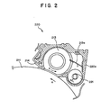
- FIG. 2 schematically shows a construction of the cleaning section 220.
- the cleaning section 220 includes a fixed pressure blade 214, a cleaning brush 213 and a waste toner screw 221.
- the fixed pressure blade 214 is in contact at a predetermined angle with the surface of the photosensitive drum 211 over the entire range in an axial direction of the photosensitive drum 211.
- the photosensitive drum 211 rotates in one direction (the direction indicated by an arrow mark a in FIGS. 1 and 2) while it is in contact with the fixed pressure blade 214, the contacting portion of the fixed pressure blade 214 exfoliates remaining toner powder sticking to the surface of the photosensitive drum 211 from the surface of the photosensitive drum 211.
- the cleaning brush 213 is disposed on the upstream side of the fixed pressure blade 214 (on the right side in FIG. 2) along the surface of the photosensitive drum 211 and extends over the entire range in a widthwise direction of the photosensitive drum 211 such that it contacts with the surface of the photosensitive drum 211.
- the cleaning brush 213 is rotated in a direction opposing to the rotation of the photosensitive drum 211 in the direction of the arrow mark a, that is, rotated in the direction indicated by another arrow mark b in FIG. 2 while it is in contact with the surface of the photosensitive drum 211 so that it conveys the remaining toner powder exfoliated from the surface of the photosensitive drum 211 by the fixed pressure blade 214 to the waste toner screw 221.
- a scraping off plate 213a is provided fixedly and extends over the entire range in an axial direction of the photosensitive drum 211 in such a manner that it sticks or extends into the cleaning brush 213.
- the waste toner screw 221 is disposed in parallel to the photosensitive drum 211.
- the waste toner screw 221 is driven to rotate in a predetermined direction (direction of an arrow mark c in FIG. 2) by a drive motor (screw driving source) not shown.
- a toner cartridge (217) used already is disposed as a waste toner collector (not shown) so that waste toner powder transported by rotation of the waste toner screw 221 in the direction of the arrow mark c drops into and is collected by the waste toner collector.
- remaining toner powder on the surface of the photosensitive drum 211 is conveyed by the cleaning brush 213 after it is exfoliated from the surface of the photosensitive drum 211 by the fixed pressure blade 214.
- the waste toner powder conveyed by the cleaning brush 213 is scraped off by the scraping off plate 213a and drops onto the waste toner screw 221.
- the waste toner powder is conveyed by the waste toner screw 221 being rotated and drops at the end of the waste toner screw 221 so that it is collected into the waste toner collector disposed below the end of the waste toner screw 221.
- a plurality of (two in the present embodiment) prechargers 215 are disposed at a position on the downstream side of the cleaning section 220 along the outer periphery of the photosensitive drum 211.
- the surface of the photosensitive drum 211 is charged uniformly by the prechargers 215.
- the exposure LED 216 is disposed at a position on the downstream side of the prechargers 215 along the outer periphery of the waste toner screw 221.
- the exposure LED 216 is formed from an LED head or a like member and serves as an exposure optical unit which irradiates an optical image corresponding to an image to be printed upon the surface of the photosensitive drum 211 to form an electrostatic latent image.
- the developing unit 219 with a toner hopper is disposed which develops an electrostatic latent image formed by the exposure LED 216 to form a toner image.
- a toner hopper 218 for supplying developing toner powder is attached to the developing unit 219 with a toner hopper, and a toner cartridge 217 which contains developing toner powder therein is removably attached to the toner hopper 218.
- the developing unit 219 with a toner hopper includes a developer counter not shown which counts up each time printing is performed.
- the photosensitive drum 211 contacts with the medium 1 at a position on the downstream side of the developing unit 219 with a toner hopper along the outer periphery of the photosensitive drum 211, and at the contacting position, a transfer station 212 including a transfer charger 212a and a separation charger 212b is disposed in an opposing relationship to the photosensitive drum 211 with the medium 1 interposed therebetween.
- the transfer charger 212a generates, at the contacting position between the photosensitive drum 211 and the medium 1, corona discharge with a potential of the opposite polarity to that of a potential of the charge of the toner image from the rear side of the medium 1 to charge the medium 1 so that a toner image may be attracted and transferred to the medium 1.
- the separation charger 212b for removing the charge of the medium 1 to facilitate separation of the medium 1 from the photosensitive drum 211 is disposed.
- the photosensitive drum 211 from which a toner image formed on the surface thereof has been transferred to the rear surface of the medium 1 is acted upon by the cleaning section 220 so that remaining toner power on the surface thereof is removed again.
- the second transfer process unit 260 is disposed for contacting with the front surface of the medium 1 above the first transfer process unit 250 and forms a toner image on the front surface of the medium 1.
- the second transfer process unit 260 has a construction common to that of the first transfer process unit 250 and is disposed in such a posture that the second transfer process unit 260 and the first transfer process unit 250 are symmetrical with respect to a vertical plane with the medium 1 interposed therebetween.
- Both of the first fixing station 410 and the second fixing station 420 fix toner images formed on the medium 1 with flash and each includes flash lamps 412 which may be xenon lamps or the like, a reflecting mirror 411 and an opposing reflecting plate 413.
- the first fixing station 410 and the second fixing station 420 have a common construction to each other.
- the flash lamps 412 are disposed on the side to which a non-fixed toner image on the medium 1 is to be fixed, and the reflecting mirror 411 is disposed at a location at which the medium 1 is not present around the flash lamps 412 so as to reflect flash light emitted from the flash lamps 412 to the fixing side surface of the medium 1.
- the opposing reflecting plate 413 is disposed at a location opposite to the flash lamps 412 and the reflecting mirror 411 with respect to the medium 1 and irradiates flash light emitted from the flash lamps 412 efficiently upon the medium 1.
- the first fixing station 410 and the second fixing station 420 are disposed at positions different from each other along the transport path of the medium 1, and in the present embodiment, the second fixing station 420 is disposed on the downstream side of the first fixing station 410.
- the first fixing station 410 fixes a toner image formed on the rear surface of the medium 1 by means of the first transfer process unit 250
- the second fixing station 420 fixes a toner image formed on the front surface of the medium 1 by means of the second transfer process unit 260.
- the first fixing station 410 and the second fixing station 420 are surrounded by ducts 83.
- the ducts 83 are communicated with the blower 8 and collects smoke, odor and so forth composed of high molecular organic substances such as styrene, butadiene and phenol generated from the first fixing station 410 and the second fixing station 420.
- the blower 8 includes a fan 81 and a filter 82 containing activated carbon or the like. Air in the ducts 83 is discharged by the fan 81 of the blower 8, and thereupon, the air which contains smoke and so forth is collected by the ducts 83 and is passed through the filter 82. The filter 82 attracts and removes the smoke, odor and so forth contained in the air. Consequently, clean air is discharged to the outside of the apparatus.
- the flash fixing unit power supply 9 supplies power to the flash lamps 412 of the first fixing station 410 and the second fixing station 420.
- a main power supply is provided in a first housing 1001 and supplies power to the first transfer process unit 250, the second transfer process unit 260, the transport system 700 and other required components.
- the control apparatus compares count values sent thereto from the developing units 219 with a toner hopper of the first transfer process unit 250 and the second transfer process unit 260 with a predetermined value recorded in advance and controls, when the count values exceed the predetermined value, so that a display member not shown may report to an operator that the filter 82 should be replaced, for example, by lighting an alarm lamp (not shown). Further, when replacement of the filter 82 is performed by the operator or some other person, the control apparatus resets the count values of the developer counters to zero.
- the transport system 700 transports the medium 1 to successively pass the first transfer process unit 250, second transfer process unit 260, first fixing station 410 and second fixing station 420 in a section from the paper hopper 10 to the stacker 60 and includes a transport tractor 710, a guide section 75, guide rollers 76, a transfer guide roller 77, a first turn-around roller pair 40 and a second turn-around roller 51.
- the transport tractor 710 is a transport apparatus for transporting the medium 1 and includes a plurality of (two in the present embodiment) tractor mechanisms 72 and 73.
- the tractor mechanisms 72 and 73 have a common construction to each other and both include an endless tractor belt 721 which has feed pins provided in a projecting manner at equal distances thereon and extends between and around a driving shaft 722 and a driven shaft 723 arranged in parallel to each other.
- a driving belt 725 extends between and around the driving shaft 722 of the tractor mechanism 72 and the driving shaft 722 of the tractor mechanism 73, and a drive motor 724 is connected to the driving shaft 722 of the tractor mechanism 72.
- the drive motor 724 is adapted to drive the driving shaft 722 to rotate at an arbitrary speed in an arbitrary direction.
- the driving shaft 722 of the tractor mechanism 72 and the driving shaft 722 of the tractor mechanism 73 are driven to rotate in synchronism with each other in the same direction to transport the medium 1 in any of a transporting direction for printing and a direction opposite to the transporting direction.
- the transport tractor 710 can transport the medium 1 at a speed higher than the transporting speed for printing.
- the transport tractor 710 includes a back tension roller 71 provided between the tractor mechanism 73 and the tractor mechanism 72, that is, on the upstream side of the tractor mechanism 72 disposed on the most downstream side, and serving as a medium tensioning member for exerting a tension in the direction opposite to the transporting direction for printing of the medium 1.
- the back tension roller 71 includes a pair of tensioning rollers including a driving side tensioning roller 712 and a driven side tensioning roller 711.
- a drive motor 714 (roller driving source) is connected to the driving side tensioning roller 712 through a one-way clutch 713 so that the driving side tensioning roller 712 is driven to rotate at an arbitrary speed in the transporting direction for printing of the medium 1 or the direction opposite to the transporting direction by the drive motor 714.
- the drive motor 714 drives the driving side tensioning roller 712 to rotate so that the circumferential speed of the driving side tensioning roller 712 in the transporting direction for printing of the medium 1 may be lower than the transporting speed for printing of the medium 1.
- the transporting speed for printing of the medium 1 must be equal to the transporting speeds of the tractor mechanisms 72 and 73, and to this end, the feed pins of tractor mechanisms 72 and 73 may always contact with leading side portions of the feed holes of the medium 1 in the transporting direction for printing. Consequently, no play appears between the feed holes of the medium 1 and the feed pins of the tractor mechanisms 72 and 73, and the transporting speed for printing of the medium 1 can be made equal to the transportation speeds of the tractor mechanisms 72 and 73 and can be stabilized.
- the circumferential speed of the driving side tensioning roller 712 is set lower so that the speed difference V1 between the circumferential speed of the driving side tensioning roller 712 and the transporting speed for printing of the medium 1 may satisfy 0 ⁇ V1 ⁇ 10 (%).
- the speed difference V1 is set to such a range as just mentioned, the medium 1 can be transported well. It is to be noted that, if the speed difference V1 is set higher than 10 %, then the feed holes of the medium 1 are damaged or broken.
- the drive motor 714 drives, when the medium 1 is to be transported in the direction opposite to the transporting direction for printing, the driving side tensioning roller 712 to rotate so that the circumferential speed of the driving side tensioning roller 712 may be higher than the transporting speed for printing of the medium 1 in the direction opposite to the transporting direction for printing of the medium 1.
- the feed pins of the tractor mechanisms 72 and 73 always contact with leading portions of the feed holes of the medium 1 in the transporting direction for printing, when the medium 1 is to be transported in the transporting direction for printing after completion of transportation of the medium 1 in the direction opposite to the transporting direction for printing, the feed holes of the medium 1 and the feed pins of the tractor mechanisms 72 and 73 are not displaced from each other and, even after transportation of the medium 1 in the direction opposite to the transporting direction for printing, the medium 1 can be transmitted immediately and stably.
- the circumferential speed of the driving side tensioning roller 712 is set higher so that the speed difference V1 between the circumferential speed of the driving side tensioning roller 712 and the transporting speed for printing of the medium 1 may satisfy 0 ⁇ V1 ⁇ 10 (%).
- the speed difference V1 is set to such a range as just mentioned, the medium 1 can be transported well. It is to be noted that, if the speed difference V1 is set higher than 10 %, then the feed holes of the medium 1 are damaged or broken.
- the driven side tensioning roller 711 presses the medium 1 against the driving side tensioning roller 712 from above the medium 1 and is driven to rotate by the medium 1 being transported.
- the driving side tensioning roller 712 when the driving side tensioning roller 712 is driven to rotate in the direction opposite to the transporting direction for printing of the medium 1 by the drive motor 714 in a condition wherein the medium 1 is held by and between the driving side tensioning roller 712 and the driven side tensioning roller 711 of the back tension roller 71, the back tension roller 71 exerts a tension in the direction opposite to the transporting direction for printing to the medium 1.
- the one-way clutch 713 is interposed between the driving side tensioning roller 712 and the drive motor 714 so that an excessive force may not be applied to the drive motor 714 even if, for example, when the medium 1 is transported at a high speed in the transporting direction for printing in order to perform replacement of the medium 1 or in a like case, the driving side tensioning roller 712 is rotated compulsorily in the transporting direction for printing by a frictional force exerted between the driving side tensioning roller 712 and the medium 1 or by some other force.
- the first turn-around roller pair 40 is interposed between the second transfer process unit 260 and the first fixing station 410 and includes a pair of first turn-around rollers 41 and 42 which are located in an opposing relationship to each other with the medium 1 interposed therebetween and contact with and are driven to rotate by the medium 1 when the medium 1 is transported.
- the first turn-around roller 41 is mounted for contacting with the rear surface of the medium 1 while the first turn-around roller 42 is mounted for contacting with the front surface of the medium 1.
- first turn-around rollers 41 and 42 have a length in the widthwise direction of the medium 1 which is set longer than the photosensitive drums 211 of the length of the first transfer process unit 250 and the second transfer process unit 260 or the second fixing station 420 in the widthwise direction of the medium 1.
- Each of the first turn-around rollers 41 and 42 is formed from, for example, a member which has a low light transmittivity and has a low light reflection factor at the surface thereof, such as, for example, an aluminum roller painted in black, and its surface is treated with a fluorine contained resin such as a PFA.
- Each of the first turn-around rollers 41 and 42 is charged at the surface thereof with the same polarity as that of toner powder.
- the medium 1 is wrapped over a predetermined angle over the first turn-around roller 42 of the first turn-around rollers 41 and 42 which compose the first turn-around roller pair 40 such that the angle defined between the transport path of the medium 1 in the second transfer process unit 260 and the transport path of the medium 1 in the second fixing station 420 may be a predetermined angle ⁇ 1 (preferably ⁇ 1 ⁇ 30 degrees).
- the first turn-around roller 42 functions as a turn-around element for changing the transporting direction of the medium 1 between the second transfer process unit 260 and the first fixing station 410.
- first turn-around roller pair 40 disposed between the second transfer process unit 260 and the first fixing station 410 functions as a light intercepting member (light intercepting roller) for preventing light leaking from the first fixing station 410 and the second fixing station 420 from arriving at the first transfer process unit 250 and the second transfer process unit 260.
- the turn-around section is formed from the first turn-around roller pair 40 composed of the first turn-around rollers 41 and 42, the turn-around section can be implemented with a simple construction and allows the medium 1 to be transported without having a bad influence upon a toner image formed on the medium 1.
- first turn-around rollers 41 and 42 of the first turn-around roller pair 40 prevent light leaking from the first fixing station 410 and the second fixing station 420 from being irradiated upon the photosensitive drums 211 of the first transfer process unit 250 and the second transfer process unit 260, reduction of the lives of the photosensitive drums 211 caused by optical deterioration can be prevented and besides deterioration of the printing quality caused by a drop of the surface potentials of the photosensitive drums 211 can be prevented.
- first turn-around rollers 41 and 42 which compose the first turn-around roller pair 40 are longer than the length of the photosensitive drums 211 of the first transfer process unit 250 and the second transfer process unit 260 or the length of the second fixing station 420 in the widthwise dimension of the medium 1, they can prevent light leaking from the first fixing station 410 and the second fixing station 420 from being irradiated upon the photosensitive drum 211 of the first transfer process unit 250 or the second transfer process unit 260 through a medium non-passing location 1a (refer to FIGS. 3 and 5) of the transport path of the medium 1. Consequently, reduction of the lives of the photosensitive drums 211 by optical deterioration can be prevented and deterioration of the printing quality by a drop of the surface potentials of the photosensitive drums 211 can be prevented.
- first turn-around rollers 41 and 42 are each formed from an aluminum roller painted in black and processed by surface treatment with a fluorine contained resin such as a PFA, the transmittivity of light thereof is so low that interception of light can be achieved with certainty. Further, since each of the first turn-around rollers 41 and 42 has a low reflection factor of light at the surface thereof, irradiation of light upon the photosensitive drums 211 of the first transfer process unit 250 and the second transfer process unit 260 caused by random reflection from the surfaces of them of light leaking from the first fixing station 410 and the second fixing station 420 can be prevented.
- first turn-around rollers 41 and 42 are processed by surface treatment with a fluorine contained resin such as a PFA, they exhibit a good releasing property of toner powder. Furthermore, since the surfaces of them are charged with the same polarity as that of toner powder, toner powder is not likely to stick to them, and consequently, a toner image is not disturbed by unnecessary toner powder.
- the angle provided by the first turn-around roller pair 40 between the transport path of the medium 1 in the second transfer process unit 260 and the transport path of the medium 1 in the second fixing station 420 is set larger than the predetermined angle ⁇ 1 (preferably ⁇ 1 ⁇ 30 degrees), light leaking from the second fixing station 420 is prevented from arriving at the first transfer process unit 250 and the second transfer process unit 260.
- first turn-around roller pair 40 functions as a light intercepting member (light intercepting roller) which prevents light leaking from the first fixing station 410 and the second fixing station 420 from arriving at the first transfer process unit 250 and the second transfer process unit 260, there is no need of providing a separate light intercepting member, and the number of parts which compose the apparatus can be reduced as much.
- the second turn-around roller 51 is disposed between the first fixing station 410 and the second fixing station 420 such that it contacts with the surface (in the present embodiment, the rear surface) of the medium 1 to which a toner image is to be fixed by the first fixing station 410, and serves as a transporting direction changing roller which contacts with the medium 1 and rotates in the transporting direction of the medium 1.
- the second turn-around roller 51 is constructed such that the medium 1 is wrapped over a predetermined angle therearound and functions as a transporting direction changing section which contacts with one of the surfaces of the medium 1 to change the transporting direction of the medium 1 between the first fixing station 410 and the second fixing station 420 so that the medium 1 is sent out to the second fixing station 420.
- the second turn-around roller 51 is formed such that the length thereof in the widthwise direction of the medium 1 may be greater than the length of the photosensitive drums 211 of the first transfer process unit 250 and the length of the second transfer process unit 260 or the second fixing station 420 in the widthwise direction of the medium 1. Further, the second turn-around roller 51 is formed from a member which has a low transmittivity of light and has a low reflection factor of light at the surface thereof.
- the second turn-around roller 51 contacts with the rear surface of the medium 1
- a toner image on the rear surface of the medium 1 at the second turn-around roller 51 has already been fixed by the first fixing station 410 and is not disturbed by the contact with the second turn-around roller 51, and consequently, the printing quality of the medium 1 is not deteriorated.
- the second fixing station 420 can be disposed at a low position, and consequently, the height of the transporting path of the medium 1 can be constructed low and the apparatus can be miniaturized.
- the second turn-around roller 51 changes the transporting direction of the medium 1, light leaking through the medium non-passing location 1a in the second fixing station 420 does not arrive at the photosensitive drums 211 of the first transfer process unit 250 and the second transfer process unit 260. Further, the second turn-around roller 51 prevents light leaking from the second fixing station 420 from propagating along the front surface of the medium 1 until it arrives at the second transfer process unit 260, and thus intercepts leaking light from the entire second fixing station 420. In this manner, the second turn-around roller 51 functions as a light intercepting member (light intercepting roller).
- the second turn-around roller 51 prevents light leaking from the second fixing station 420 from being irradiated upon the photosensitive drum 211 of the second transfer process unit 260, reduction of the life of the photosensitive drum 211 caused by optical deterioration of the photosensitive drum 211 can be prevented and besides deterioration of the printing quality by a drop of the surface potential of the photosensitive drum 211 can be prevented.
- the dimension of the second turn-around roller 51 in the widthwise direction of the medium 1 is greater than the length of the photosensitive drums 211 of the first transfer process unit 250 and the second transfer process unit 260 or the length of the second fixing station 420 in the widthwise dimension of the medium 1, leaking light can be prevented from being irradiated upon the photosensitive drums 211 of the first transfer process unit 250 and the second transfer process unit 260 through the medium non-passing location 1a of the transport path of the medium 1. Consequently, reduction of the lives of the photosensitive drums 211 by optical deterioration of the photosensitive drums 211 can be prevented and besides deterioration of the printing quality by a drop of the surface potentials of the photosensitive drums 211 can be prevented.
- the second turn-around roller 51 is formed from a member which has a low transmittivity of light, interception of light can be achieved with certainty. Further, since the surface portion of the second turn-around roller 51 is formed from a member having a low reflection factor of light, arrival of light at the photosensitive drums 211 of the first transfer process unit 250 and the second transfer process unit 260 originating from light reflected at random from the surface portion of the second turn-around roller 51 can be prevented.
- the second turn-around roller 51 serves also as a light intercepting roller as a light intercepting member which intercepts light leaking from the second fixing station 420 to prevent the leaking light from arriving at the second transfer process unit 260, the number of parts which compose the apparatus can be reduced as much, and the production cost can be reduced as much.
- the angle defined between the transport path of the medium 1 in the first fixing station 410 and the transport path of the medium 1 in the second fixing station 420 is set to a predetermined angle ⁇ 2 (preferably, for example, ⁇ 2 ⁇ 10 degrees) (in the present embodiment, to approximately 90 degrees).
- a light intercepting section 43 for intercepting light leaking from the first fixing station 410 is disposed between the second transfer process unit 260 and the first fixing station 410. A construction and operation of the light intercepting section 43 will be hereinafter described.
- the guide rollers 76 are disposed at a plurality of locations along the transport path of the medium 1 in the present apparatus and cooperate with the guide section 75, which is a curved plate-like member, to guide the medium 1 so that it passes a predetermined path.
- the guide rollers 76 guide the medium 1 so as to pass between the photosensitive drum 211 and the transfer station 212 in the first transfer process unit 250 and guide the medium 1 having passed the second fixing station 420 to the stacker 60.
- the medium 1 is wrapped over predetermined angles around the guide rollers 76 so that a frictional force exerted between the front surface of the medium 1 and the surface of each of the guide rollers 76 may act as a reactive force upon the medium 1 upon transportation of the medium 1 by the transport tractor 710 so that the medium 1 may always be kept taut during transportation thereof.
- the transfer guide roller 77 is disposed on the upstream side of the transfer station 212 of the second transfer process unit 260 along the transport path of the medium 1 on the rear surface side of the medium 1 and contacts with the rear surface of the medium 1 to guide the medium 1 to the second transfer process unit 260.
- the surface of the transfer guide roller 77 is coated with a film of a fluorine contained resin or a like material.
- the film prevents abrasion of the transfer guide roller 77 by friction with the medium 1 and prevents sticking of non-fixed toner powder on the rear surface of the medium 1 to the transfer guide roller 77.
- the first turn-around rollers 41 and 42 and the transfer guide roller 77 are charged with the same polarity as that of non-fixed toner powder on the medium 1. Consequently, when each of the first turn-around rollers 41 and 42 and the transfer guide roller 77 contacts with non-fixed toner powder on the medium 1, the non-fixed toner powder on the medium 1 does not stick to the first turn-around roller 41 or 42 or the transfer guide roller 77 and does not have a bad influence on a toner image formed on the medium 1.
- a cleaning blade not shown is mounted for contacting at a predetermined angle with each of the first turn-around rollers 41 and 42 and the transfer guide roller 77.
- the cleaning blades scrape off toner powder sticking to the surfaces of the first turn-around rollers 41 and 42 and the transfer guide roller 77.
- first turn-around rollers 41 and 42 and the transfer guide roller 77 are permitted to rotate only in the respective printing transportation directions.
- each of the first turn-around rollers 41 and 42 and the transfer guide roller 77 includes a retracting apparatus not shown.
- the first turn-around rollers 41 and 42 and the transfer guide roller 77 are retracted individually from the transport path of the medium 1 by the respective retracting apparatus so that they may not contact with the surfaces of the medium 1 which is transported at a high speed.
- the transport system 700 includes a transport roller not shown provided on the downstream side of the second fixing station 420 but on the upstream side of the stacker 60.
- the transport roller transports the medium 1 in synchronism with the transport tractor 710 described hereinabove.
- the stacker 60 is a medium stacking section for stacking the medium 1 after printed and includes a swing guide 61 and a stacker section 62.
- the swing guide 61 is rocked to guide the medium 1 transported by the guide rollers 76 so that the medium 1 is successively folded along a line of perforations thereof and stacked on the stacker section 62.
- the first transfer process unit 250, second transfer process unit 260, first fixing station 410, second fixing station 420 and transport system 700 described above are disposed in the first housing 1001 while the blower 8, stacker 60 and flash fixing unit power supply 9 are disposed in a second housing 1002.
- the stacker 60 is disposed on the downstream side of the second fixing station 420 within a range of a transport path length within which data compensation is possible by the host computer which is a host apparatus which has requested printing. Since the transport path length of the medium 1 from the second fixing station 420 to the stacker 60 is short, when some trouble such as jamming of the medium 1 occurs, re-printing for a portion over which such trouble has occurred can be performed rapidly by the host computer. Consequently, the time required for a re-setting operation can be reduced and the reliability of the apparatus can be improved.
- a medium trailing end detection section 74 for detecting a trailing end of the medium 1 is mounted on the upstream side of the tractor mechanism 73.
- the medium trailing end detection section 74 is formed, for example, from an optical sensor including a light emitting element and a light receiving element and is disposed such that the medium 1 may intercept light to be transmitted from the light emitting element to the light receiving element.
- the operator will first install the medium 1 in position into the paper hopper 10 and fit the feed pins of the tractor belt 721 of the tractor mechanism 73 into the feed holes formed on the opposite side portions of the medium 1 to attach the medium 1 in position to the tractor belt 721.
- printing data are set to the present apparatus under the control of the host computer, and double-sided printing is started.
- the medium 1 is transported by the transport system 700, and in the first transfer process unit 250, the photosensitive drum 211 is driven to rotate in the direction of the arrow mark a by the driving apparatus not shown in synchronism with the transportation of the medium 1 by the transport system 700.
- the surface of the photosensitive drum 211 is charged uniformly by the prechargers 215, and the surface of the photosensitive drum 211 is exposed to an image of light from the exposure LED 216 in response to an image signal to be printed thereby to form an electrostatic latent image thereon.
- the latent image is developed by the developing unit 219 with a toner hopper to form a toner image corresponding to the printing data on the surface of the photosensitive drum 211.
- the transfer charger 212a charges the medium 1 with the polarity opposite to that of the toner power which forms the toner image so that the toner image on the photosensitive drum 211 may be attracted to the medium 1 to transfer the non-fixed toner image to the rear surface of the medium 1. After this transfer, the charge of the medium 1 is cancelled by the separation charger 212b so as to facilitate later separation of the photosensitive drum 211 and the medium 1 from each other.
- the medium 1 is transported to the second transfer process unit 260 by the transport system 700.
- the non-fixed toner powder is transferred to the front surface of the medium 1 in a similar manner as in the first transfer process unit 250.
- the medium 1 to the opposite surfaces of which the non-fixed toner images have been transferred is transported by the transport system 700 and passes the first turn-around roller pair 40 and the light intercepting section 43. Then, the toner image which has been transferred to the rear surface of the medium 1 is fixed by the first fixing station 410.
- the medium 1 is further transported by the transport system 700. Then, after the transporting direction of the medium 1 is changed by the second turn-around roller 51, now the toner image which has been transferred to the front surface of the medium 1 is fixed by the second fixing station 420.
- the medium 1 is transported by the transport system 700 under the guidance of the guide rollers 76 and is distributed, in the stacker 60, by the swing guide 61 so that it is folded back and forth alternately along the perforations. Consequently, the medium 1 is stacked in an alternately folded condition in the stacker section 62.
- the double-sided printing apparatus since the medium 1 is transported in order through the first transfer process unit 250, second transfer process unit 260, first turn-around roller pair 40 and second fixing station 420 by the transport system 700 and the second transfer process unit 260 is disposed higher than the first transfer process unit 250 while the first fixing station 410 is disposed higher than the second transfer process unit 260, the first transfer process unit 250 and the second transfer process unit 260 can be formed with a common structure. Consequently, the cost for development and the cost for production can be reduced, and the installation area required for the apparatus can be reduced.
- the second fixing station 420 is disposed on the downstream side of the first fixing station 410 and the second turn-around roller 51 is disposed between the first fixing station 410 and the second fixing station 420 such that the transport path of the medium 1 is changed by the second turn-around roller 51, the height of the transport path of the medium 1 can be made low. Consequently, the apparatus can be constructed in a reduced size and the operability of the operator can be augmented.
- the second turn-around roller 51 is disposed on the downstream side of the first transfer process unit 250 and the second transfer process unit 260 such that the direction of the transport path of the medium 1 is changed by the second turn-around roller 51, the height of the transport path of the medium 1 can be made low, and consequently, the apparatus can be constructed in a reduced size and the operability of the operator can be augmented.
- first fixing station 410 and the second fixing station 420 are surrounded by the ducts 83 individually communicated with the blower 8 so that smoke, odor and so forth composed of high molecular organic substances such as styrene, butadiene and phenol generated from the first fixing station 410 and the second fixing station 420 are collected while a developer counter not shown is provided for each of the developing units 219 with a toner hopper of the first transfer process unit 250 and the second transfer process unit 260 such that, each time the first transfer process unit 250 and the second transfer process unit 260 perform printing, the developing units 219 with a toner hopper count up the developer counters and the count values of the developer counters are compared with a predetermined value recorded in advance by the control apparatus not shown, a timing at which the filter 82 should be replaced can be discriminated readily. Consequently, the maintenance is facilitated and the operability is improved.
- the transport tractor 710 is composed of a plurality of (two in the present embodiment) tractor mechanisms 72 and 73 and the tractor mechanisms 72 and 73 are formed in a common construction to each other, the production cost of the transport tractor 710 can be reduced.
- the driving belt 725 extends between and around the driving shaft 722 of the tractor mechanism 72 and the driving shaft 722 of the tractor mechanism 73 and the drive motor 724 is connected to the driving shaft 722 of the tractor mechanism 72; the tractor mechanisms 72 and 73 can be driven in synchronism with each other with certainty. Consequently, the medium 1 can be transported stably and the reliability of the apparatus can be augmented.
- the transport tractor 710 of the transport system 700 is disposed on the upstream side of the first transfer process unit 250 and composed of the tractor mechanisms 72 and 73, when the medium 1 is mounted in position into the present apparatus, the operator need not extend its hand to the first transfer process unit 250 disposed at a rather interior position of the apparatus as viewed from the paper hopper 10 side to mount the medium 1. Consequently, the operability in mounting the medium 1 can be augmented. Further, the medium 1 can be transported with certainty and the reliability of the apparatus can be augmented.
- tractor mechanisms 72 and 73 and the drive motor 724 are constructed such that the medium 1 can be transported in any of the transporting direction for printing and the direction opposite to the transporting direction, when some trouble such as jamming of the medium 1 occurs, as a re-setting operation, the medium 1 can be transported in the direction opposite to the transporting direction for printing to resume printing from a desired position of the medium 1 in order to print the location of the medium 1 at which the trouble has occurred.
- the back tension roller 71 is composed of the driving side tensioning roller 712 and the driven side tensioning roller 711 which are a pair of tensioning rollers, the medium tensioning section can be implemented economically with a simple construction.
- the driving side tensioning roller 712 is driven to rotate by the drive motor 714 such that the circumferential speed of the driving side tensioning roller 712 may be lower than the transporting speed for printing of the medium 1 in the transporting direction for printing of the medium 1 thereby to generate a tension to the medium 1 in the opposite direction to the transporting direction for printing so that the medium 1 can always be kept taut.
- the drive motor 714 can drive the driving side tensioning roller 712 to rotate such that the circumferential speed of the driving side tensioning roller 712 may be higher than the transporting speed for printing of the medium 1 in the direction opposite to the transporting direction for printing of the medium 1 to generate a tension to the medium 1 in the transporting direction for printing to always tension the medium 1, the medium 1 is not slackened in the transport path of the medium 1. Consequently, occurrence of a trouble such as jamming can be prevented, and the reliability of the apparatus can be augmented.
- the driven side tensioning roller 711 is mounted for releasably contacting with the medium 1 and is contacted, when the medium 1 is to be transported in the transporting direction for printing, with the medium 1 whereas, when the medium 1 is to be transported in the direction opposite to the transporting direction for printing, the driven side tensioning roller 711 is brought out of contact with the medium 1, friction does not occur between the medium 1 and the driven side tensioning roller 711. Consequently, abrasion of the driven side tensioning roller 711 can be prevented.
- waste toner powder collected by the cleaning section 220 is discharged by the waste toner screw 221 which is driven to rotate by the drive motor not shown and is collected into the waste toner collector (a toner cartridge 217 after used), waste toner powder collected in the first transfer process unit 250 and the second transfer process unit 260 can be recovered readily and the operability in maintenance operation can be augmented.
- single-sided printing may be performed using the second transfer process unit 260, second fixing station 420 and transport system 700. This allows common use of parts between the double-sided printing apparatus and the single-sided printing apparatus, and the time and the cost for development/production can be reduced.
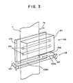
- FIG. 3 shows a construction of the light intercepting section 43 while FIG. 4 shows a construction of several components around the light intercepting section 43, and FIG. 5 is a view as viewed in the direction indicated by an arrow mark A. It is to be noted that, in FIGS. 3 to 5, some parts such as the first turn-around roller pair 40 are omitted for convenience of illustration.
- the light intercepting section 43 is disposed between the second transfer process unit 260 and the first fixing station 410 as seen from FIGS. 4 and 5, and prevents irradiation of light from the first fixing station 410 upon the photosensitive drums 211 of the first transfer process unit 250 and the second transfer process unit 260 and particularly prevents irradiation of leaking light through the medium non-passing location 1a.
- the light intercepting section 43 includes, as seen from FIG. 3, a pair of shafts 431, 431 disposed at opposing positions with the medium 1 interposed therebetween in the widthwise direction of the medium 1 and extending in parallel to each other and in a direction perpendicular to the plane in which the medium 1 is transported, and an endless belt-like member 432 extending between and around the shafts 431, 431 and having an wider portion 432a and a narrower portion 432b.
- the belt-like member 432 is formed from a member of chloroprene rubber or a like material which has a low light transmittivity and has a low light transmission factor at the surface thereof.
- the belt-like member 432 is circulated between and around the shafts 431, 431 so that light to the medium non-passing location 1a is intercepted by the wider portion 432a in accordance with the width of the medium 1.
- a cooling mechanism 433 composed of a cooling fan and so forth for sending wind to the belt-like member 432 to cool the belt-like member 432 is disposed in the proximity of the belt-like member 432. It is to be noted that the cooling mechanism 433 is omitted for convenience of illustration in FIGS. 3 and 5.
- the wider portion 432a of the belt-like member 432 is disposed at the medium non-passing location 1a in the proximity of the first fixing station 410, intense leaking light to be irradiated through the medium non-passing location 1a in the first fixing station 410 is prevented from being irradiated upon the photosensitive drums 211 of the second transfer process unit 260 and the first transfer process unit 250. Consequently, optical deterioration of the photosensitive drum 211 can be prevented, and besides, deterioration of the printing quality caused by a drop of the surface potential of each photosensitive drum 211 can be prevented.
- the light intercepting section 43 is formed from the endless belt-like member 432 having the wider portion 432a and the narrower portion 432b and extending between and around the pair of shafts 431, 431 and the belt-like member 432 is circulated around the shafts 431, 431 so that light to pass through the medium non-passing location 1a is intercepted by the wider portion 432a in accordance with the width of the medium 1, the light intercepting function can be achieved readily whatever width the medium 1 has.
- the belt-like member 432 can be produced readily by forming the wider portion 432a at a portion thereof, and the productivity can be augmented.
- the belt-like member 432 is made of chloroprene rubber or the like which has a low light transmittivity, it can intercept leaking light from the first fixing station 410 and the second fixing station 420 with certainty. Further, since chloroprene rubber further has a low light reflection factor, irradiation of light caused by random reflection light from the surface of it upon the photosensitive drum 211 can be prevented. Consequently, optical deterioration of the photosensitive drum 211 can be prevented, and also deterioration of the printing quality caused by a drop of the surface potential of each photosensitive drum 211 can be prevented.
- heating of the belt-like member 432 can be prevented also by providing the cooling mechanism 433 which cools the belt-like member 432, and thermal deterioration of the belt-like member 432 can be prevented.
- the belt-like member 432 is formed from a member (for example, of chloroprene rubber) having a low light transmittivity, it need not necessarily be formed from the specific member and can be carried out in various forms without departing from the scope of the present invention.
- the surface of the belt-like member 432 adjacent the first fixing station 410 may be formed form a member having a high light reflection factor. This augments the flash energy utilization efficiency of the first fixing station 410. Further, since heating of the belt-like member 432 can be prevented, thermal deterioration of the belt-like member 432 can be prevented.
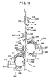
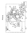
- FIGS. 6 to 8 show the paper jamming processing mechanism of the double-sided printing apparatus of the preferred embodiment of the present invention. More particularly, FIGS. 6 and 7 schematically show a construction of the paper jamming processing mechanism upon printing and upon jamming processing, respectively, and FIG. 8 is a view as viewed in the direction indicated by an arrow mark B in FIG. 7.
- each of the first transfer process unit 250 and the second transfer process unit 260 includes a developing unit 219 with a toner hopper removably mounted thereon, and each of the developing units 219 with a toner hopper is retracted away from the medium 1 when it is removed from the corresponding photosensitive drum 211.
- the developing unit 219 with a toner hopper of the first transfer process unit 250 is removable leftwardly in FIG. 1 while the developing unit 219 with a toner hopper of the second transfer process unit 260 is removable rightwardly in FIG. 1.
- the developing unit 219 with a toner hopper of the second transfer process unit 260 is operatively associated with such a paper jamming processing mechanism 300 as shown in FIGS. 6 to 8.
- the paper jamming processing mechanism 300 is a mechanism for removing the transfer station 212 of the first transfer process unit 250 from the photosensitive drum 211 in order to remove jamming of the first transfer process unit 250 with the medium 1 or the like.
- the paper jamming processing mechanism 300 includes a developing unit receiving table 301, a slide rail 302, a developing unit receiving table link 303, an operation lever 304, a pair of slide plates 305 and a transfer pivoting link 306.
- the transfer station 212 is supported for pivotal motion away from the medium 1 (in the direction indicated by an arrow mark f in FIG. 7) around a transfer station pivot shaft 305a.
- the pair of slide plates 305 are mounted on the opposite side faces of the transfer station 212, and guideways 305b are formed in the slide plates 305 substantially in parallel to the direction in which the transfer charger 212a and the separation charger 212b are juxtaposed.
- the developing unit receiving table 301 is a platform on and to which the developing unit 219 with a toner hopper is placed and fixed, and is fixed to rail members 302a of the slide rail 302.
- a pair of developing unit receiving table pins 301a are provided on the opposite side portions of the developing unit receiving table 301 adjacent the medium 1.
- the slide rail 302 extends in parallel to the developing unit receiving table 301 and holds the rail members 302a for sliding movement thereon in a horizontal direction. Accordingly, the developing unit receiving table 301 can be moved in parallel toward and away from the medium 1 (in the left and right directions in FIGS. 6 and 7) together with the developing unit 219 with a toner hopper by sliding movement of the rail members 302a on the slide rail 302.
- the developing unit receiving table link 303 is a plate-like member in which a curved guideway 303b is formed. An end portion of a developing unit receiving table pin 301a of the developing unit receiving table 301 extends through the guideway 303b. Thus, the developing unit receiving table link 303 is movable under the guidance of the guideway 303b with the developing unit receiving table pin 301a received in the guideway 303b. Further, a pivot shaft 303a extending in parallel from the photosensitive drum 211 from an end portion of the operation lever 304 extends through the developing unit receiving table link 303.
- the transfer pivoting link 306 is disposed such that it connects the guideways 305b of the slide plates 305 mounted on the opposite side faces of the transfer station 212 to the pivot shaft 303a, and a slide shaft 306a is formed at an end portion of the transfer pivoting link 306 and is fitted for sliding movement in the guideway 305b.
- the other end portion of the transfer pivoting link 306 is fitted for pivotal motion around the pivot shaft 303a.
- the operation lever 304 is fixed to an end portion of the pivot shaft 303a and extends substantially in parallel to the transfer pivoting link 306.
- the operation lever 304 is supported for pivotal motion in the direction indicated by an arrow mark d in FIG. 6 around an axis of the pivot shaft 303a.
- the transfer station 212 when jamming processing is to be performed, from a condition wherein the transfer station 212 is positioned in an opposing relationship to the photosensitive drum 211 of the first transfer process unit 250 with the medium 1 interposed therebetween and the developing unit 219 with a toner hopper is positioned adjacent the photosensitive drum 211 of the second transfer process unit 260 as seen in FIG. 6, the transfer station 212 is retracted from the photosensitive drum 211 of the first transfer process unit 250 and the developing unit 219 with a toner hopper is retracted from the photosensitive drum 211 of the second transfer process unit 260 as seen in FIG. 7.
- a process therefor is described below.
- the operation lever 304 is pivoted in the direction indicated by the arrow mark d around the axis of the pivot shaft 303a from the condition shown in FIG. 6. This pivots the transfer pivoting link 306 in the direction of the arrow mark d around the axis of the pivot shaft 303a. Thereupon, the slide shaft 306a is moved upwardly under the guidance of the guideway 305b of the slide plate 305.
- the transfer station 212 Upon the movement of the slide shaft 306a of the transfer pivoting link 306, the transfer station 212 is pivoted around the transfer station pivot shaft 305a and retracted from the photosensitive drum 211 of the first transfer process unit 250.
- the transfer pivoting link 306 is further pivoted in the direction of the arrow mark d around the axis of the slide shaft 306a until it comes to a position of a substantially vertical posture in which the pivot shaft 303a is positioned most downwardly as seen in FIG. 7.
- the developing unit receiving table link 303 is moved in the direction indicated by an arrow mark e in FIG. 7 around the slide shaft 306a.
- the developing unit receiving table pin 301a of the developing unit receiving table 301 is guided by the guideway 303b formed in the developing unit receiving table link 303 so that it moves in a direction away from the medium 1 (in the direction indicated by an arrow mark g in FIG. 7) along the slide rail 302.
- the developing unit 219 with a toner hopper is retracted from the photosensitive drum 211 of the second transfer process unit 260.
- the double-sided printing apparatus of the present embodiment which includes such a paper jamming processing mechanism 300 as described above, since the first transfer process unit 250 and the second transfer process unit 260 include the developing units 219 with a toner hopper removably mounted thereon and each of the developing units 219 with a toner hopper is moved away from the medium 1 when it is to be retracted, when paper jamming or the like occurs, a maintenance space around each of the photosensitive drums 211 can be assured. Consequently, the operation efficiency in a maintenance operation and so forth can be augmented.
- the developing unit 219 with a toner hopper of the first transfer process unit 250 is operatively associated with the paper jamming processing mechanism 300, the developing unit 219 with a toner hopper can be retracted readily from the photosensitive drum 211 of the second transfer process unit 260 simultaneously when the transfer station 212 is retracted from the photosensitive drum 211 of the first transfer process unit 250. Consequently, when paper jamming or the like occurs, a maintenance space around each of the photosensitive drums 211 can be assured, and the operation efficiency in a maintenance operation and so forth can be augmented.
- separate light intercepting members such as light intercepting rollers may be disposed on the front surface side and the rear surface side of the medium 1.
- a first light intercepting roller may be disposed adjacent the first transfer process unit 250 between the first transfer process unit 250 and the second transfer process unit 260 while a second light intercepting roller is disposed between the first fixing station 410 and the second fixing station 420.
- light leaking from the first fixing station 410 and the second fixing station 420 and intense leaking light irradiated through the medium non-passing location 1a are prevented from being irradiated upon the photosensitive drums 211 of the second transfer process unit 260 and the first transfer process unit 250. Consequently, optical deterioration of the photosensitive drums 211 can be prevented and deterioration of the printing quality caused by a drop of the surface potential of each photosensitive drum 211 can be prevented.
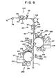
- FIGS. 9 and 10 show another double-sided printing apparatus and each shows part of a transport system of the double-sided printing apparatus. It is to be noted that, in FIGS. 9 and 10, some parts such as the first turn-around roller pair 40 and so forth described above are omitted for convenience of illustration.
- a roll-shaped light intercepting roller 44 is disposed adjacent the rear surface of the medium 1 between the first transfer process unit 250 and the second transfer process unit 260.
- the light intercepting roller 44 contacts with and is driven to rotate by the rear surface of the medium 1 when the medium 1 is transported and has a length in the widthwise direction of the medium 1 greater than the length of the photosensitive drums 211 of the first transfer process unit 250 and the second transfer process unit 260 or the length of the second fixing station 420 in the widthwise direction of the medium 1.
- the light intercepting roller 44 is formed from a member which has a low light transmittivity and has a low light reflection factor at the surface thereof, such as, for example, an aluminum roller painted in black and surface treated with a fluorine contained resin such as a PFA. Further, the light intercepting roller 44 is charged at the surface thereof with the same polarity as that of toner powder.
- a turn-around guide 512 formed from a plate-like member having a moderate convex curved surface is disposed between the first fixing station 410 and the second fixing station 420 for contacting with the rear face of the medium 1.
- the transport path of the medium 1 is set such that the angle defined by the transport path of the medium 1 in the second transfer process unit 260 and the transport path of the medium 1 in the second fixing station 420 is equal to or greater than a predetermined angle ⁇ 2 (for example, preferably ⁇ 2 ⁇ 10 degrees) (in the present embodiment, approximately 90 degrees).
- a predetermined angle ⁇ 2 for example, preferably ⁇ 2 ⁇ 10 degrees
- a light intercepting section 43 is disposed at each of a position on the upstream of the second fixing station 420 but on the downstream of the turn-around guide 512 and another position on the upstream of the first fixing station 410 but on the downstream of the second transfer process unit 260.
- the light intercepting section 43 disposed on the upstream side of the first fixing station 410 prevents irradiation of leaking light from the first fixing station 410 and intense leading light irradiated through the medium non-passing location 1a (refer to FIG. 5) and the light intercepting section 43 disposed on the upstream of the second fixing station 420 prevents irradiation of leaking light from the second fixing station 420 and intense leaking light irradiated through the medium non-passing location 1a (refer to FIG. 5) individually upon the photosensitive drums 211 of the second transfer process unit 260 and the first transfer process unit 250. Consequently, optical deterioration of the photosensitive drums 211 can be prevented, and deterioration of the printing quality caused by a drop of the surface potentials of the photosensitive drums 211 can be prevented.
- a plurality of (two in FIG. 10) second turn-around rollers 513a and 513b are disposed in place of the turn-around guide 512 of the double-sided printing apparatus shown in FIG. 9.
- a plurality of (two in FIG. 10) second turn-around rollers 513a and 513b are disposed between the first fixing station 410 and the second fixing station 420 for contacting with the medium 1.
- the second turn-around rollers 513a and 513b have a construction similar to that of the second turn-around roller 515 described hereinabove.
- the transport path of the medium 1 is set such that the angle between the transport path of the medium 1 in the second transfer process unit 260 and the transport path of the medium 1 in the second fixing station 420 is equal to or greater than a predetermined angle ⁇ 2 (for example, preferably ⁇ 2 ⁇ 10 degrees) (in the present modification, approximately 90 degrees).
- a predetermined angle ⁇ 2 for example, preferably ⁇ 2 ⁇ 10 degrees
- FIG. 11 shows another countermeasure for intercepting light leaking from fixing units in a double-sided printing apparatus and shows part of a transport system of the double-sided printing apparatus. It is to be noted that the first turn-around roller pair 40 and so forth described hereinabove are not shown for convenience of illustration.
- the first transfer process unit 250 electrophotographically transfers a toner image to the rear surface of the medium 1 under the control of the control apparatus not shown.
- the second transfer process unit 260 is disposed above the first transfer process unit 250 and has a construction similar to that of the first transfer process unit 250.
- the second transfer process unit 260 is disposed on the opposite side of the first transfer process unit 250 with respect to the medium 1 and in a symmetrical relationship with the first transfer process unit 250 with respect to a vertical plane such that it contacts with the front surface of the medium 1 to form a toner image on the front surface of the medium 1.
- the first fixing station 410 is disposed above the second transfer process unit 260 and fixes a toner image formed on the rear surface of the medium 1 by means of the first transfer process unit 250 thereof.
- the second fixing station 420 is disposed above the first fixing station 410 and fixed a toner image formed on the front surface of the medium 1 by means of the second transfer process unit 260 thereof.
- a light intercepting roller 44 which is a roller-shaped light intercepting member is disposed on the rear surface side of the medium 1 between the first transfer process unit 250 and the second transfer process unit 260.
- the light intercepting roller 44 is formed from a member which has a low light transmittivity and has a low light reflection factor at the surface thereof, such as, for example, an aluminum roller painted in black and surface treated with a fluorine contained resin such as a PFA. Further, the light intercepting roller 44 is charged at the surface thereof with the same polarity as that of toner powder.
- a cooling mechanism 453 formed from a cooling fan or the like is disposed in the proximity of the light intercepting roller 44 for sending wind to the light intercepting roller 44 to cool the light intercepting roller 44.
- a light intercepting section 43 is disposed at each of a position adjacent the first fixing station 410 with respect to the medium 1 on the downstream side of the second transfer process unit 260 but on the upstream side of the first fixing station 410 and another position adjacent the second fixing station 420 with respect to the medium 1 on the downstream side of the first fixing station 410 but on the upstream side of the second fixing station 420.
- the light intercepting sections 43 prevent light leaking from the first fixing station 410 and the second fixing station 420 from being irradiated upon the photosensitive drums 211 of the first transfer process unit 250 and the second transfer process unit 260.
- a light intercepting roller 45 which is a roller-shaped light intercepting member is disposed adjacent the front surface of the medium 1 between the first fixing station 410 and the second fixing station 420.
- the light intercepting roller 45 contacts with and is driven to rotate by the rear surface of the medium 1 when the medium 1 is transported and has a length in the widthwise direction of the medium 1 greater than the length of the photosensitive drums 211 of the first transfer process unit 250 and the second transfer process unit 260 or the length of the second fixing station 420 in the widthwise direction of the medium 1.
- the light intercepting roller 45 is formed from a member which has a low light transmittivity and has a low light reflection factor at the surface thereof, such as, for example, an aluminum roller painted in black and surface treated with a fluorine contained resin such as a PFA. Further, the light intercepting roller 45 is charged at the surface thereof with the same polarity as that of toner powder.
- the light intercepting members are formed from the light intercepting rollers 44 and 45 which are rollers, they can be implemented with a simple construction.
- the light intercepting roller 45 is disposed in the proximity of the second fixing station 420 on the downstream side of the first fixing station 410, leaking light from the second fixing station 420 can be intercepted with certainty, and consequently, the leaking light from the second fixing station 420 is not reflected irregularly in the apparatus and is not irradiated upon the photosensitive drums 211 of the first transfer process unit 250 and the second transfer process unit 260. Consequently, optical deterioration of the photosensitive drums 211 can be prevented, and deterioration of the printing quality caused by a drop of the surface potentials of the photosensitive drums 211 can be prevented.
- the second transfer process unit 260 and the first fixing station 410 are disposed at positions comparatively near to each other with the medium 1 interposed therebetween, since light leaking from the first fixing station 410 is intercepted by the medium 1, the leaking light of the first fixing station 410 is not irradiated upon the photosensitive drum 211 of the second transfer process unit 260. Consequently, optical deterioration of the photosensitive drums 211 can be prevented, and deterioration of the printing quality caused by a drop of the surface potentials of the photosensitive drums 211 can be prevented.
- the first transfer process unit 250 and the second fixing station 420 are comparatively far from each other, before light leaking from the second fixing station 420 arrives at the first transfer process unit 250, the intensity of the light becomes weak. Further, the second transfer process unit 260 and the first fixing station 410 intercept light leaking from the second fixing station 420. Consequently, optical deterioration of the photosensitive drum 211 of the first transfer process unit 250 can be prevented, and deterioration of the printing quality caused by a drop of the surface potentials of the photosensitive drum 211 can be prevented.
- the light intercepting rollers 44 and 45 have lengths in the widthwise direction of the medium 1 greater than the length of the photosensitive drums 211 of the first transfer process unit 250 and the second transfer process unit 260 or the length of the second fixing station 420 in the widthwise direction of the medium 1 and each of the light intercepting members 43 can intercept leaking light through the medium non-passing location 1a, irradiation of leading light upon the surfaces of the photosensitive drums 211 over the overall areas of them can be prevented. Consequently, optical deterioration of the photosensitive drums 211 can be prevented, and deterioration of the printing quality caused by a drop of the surface potentials of the photosensitive drums 211 can be prevented.
- each of the light intercepting rollers 44 and 45 is formed from an aluminum roller painted in black and surface treated with a fluorine contained resin such as a PFA and the belt-like member 432 (refer to FIG. 3) of each of the light intercepting members 43 is made of chloroprene rubber or the like which has a low light transmittivity, leaking light from the fixing stations can be prevented with certainty.
- the light intercepting roller 44 is cooled by the cooling mechanism 453 and the belt-like members 432 of the light intercepting members 43 are cooled by the cooling mechanisms 433, thermal deterioration of the fluorine contained resin used surface treatment of and formed on the surface of the light intercepting roller 44 can be prevented, and a high releasing performance of toner power can be maintained for a long period of time.
- the light intercepting members 43 are disposed at a position on the downstream side of the first fixing station 410 and another position on the downstream side of the second fixing station 420 such that leaking light through the medium non-passing locations 1a in the first fixing station 410 and the second fixing station 420, optical deterioration of the photosensitive drums 211 by leaking light through the medium non-passing locations 1a can be prevented, and deterioration of the printing quality caused by a drop of the surface potentials of the photosensitive drums 211 can be prevented.
- the transport tractor 710 includes the two tractor mechanisms 72 and 73 and the driving belt 725 extends between and around the driving shaft 722 of the tractor mechanism 72 and the driving shaft 722 of the tractor mechanism 73 and besides the drive motor 724 is connected to the driving shaft 722 of the tractor mechanism 72 to drive the driven shafts 723 to rotate
- the construction of the transport tractor 710 is not limited to this specific one and can be carried out in various forms without departing from the scope of the present invention.
- FIG. 12 shows a still further modification to the double-sided printing apparatus of the preferred embodiment of the present invention.
- a transport tractor 710' is composed of a pair of tractor mechanisms 72 and 73 having a common construction.
- a pair of drive motors 724', 724' independent of each other are individually connected to driving shafts 722 of the tractor mechanisms 72 and 73 and are driven in synchronism with each other by a control apparatus 726.
- the tractor mechanisms 72 and 73 can be operated in synchronism with each other and transportation of the medium 1 can be performed stably by the transport system 700.
- single-sided printing may be performed using the second transfer process unit 260, second fixing station 420, transport system 700 and so forth.
- This allows common use of parts such as the second transfer process unit 260, second fixing station 420 and transport system 700 between the double-sided printing apparatus and the single-sided printing apparatus, and thus allows reduction of the development/production costs.
- the driven side tensioning roller 711 is mounted for movement into and out of contact with the medium 1, and when the medium 1 is to be transported in the transporting direction for printing, the driven side tensioning roller 711 is contacted with the medium 1, but when the medium 1 is to be transported in the direction opposite to the transporting direction for printing, the driven side tensioning roller 711 is brought out of contact with the medium 1.
- each of the first turn-around rollers 41 and 42 and the transfer guide roller 77 includes a retracting apparatus not shown and is retracted, when the medium 1 is to be transported at a high speed, from the transport path of the medium 1, the constructions of the first turn-around rollers 41 and 42 and the transfer guide roller 77 are not limited to this specific one, and each of them may continue to always rotate in the transporting direction for printing of the medium 1 without including such a retracting apparatus as described above.
Landscapes
- Physics & Mathematics (AREA)
- General Physics & Mathematics (AREA)
- Counters In Electrophotography And Two-Sided Copying (AREA)
- Electrophotography Configuration And Component (AREA)
- Fixing For Electrophotography (AREA)
- Electrostatic Charge, Transfer And Separation In Electrography (AREA)
- Dry Development In Electrophotography (AREA)
- Cleaning In Electrography (AREA)
- Handling Of Sheets (AREA)
Claims (19)
- Dispositif d'impression recto-verso pour imprimer sur une surface recto et une surface verso d'un support continu (1), le dispositif comprenant :une première unité de traitement de formation d'image (250) pour former une image de toner sur la surface verso du support continu (1) ;une seconde unité de traitement de formation d'image (260) agencée en utilisation pour être disposée au-dessus de ladite première unité de traitement de formation d'image (250) afin de former une image de toner sur la surface recto du support continu (1) ;un premier poste de fixage (410) agencé en utilisation pour être disposé au-dessus de ladite seconde unité de traitement de formation d'image (260), ayant une lampe flash (412) qui émet un flash pour fixer l'image de toner formée sur la surface verso du support continu (1), un miroir réfléchissant (411) disposé en un emplacement dans lequel le support continu (1) n'est pas présent autour de la lampe flash afin de réfléchir le flash émis à partir de la lampe flash (412), et une plaque réfléchissante (413) disposée en un emplacement opposé à la lampe flash (412) et au miroir réfléchissant (411) par rapport au support continu (1) afin de rayonner le flash émis à partir de la lampe flash (412) ;un second poste de fixage (420) disposé du côté aval dudit premier poste de fixage (410) dans la direction de transport dudit support, ayant une lampe flash (412) qui émet un flash pour fixer l'image de toner formée sur la surface recto du support continu (1), un miroir réfléchissant (411) disposé en un emplacement dans lequel le support continu (1) n'est pas présent autour de la lampe flash afin de réfléchir le flash émis à partir de la lampe flash (412), et une plaque réfléchissante (413) disposée en un emplacement opposé à la lampe flash (412) et au miroir réfléchissant (411) par rapport au support continu (1) afin de rayonner le flash émis à partir de la lampe flash (412) ;un système de transport (700) pour transporter le support continu (1) successivement à ladite première unité de traitement de formation d'image (250), à ladite seconde unité de traitement de formation d'image (260), audit premier poste de fixage (410) et audit second poste de fixage (420) ; etune section d'empilement de supports (60) pour empiler le support continu (1) après impression ;
dans lequel ladite première unité de traitement de formation d'image (250), ladite seconde unité de traitement de formation d'image (260), ledit premier poste de fixage (410), ledit second poste de fixage (420) et ledit système de transport (700) sont disposés dans un premier logement (1001), et ledit système de transport (700) comprend :un élément de changement de direction de transport (51, 512) pour modifier une direction de transport du support continu (1) entre ledit premier poste de fixage (410) et ledit second poste de fixage (420), ledit élément de changement de direction de transport (51, 512) étant en contact avec l'une des surfaces du support continu (1) pour modifier la direction de transport du support continu (1) afin d'envoyer le support continu (1) vers ledit second poste de fixage (420) ; etun élément de rotation (42) pour modifier une direction de transport du support continu (1) entre ladite seconde unité de traitement de formation d'image (260) et ladite première section de fixage (410), ledit élément de rotation (42) étant configuré pour servir de section d'interception de la lumière afin d'intercepter la lumière s'échappant desdits premier et second postes de fixage (410, 420) de telle sorte que la lumière qui s'échappe soit empêchée d'atteindre lesdites première et seconde unités de traitement de formation d'image (250, 260). - Dispositif selon la revendication 1, dans lequel ledit élément de rotation (42) comprend un cylindre de rotation (42) qui est configuré pour, en utilisation, entrer en contact avec le support (1) et tourner dans la direction de transport du support (1), de telle sorte que
le support (1) soit enroulé selon un angle prédéterminé autour dudit cylindre de rotation (42). - Dispositif selon la revendication 1 ou 2, dans lequel ladite première unité de traitement de formation d'image (250) et ladite seconde unité de traitement de formation d'image (260) sont composées de pièces similaires les unes aux autres.
- Dispositif selon l'une quelconque des revendications 1 à 3, dans lequel ledit premier poste de fixage (410) et ledit second poste de fixage (420) sont composés de composants similaires les uns aux autres.
- Dispositif selon l'une quelconque des revendications 1 à 4, dans lequel
ledit élément de changement de direction de transport (51, 512) comprend un cylindre de changement de direction de transport (51) qui est configuré pour, en utilisation, entrer en contact avec l'une des surfaces du support continu (1) et tourner dans la direction de transport du support continu (1), de telle sorte que
le support continu (1) soit enroulé selon un angle prédéterminé autour dudit cylindre de changement de direction de transport (51). - Dispositif selon l'une quelconque des revendications 1 à 5, dans lequel ledit élément de changement de direction de transport (51, 512) est configuré pour, en utilisation, entrer en contact avec la surface verso du support continu (1) et non pas avec la surface recto du support continu (1) afin de modifier la direction de transport du support continu (1).
- Dispositif selon l'une quelconque des revendications précédentes, dans lequel ledit système de transport (700) comprend une pluralité de mécanismes de traction (72, 73) similaires les uns aux autres disposés du côté amont de ladite première unité de traitement de formation d'image (250) pour transporter le support continu (1).
- Dispositif selon la revendication 7, dans lequel ladite pluralité de mécanismes de traction (72, 73) est capable de transporter le support continu (1) soit dans une direction de transport pour imprimer soit dans une direction opposée à la direction d'impression.
- Dispositif selon la revendication 8, dans lequel ladite pluralité de mécanismes de traction (72, 73) est adaptée pour transporter le support continu (1) dans la direction opposée, de telle sorte que le support continu (1) soit transporté à une vitesse supérieure à une vitesse de transport pour imprimer.
- Dispositif selon l'une quelconque des revendications 7 à 9, comprenant en outre un élément de tension de support (71) ménagé du côté amont d'un mécanisme (72) parmi ladite pluralité de mécanismes de traction (72, 73) qui est disposé du côté le plus aval afin d'exercer une tension pour agir sur le support continu (1) dans la direction opposée à la direction de transport pour l'impression du support continu (1).
- Dispositif selon la revendication 10, dans lequel
ledit élément de tension de support (71) comprend au moins une paire de cylindres tendeurs (711, 712) disposés en relation opposée l'un par rapport à l'autre pour recevoir le support continu (1) entre eux, et
ledit dispositif d'impression recto-verso comprend en outre une source d'entraínement de cylindres (714) pour entraíner le cylindre tendeur du côté menant (712), qui est un cylindre de ladite paire de cylindres tendeurs (711, 712), à tourner tandis que le cylindre tendeur du côté mené (711) qui est l'autre cylindre de ladite paire de cylindres tendeurs (711, 712) est entraíné par le support continu (1) qui est transporté. - Dispositif selon l'une quelconque des revendications précédentes, dans lequel
chacune de ladite première unité de traitement de formation d'image (250) et de ladite seconde unité de traitement de formation d'image (260) comprend une unité de développement (219) montée de manière amovible dessus, et
lorsque ladite unité de développement (219) doit être montée ou démontée, l'unité de développement (219) de ladite unité de traitement de formation d'image (250) et l'unité de développement (219) de ladite seconde unité de traitement de formation d'image (260) sont mobiles dans des directions différentes l'une de l'autre. - Dispositif selon la revendication 12, dans lequel, lorsque l'une quelconque des unités de développement (219) doit être montée ou démontée, l'unité de développement (219) est mobile en association avec un mécanisme de traitement de bourrage de papier (300).
- Dispositif d'impression recto-verso selon l'une quelconque des revendications précédentes, dans lequel une impression recto peut être effectuée de manière sélective en utilisant ladite seconde unité de traitement de formation d'image (260), ledit second poste de fixage (420) et le système de transport (700).
- Dispositif selon l'une quelconque des revendications précédentes, dans lequel un élément d'interception de la lumière (43, 44, 45) pour intercepter la lumière s'échappant d'au moins un dudit premier poste de fixage (410) et dudit second poste de fixage (420) afin d'empêcher la lumière qui s'échappe d'arriver à ladite première unité de traitement de formation d'image (250) et à ladite seconde unité de traitement de formation d'image (260) est disposé en un emplacement de non-transmission de support (1a) à proximité d'au moins un dudit premier poste de fixage (410) et dudit second poste de fixage (420) .
- Dispositif selon l'une quelconque des revendications précédentes, dans lequel
un élément d'interception de la lumière (43, 44, 45) ayant une longueur supérieure à une longueur d'un tambour photosensible (211) de ladite première unité de traitement de formation d'image (250) ou dudit premier poste de fixage (410) dans le sens de la largeur du support continu (1) pour intercepter la lumière qui s'échappe dudit premier poste de fixage (410) afin d'empêcher la lumière qui s'échappe d'arriver à ladite première unité de traitement de formation d'image (250) est disposé entre ladite première unité de traitement de formation d'image (250) et ledit premier poste de fixage (410), et
un autre élément d'interception de la lumière (43, 44, 45) ayant une longueur supérieure à une longueur d'un tambour photosensible (211) de ladite seconde unité de traitement de formation d'image (260) ou dudit second poste de fixage (420) dans le sens de la largeur du support continu (1) pour intercepter la lumière qui s'échappe dudit second poste de fixage (420) afin d'empêcher la lumière qui s'échappe d'arriver à ladite seconde unité de traitement de formation d'image (260) est disposé entre ladite seconde unité de traitement de formation d'image (260) et ledit second poste de fixage (420, 410). - Dispositif selon la revendication 15 ou 16, dans lequel ledit premier élément d'interception de la lumière ou chacun desdits éléments d'interception de la lumière (44, 45) comprend un cylindre d'interception de la lumière (44, 45) qui est capable d'entrer en contact avec et d'être mis en rotation par le support continu (1) lorsque le support continu (1) est transporté.
- Dispositif selon la revendication 15 ou 16, comprenant en outre :une paire d'éléments formant arbre (431) disposés dans des positions opposées l'une à l'autre avec le support continu (1) intercalé entre eux dans le sens de la largeur du support continu (1) et s'étendant parallèlement l'un à l'autre dans une direction perpendiculaire à un plan dans lequel le support continu (1) est transporté ; etun élément en forme de courroie (432) s'étendant de manière sans fin entre et autour de ladite paire d'éléments formant arbre (431) et servant d'élément d'interception de la lumière (43) ;
dans lequel ledit élément en forme de courroie (432) présente une partie plus étroite (432b) capable de permettre le passage du support continu (1) et une partie plus large (432a) capable d'intercepter la lumière s'échappant du poste de fixage (410, 420) ; etledit élément en forme de courroie (432) est mis en circulation autour de ladite paire d'éléments formant arbre (431) de façon à ce que la lumière devant traverser l'emplacement de non-transmission de support (1a) soit interceptée par ladite partie plus large (432a) dudit élément en forme de courroie (432) conformément à la largeur du support continu (1). - Dispositif selon l'une quelconque des revendications précédentes, dans lequel ledit élément de changement de direction de transport (51) sert aussi d'élément d'interception de la lumière qui intercepte la lumière s'échappant dudit second poste de fixage (420) pour empêcher la lumière qui s'échappe d'arriver à ladite seconde unité de traitement de formation d'image (260).
Applications Claiming Priority (2)
| Application Number | Priority Date | Filing Date | Title |
|---|---|---|---|
| JP10306059A JP2000131893A (ja) | 1998-10-27 | 1998-10-27 | 両面印刷装置 |
| JP30605998 | 1998-10-27 |
Publications (3)
| Publication Number | Publication Date |
|---|---|
| EP0997796A2 EP0997796A2 (fr) | 2000-05-03 |
| EP0997796A3 EP0997796A3 (fr) | 2001-07-18 |
| EP0997796B1 true EP0997796B1 (fr) | 2003-10-08 |
Family
ID=17952562
Family Applications (1)
| Application Number | Title | Priority Date | Filing Date |
|---|---|---|---|
| EP99305423A Expired - Lifetime EP0997796B1 (fr) | 1998-10-27 | 1999-07-08 | Appareil d'impression double face |
Country Status (5)
| Country | Link |
|---|---|
| US (1) | US6175715B1 (fr) |
| EP (1) | EP0997796B1 (fr) |
| JP (1) | JP2000131893A (fr) |
| CN (1) | CN1113757C (fr) |
| DE (1) | DE69911882T2 (fr) |
Families Citing this family (28)
| Publication number | Priority date | Publication date | Assignee | Title |
|---|---|---|---|---|
| JP4156759B2 (ja) * | 1999-10-20 | 2008-09-24 | 富士ゼロックス株式会社 | 画像形成用トナー、2成分現像剤、画像形成方法及び画像形成用トナーの製造方法 |
| WO2003017007A1 (fr) * | 2001-08-09 | 2003-02-27 | Fuji Xerox Co., Ltd. | Imprimante |
| US7099029B2 (en) * | 2001-09-14 | 2006-08-29 | International Business Machines Corporation | Method for aligning two or more independent printing systems with a single control unit and intelligent print controllers |
| JP2003155152A (ja) * | 2001-11-20 | 2003-05-27 | Fujitsu Ltd | 画像形成装置 |
| JP2003345156A (ja) | 2002-03-19 | 2003-12-03 | Fuji Xerox Co Ltd | 画像形成装置 |
| US6975830B2 (en) | 2002-09-12 | 2005-12-13 | Ricoh Company, Limited | Image forming apparatus, process cartridge, and waste toner recovery device |
| JP4280520B2 (ja) * | 2003-03-07 | 2009-06-17 | キヤノン株式会社 | 画像形成装置 |
| US6733110B1 (en) | 2003-03-10 | 2004-05-11 | Hewlett-Packard Development Company, L.P. | Printing mechanism |
| JP2005170620A (ja) * | 2003-12-12 | 2005-06-30 | Pentax Corp | 連続紙用プリンタの用紙搬送機構、及び連続紙用プリンタ |
| CN101221401B (zh) * | 2005-01-14 | 2010-08-11 | 佳能株式会社 | 打印装置和打印控制方法 |
| JP4684792B2 (ja) * | 2005-08-01 | 2011-05-18 | キヤノン株式会社 | 定着装置及び画像形成装置 |
| JP4696898B2 (ja) * | 2005-12-22 | 2011-06-08 | 富士ゼロックス株式会社 | 連続紙印刷装置および印刷方法 |
| JP2007168396A (ja) * | 2005-12-26 | 2007-07-05 | Fuji Xerox Co Ltd | 画像形成装置 |
| US8100523B2 (en) * | 2006-12-19 | 2012-01-24 | Xerox Corporation | Bidirectional media sheet transport apparatus |
| JP2008170541A (ja) * | 2007-01-09 | 2008-07-24 | Fuji Xerox Co Ltd | 定着装置、後処理装置および画像形成装置 |
| KR101356649B1 (ko) * | 2007-07-24 | 2014-02-03 | 삼성전자주식회사 | 화상독취장치 및 이를 구비하는 화상형성장치 |
| JP5183351B2 (ja) * | 2008-08-06 | 2013-04-17 | キヤノン株式会社 | 画像形成装置 |
| CN101941334B (zh) * | 2009-07-06 | 2013-10-16 | 梁健 | 一种倍速同步单双面数码喷绘机 |
| JP2012088372A (ja) * | 2010-10-15 | 2012-05-10 | Fuji Xerox Co Ltd | 定着装置及びこれを用いた画像形成装置 |
| JP5686013B2 (ja) * | 2011-03-24 | 2015-03-18 | 富士ゼロックス株式会社 | 定着装置及びこれを用いた画像形成装置 |
| JP2012237835A (ja) * | 2011-05-11 | 2012-12-06 | Canon Inc | 画像形成システム |
| JP2013156365A (ja) * | 2012-01-27 | 2013-08-15 | Fuji Xerox Co Ltd | 画像形成装置および案内装置 |
| JP5858182B1 (ja) * | 2015-01-28 | 2016-02-10 | 富士ゼロックス株式会社 | 冷却装置、画像形成装置 |
| CN111907220B (zh) * | 2016-01-08 | 2022-09-20 | 恩图鲁斯特咨询卡有限公司 | 具有卡片返回路径的卡片印刷机构 |
| CN106042660B (zh) * | 2016-06-12 | 2017-11-28 | 联想(北京)有限公司 | 一种打印组件、打印机及打印系统 |
| US10933658B2 (en) | 2016-09-12 | 2021-03-02 | Hewlett-Packard Development Company, L.P. | Bar clamp for media |
| CN113427908B (zh) * | 2021-08-04 | 2024-08-23 | 四川金晶绘科技有限责任公司 | 一种uv打印机及其打印方法 |
| CN118849644A (zh) * | 2024-08-13 | 2024-10-29 | 山东海邦达机电科技有限公司 | 一种短距双面打印装置及打印方法 |
Family Cites Families (22)
| Publication number | Priority date | Publication date | Assignee | Title |
|---|---|---|---|---|
| JPS5688161A (en) | 1979-12-20 | 1981-07-17 | Ricoh Co Ltd | Flash fixing device of electrophotographic copier |
| JPS58173774A (ja) | 1982-04-05 | 1983-10-12 | Nec Corp | フラツシユ定着装置 |
| DE3406244A1 (de) | 1984-02-21 | 1985-08-22 | Siemens AG, 1000 Berlin und 8000 München | Laserdrucksystem fuer mehrfarben- und rueckseitendruck |
| JPS60232581A (ja) * | 1984-05-04 | 1985-11-19 | Dainippon Screen Mfg Co Ltd | 定着装置 |
| JPS6120075A (ja) | 1984-07-09 | 1986-01-28 | Fuji Xerox Co Ltd | フラツシユ定着装置 |
| EP0517700B1 (fr) * | 1990-02-26 | 1994-07-13 | Siemens Nixdorf Informationssysteme Aktiengesellschaft | Dispositif d'impression electrophotographique modulaire |
| DE4129277A1 (de) * | 1991-09-03 | 1993-03-04 | Siemens Nixdorf Inf Syst | Elektrofotografisches simultan-doppeldrucksystem |
| JP3121930B2 (ja) | 1992-09-10 | 2001-01-09 | 富士通株式会社 | 画像記録装置 |
| US5455668A (en) | 1993-06-18 | 1995-10-03 | Xeikon Nv | Electrostatographic single-pass multiple-station printer for forming an image on a web |
| EP0677792B1 (fr) | 1994-04-05 | 2002-08-28 | Xeikon Nv | Appareil de copie ou d'impression électrostatographique |
| US5461470A (en) | 1993-06-18 | 1995-10-24 | Xeikon Nv | Electrostatographic single-pass multiple station printer for forming images on a web |
| JPH07237336A (ja) | 1994-01-10 | 1995-09-12 | Fujitsu Ltd | 連続紙の両面印刷システム |
| US5614996A (en) * | 1994-03-03 | 1997-03-25 | Kyocera Corporation | Toner storage unit, residual toner collect unit, toner container with these units and image forming apparatus with such toner container |
| TW307822B (fr) | 1994-03-11 | 1997-06-11 | Xeikon Nv | |
| EP0784810B1 (fr) * | 1994-10-06 | 1999-08-04 | Océ Printing Systems GmbH | Dispositif de renversement a insertion manuelle pour support d'impression en forme de bande |
| JPH08248695A (ja) * | 1995-03-07 | 1996-09-27 | Konica Corp | 両面プリント装置 |
| US5765081A (en) * | 1995-05-09 | 1998-06-09 | Agfa-Gevaert | Electrostatographic multi-color printer for duplex printing on a web-type toner receptor material |
| JPH106583A (ja) | 1996-06-21 | 1998-01-13 | Hitachi Koki Co Ltd | プリンタの紙送り速度制御方法 |
| JPH10115954A (ja) * | 1996-10-11 | 1998-05-06 | Ricoh Co Ltd | 画像形成装置 |
| JP3361715B2 (ja) * | 1997-03-19 | 2003-01-07 | 富士通株式会社 | 画像形成装置 |
| JP3384707B2 (ja) * | 1997-03-19 | 2003-03-10 | 富士通株式会社 | 画像形成装置 |
| JPH10268664A (ja) * | 1997-03-28 | 1998-10-09 | Konica Corp | 画像形成装置 |
-
1998
- 1998-10-27 JP JP10306059A patent/JP2000131893A/ja active Pending
-
1999
- 1999-06-28 US US09/340,597 patent/US6175715B1/en not_active Expired - Lifetime
- 1999-07-08 DE DE69911882T patent/DE69911882T2/de not_active Expired - Lifetime
- 1999-07-08 EP EP99305423A patent/EP0997796B1/fr not_active Expired - Lifetime
- 1999-07-29 CN CN99110268A patent/CN1113757C/zh not_active Expired - Fee Related
Also Published As
| Publication number | Publication date |
|---|---|
| CN1252356A (zh) | 2000-05-10 |
| JP2000131893A (ja) | 2000-05-12 |
| DE69911882T2 (de) | 2004-05-19 |
| DE69911882D1 (de) | 2003-11-13 |
| US6175715B1 (en) | 2001-01-16 |
| EP0997796A3 (fr) | 2001-07-18 |
| CN1113757C (zh) | 2003-07-09 |
| EP0997796A2 (fr) | 2000-05-03 |
Similar Documents
| Publication | Publication Date | Title |
|---|---|---|
| EP0997796B1 (fr) | Appareil d'impression double face | |
| US6118956A (en) | Duplex printing apparatus and control method of the same apparatus | |
| US8417142B2 (en) | Image forming apparatus having developing device cooling mechanism, and control method therefor | |
| JP4574720B2 (ja) | 現像装置、プロセスカートリッジ、及び電子写真画像形成装置 | |
| US8095059B2 (en) | Image forming apparatus with coating mode | |
| US6292649B1 (en) | Continuous medium printing apparatus | |
| JP2002169447A (ja) | 画像形成装置及び画像形成方法 | |
| US7391990B2 (en) | Waste developer collecting container for color image forming apparatus | |
| US8280265B2 (en) | Image forming apparatus with drive control unit | |
| EP1045295B1 (fr) | Appareil d'impression double face | |
| JP2000221847A (ja) | 画像形成装置及びこの装置を構成するユニットの交換方法 | |
| JP4694740B2 (ja) | 現像装置 | |
| JP2002333814A (ja) | 画像形成装置の排紙冷却装置 | |
| JP2003255788A (ja) | 画像形成装置 | |
| JP2001183914A (ja) | 画像形成装置 | |
| JP3874088B2 (ja) | 画像形成装置 | |
| JP7566641B2 (ja) | 画像形成装置 | |
| JP2007047432A (ja) | 画像形成装置 | |
| CN116841169A (zh) | 图像形成装置 | |
| JP2003186364A (ja) | 画像形成装置 | |
| JP4877723B2 (ja) | 画像形成装置 | |
| JP5065852B2 (ja) | 画像形成装置のクリーニング装置 | |
| JP2007147862A (ja) | 画像形成装置 | |
| JP2023072953A (ja) | 画像形成装置 | |
| JP2003050527A (ja) | 画像形成装置 |
Legal Events
| Date | Code | Title | Description |
|---|---|---|---|
| PUAI | Public reference made under article 153(3) epc to a published international application that has entered the european phase |
Free format text: ORIGINAL CODE: 0009012 |
|
| AK | Designated contracting states |
Kind code of ref document: A2 Designated state(s): DE FR GB |
|
| AX | Request for extension of the european patent |
Free format text: AL;LT;LV;MK;RO;SI |
|
| PUAL | Search report despatched |
Free format text: ORIGINAL CODE: 0009013 |
|
| AK | Designated contracting states |
Kind code of ref document: A3 Designated state(s): AT BE CH CY DE DK ES FI FR GB GR IE IT LI LU MC NL PT SE |
|
| AX | Request for extension of the european patent |
Free format text: AL;LT;LV;MK;RO;SI |
|
| 17P | Request for examination filed |
Effective date: 20010903 |
|
| 17Q | First examination report despatched |
Effective date: 20011126 |
|
| AKX | Designation fees paid |
Free format text: DE FR GB |
|
| GRAH | Despatch of communication of intention to grant a patent |
Free format text: ORIGINAL CODE: EPIDOS IGRA |
|
| GRAH | Despatch of communication of intention to grant a patent |
Free format text: ORIGINAL CODE: EPIDOS IGRA |
|
| GRAH | Despatch of communication of intention to grant a patent |
Free format text: ORIGINAL CODE: EPIDOS IGRA |
|
| RAP1 | Party data changed (applicant data changed or rights of an application transferred) |
Owner name: FUJI XEROX CO., LTD. |
|
| GRAA | (expected) grant |
Free format text: ORIGINAL CODE: 0009210 |
|
| AK | Designated contracting states |
Kind code of ref document: B1 Designated state(s): DE FR GB |
|
| REG | Reference to a national code |
Ref country code: GB Ref legal event code: FG4D |
|
| REF | Corresponds to: |
Ref document number: 69911882 Country of ref document: DE Date of ref document: 20031113 Kind code of ref document: P |
|
| ET | Fr: translation filed | ||
| PLBE | No opposition filed within time limit |
Free format text: ORIGINAL CODE: 0009261 |
|
| STAA | Information on the status of an ep patent application or granted ep patent |
Free format text: STATUS: NO OPPOSITION FILED WITHIN TIME LIMIT |
|
| 26N | No opposition filed |
Effective date: 20040709 |
|
| PGFP | Annual fee paid to national office [announced via postgrant information from national office to epo] |
Ref country code: FR Payment date: 20110727 Year of fee payment: 13 |
|
| PGFP | Annual fee paid to national office [announced via postgrant information from national office to epo] |
Ref country code: GB Payment date: 20110706 Year of fee payment: 13 Ref country code: DE Payment date: 20110615 Year of fee payment: 13 |
|
| GBPC | Gb: european patent ceased through non-payment of renewal fee |
Effective date: 20120708 |
|
| REG | Reference to a national code |
Ref country code: FR Ref legal event code: ST Effective date: 20130329 |
|
| PG25 | Lapsed in a contracting state [announced via postgrant information from national office to epo] |
Ref country code: GB Free format text: LAPSE BECAUSE OF NON-PAYMENT OF DUE FEES Effective date: 20120708 Ref country code: DE Free format text: LAPSE BECAUSE OF NON-PAYMENT OF DUE FEES Effective date: 20130201 Ref country code: FR Free format text: LAPSE BECAUSE OF NON-PAYMENT OF DUE FEES Effective date: 20120731 |
|
| REG | Reference to a national code |
Ref country code: DE Ref legal event code: R119 Ref document number: 69911882 Country of ref document: DE Effective date: 20130201 |