EP0999045A1 - Einrichtung zur Abschirmung der Oberfläche von Druckformen - Google Patents
Einrichtung zur Abschirmung der Oberfläche von Druckformen Download PDFInfo
- Publication number
- EP0999045A1 EP0999045A1 EP99120856A EP99120856A EP0999045A1 EP 0999045 A1 EP0999045 A1 EP 0999045A1 EP 99120856 A EP99120856 A EP 99120856A EP 99120856 A EP99120856 A EP 99120856A EP 0999045 A1 EP0999045 A1 EP 0999045A1
- Authority
- EP
- European Patent Office
- Prior art keywords
- printing form
- printing
- shield
- area
- cylinder
- Prior art date
- Legal status (The legal status is an assumption and is not a legal conclusion. Google has not performed a legal analysis and makes no representation as to the accuracy of the status listed.)
- Granted
Links
- 238000004804 winding Methods 0.000 claims description 16
- 239000000853 adhesive Substances 0.000 claims description 11
- 230000001070 adhesive effect Effects 0.000 claims description 11
- 239000011248 coating agent Substances 0.000 claims description 8
- 238000000576 coating method Methods 0.000 claims description 8
- 239000011888 foil Substances 0.000 claims description 2
- 230000001681 protective effect Effects 0.000 abstract 1
- 239000010408 film Substances 0.000 description 8
- 238000000034 method Methods 0.000 description 5
- 230000002093 peripheral effect Effects 0.000 description 4
- 230000001771 impaired effect Effects 0.000 description 1
- 238000009434 installation Methods 0.000 description 1
- 238000004519 manufacturing process Methods 0.000 description 1
- 239000002245 particle Substances 0.000 description 1
- 238000005096 rolling process Methods 0.000 description 1
- 238000006748 scratching Methods 0.000 description 1
- 230000002393 scratching effect Effects 0.000 description 1
- 238000000926 separation method Methods 0.000 description 1
- 230000001360 synchronised effect Effects 0.000 description 1
- 239000010409 thin film Substances 0.000 description 1
Images





Classifications
-
- B—PERFORMING OPERATIONS; TRANSPORTING
- B41—PRINTING; LINING MACHINES; TYPEWRITERS; STAMPS
- B41F—PRINTING MACHINES OR PRESSES
- B41F27/00—Devices for attaching printing elements or formes to supports
- B41F27/12—Devices for attaching printing elements or formes to supports for attaching flexible printing formes
Definitions
- the invention relates to a device for shielding the surfaces of Printing forms, such as those on the printing form cylinders of offset rotary printing machines be applied, be it by hand or by means of automatic printing plate changing devices.
- EP 0 678 383 B1 relates to a device for changing printing forms Rotary printing machines.
- Printing form cylinders comprise a channel that connects the two Receives ends of a printing form, the surface of the printing forms around the Printing forme cylinder is wound around, and one is still on the Printing form cylinder located printing form released by clamping devices and in a receiving device is transportable and with a device for Feeding of a new printing form to the printing form cylinder.
- An area of The printing form to be fed is temporarily fixed by swiveling holding means and deformed so elastically that one end of the new printing form for automatic Is inserted into the channel on the outer surface of the printing form cylinder.
- the printing surface of the printing form rolls directly on a large number of freely rotatable rollers, which are caused by friction in the printing plate surface Rotation. This causes a certain degree of friction between the printing surface of the printing form and the outer peripheral surfaces of the free rotatable roller. Since the printing surface of the printing form is very sensitive, can this can damage the printing form.
- EP 0 734 859 A1 relates to a device for changing printing forms.
- a swiveling printing form loading unit comprises both a printing form feed and a mold removal tray.
- the printing form loading device is both in one Working position on the channel of a printing form cylinder with clamping devices as also pivotable into a loading position in which the printing form loading unit from the Working position is withdrawn.
- the one that swivels into a vertical loading position Printing form loading unit can be pivoted onto a holding element, on which a Inlet area for a printing form and the printing form cylinder Conveying devices for a printing form to be applied to the printing form cylinder are provided.
- the solution according to the present invention has a number of advantages hand in hand.
- Printing form will damage or soiling the printing area effectively precludes the preparatory work necessary for printing. Even those left on automatic feeders or exchangers Color residues cannot cover the printing area of the printing forms affect. Scratching the printing area is now no longer to be feared, since the sensitive, pre-treated areas of the printing form are completely covered by the shield. The only one not at the moment pre-treated areas of the printing form adhering shielding is only at the Pulling the printing form away from this, so that the printing form over the remains protected against external influences for as long as possible.
- This Coating is applied to the area of the shield outside the printing area of the printing form.
- the shield may be more preferred Be designed as a film.
- the shield can also be band-shaped endless running part, it can also be the printing form completely be wrapped.
- the printing form already provided with the shield can advantageously be attached to a magazine insert for printing plate changing devices recorded and assembled become. This can damage the printing area caused by the in the Printing form changing device recorded stationary guides or through the there provided rotating guide body effective for the printing form be excluded.
- the magazine insert itself or the Printing form changing devices can be with hooking devices for the area of Be shielded, the length of the printing area to be shielded the printing form.
- the magazine insert can be used for Printing form changing device also be a driven winding shaft, which during the mounting of the printing form on the jacket of the printing form cylinder the shield is removed from the printing form and is thus ready for assembly the printing form on the circumference of the cylinder.
- the liability of Shielding on the printing form is just such that, on the one hand, an effective one Protection of the printing area is guaranteed, on the other hand the shielding is to be removed from the printing area without leaving any residue.
- the criterion of residue-free removal of the shield from the printing area of the printing form important insofar as any remaining residues color the Printing form can significantly affect what the startup of the Rotary printing presses on production speed by required Rework can significantly delay.
- the printing form according to the invention can in particular in automatic Plate changing devices are used, which the printing units of Rotary printing press are assigned, regardless of whether sheet or web processing Rotary printing machines.
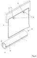
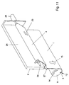
- Fig. 1 shows a printing form which is provided with an overhanging shield.
- the printing form 1 has a front edge 3 and a rear edge 2, both of which can be hung in a clamping channel 12 provided on a printing form cylinder 11 and are clamped to the circumference of the printing form cylinder 11 by means of clamping and tensioning devices provided there.
- the printing form 1 is provided with a printing area 8 which has been pretreated to such an extent that printing can be carried out after the printing form has been opened and the inking has been completed.
- the printing area is covered by a shield 4, which stops at its adhesive area 5 on the printing form 1, specifically outside the pretreated printing area 8. In the adhesive area 5, for example, a coating can be applied to the shield 4, which prevents the shield 4 from adhering on the printing form 1 enables, on the other hand, can be removed again without leaving any residue.
- the shield 4 can advantageously be designed as a thin film.
- openings 6 can be provided with which the shield 4 can be attached to a magazine insert 10.
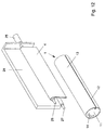
- Fig. 2 shows a printing form with a shield, the overhanging area of which is attached to a magazine insert.
- Fig. 3 shows the mounting of a printing form on a printing form cylinder and Shield removal.
- the printing form 1 is one with the front edge 3 in the clamping channel 12 Printing form cylinder 11 let in while the printing form cylinder 11 during of the winding process in the direction of rotation 14. While pulling up the Printing form 1 moves this in the drawing direction 15 to the circumference of the Printing form cylinder 11. To the extent that the printing form 1 to be mounted on the Surrounds the circumferential surface of the printing form cylinder 11, the shield 4 of of the printing form 1 and thus the printing area 8 of the printing form 1 successively exposed. So is the printing area 8 of the printing form 1 to immediate before mounting them on the circumference of the printing form cylinder 11 by the Shield 4 effectively protected. The one hung on the hook 9 The overhang area 7 of the shield 4 remains during the mounting of the printing form 1 and the gradual detachment of the shield 4 hang on the catch hook 9, the Adhesive area 5 separates from the printing area 8 without residue.
- the removal of the adhesive area 5 from the printing form 1 takes place successively during the Mount the printing form on the printing form cylinder 11.
- the adhesive force of the adhesive Areas of the shield 4 is dimensioned so that on the one hand an effective Protection of the printing area 8 against external influences, on the other hand Liability is such that the shield 4 is completely and residue-free from the Surface of the printing form 1 is removable.
- the printing form 1, the 16 in the clamped state, the peripheral surface of the Printing cylinder 11 completely surrounds is now prepared for printing.
- the shield 4 is completely removed from the peripheral surface 13, the The inking process and printing can begin.
- On magazine insert 10 is the Shield 4 attached, the previously shown in FIG. 3 when mounting the printing form 1 the printing form cylinder 11 detached from the surface of the printing area 8 has been. It hangs, picked up by the catch hooks 9, from the magazine insert 10 and can from the printing plate changing device not shown here be enclosed.
- FIGS. 5-9 show a further embodiment of the solution according to the invention described.
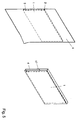
- FIG. 5 shows an example of a printing form 1 which is wrapped in a shield 4.
- the shield 4 has a front edge 3 and a rear edge 2 of the printing form 1 over surrounding areas, which stick to each other when placed on top of each other.
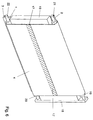
- FIG. 6 shows an endless shield running around a magazine insert.
- an insert 10 includes a longitudinal beam 18, on the upper and lower Each end of a roller 19 and 20 is rotatably received. Rollers 19 and 20 are each mounted with pins 21, 22 in the longitudinal beam 18. To the surfaces of the Rollers 19, 20 runs around the endless shield 4, which at its end region in the Connection area 17 adhered to each other. The on the endless shield 4 recorded printing form 1 lies with its printing area 8 by means of the endless Shield 4 on magazine insert 10 without touching it.
- the illustration 7 is the mounting process of the printing form 1 on the jacket of the Printing form cylinder 11 shown. The printing form 1 is with its front edge 3 in Clamping channel 12 of the printing form cylinder 11 is added and is during this slowly moved in the direction of rotation 14, mounted on the circumference of the cylinder 11.
- the mounting direction of the printing form 1 on the jacket of the printing form cylinder 11 is included Denotes reference numeral 23; while the printing forme 11 is being opened, the Endless shield 4 continuously around the rollers 19, 20 and thereby solves the printing area 8 of printing form 1 shielding area of shield 4 slowly from this.
- the connection region 17 has the Shield 4 moves upwards, so the printing form 1 is already further accrued on the circumference of the printing form cylinder 11.
- the Downward movement of the printing form according to reference numeral 23 on the peripheral surface of the Printing forme cylinder 11 out there is no relative movement between the separating Shield 4 and the surface of the printing form 1.
- the transfer movement is here directed perpendicular to the surface of the printing form 1, and requires only a small Effort. Damage to the surface of the printing form 1 by such Kind of transfer movement is almost impossible.
- the printing form 1, the printing area 8 of which is provided with a shield 4 are attached to the magazine insert 10 such that the overhanging areas around the two rollers 19 and 20 are beaten, then the ends of the Shield 4 placed on top of each other and form the connection area 17 as in the Figures 6 and 7 already shown.
- Fig. 8 is a printing form completely wound on the cylinder surface reproduced.
- the printing form 1 is now completely separated from the endless shield 4 rotates around the two rollers 19 and 20 of the insert 10.
- the shield 4 can if necessary, can be reused by the ends in the connection region 17 are separated and then a printing area of a printing form 1 is covered and can be protected against external influences. It is important that the shield 4 as soon as possible after the printing treatment necessary for printing Area 8 is applied to the respective printing area 8 of the printing form 1.
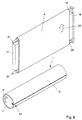
- Fig. 9 shows a printing form as already shown in Fig. 1, with one down overhanging shield.
- the printing area 8 is covered by a shield 4, which is covered with a Adhesive area 5 on the surface of the printing form 1 outside the printing area 8 attached.
- the printing form 1 has a front edge 3 and a rear edge 2.
- 10 is a printing form 1 provided with a shielding film 4 on one Magazine insert 24 of a printing plate changing device added.
- the overhang region 7 of the shielding film 4 can be driven by the operator Winding roller 26 are placed. This is driven by a drive 25 for example by means of an electric motor. After the rear end of the Shield 4 is wound around the roller 26, can be in accordance with the feed Pulling the printing form 1 onto the printing form cylinder 11, the shield 4 onto the driven winding roller 26 are added. To avoid Damage to the surface of the shield 4 is one Deflection roller 27 guided, which is provided at the lower end of the magazine 24.
- Fig. 11 shows the detachment of the shield 4 from the printing form 1, which on the Printing form cylinder 11 is applied.
- the printing forme 1 is fed in the pull-up direction 15 by rotating the Printing form cylinder 11 in the direction of rotation 14.
- the printing form 1 is thus on the in the clamping channel 12 attached printing form leading edge 3 drawn on its circumference.
- the shield 4 is continuously applied to the winding roller 26 wound up.
- the winding speed of the drive 25 is with the Winding speed of printing form 1 synchronized with printing form cylinder 11, so that there is no speed difference between the surface of the Printing form 1 and the shield 4 comes.
- the shield 4 becomes continuous detached from this according to the feed of the printing form 1 and not by a pulling off laterally, but by detaching the shielding film 4 perpendicular to the surface of the printing form 1.
- the rolling movement of the detached Shielding film 4 takes place in the direction of the arrow according to FIG. 11 on the driven one Winding roller 26.
- a wound shielding film 4 on the driven winding roller 26 there can also be several shielding foils from several different ones Winding operations originating from printing forms, which are then recorded as a whole can be removed again from the magazine insert 24 received shaft.
- the Deflection roller 27 at the bottom of the magazine insert 24 is used for gentle deflection of the Shielding film 4 on the driven winding shaft 26. Furthermore, the roller 27 serves to to influence the direction of separation so that it is perpendicular to the surface of the Printing form 1 is directed.
- Printing form cylinder 11 completely surrounds, the front and rear edge thereof in Clamping channel 12 of the printing form cylinder 11 are added.
Landscapes
- Supply, Installation And Extraction Of Printed Sheets Or Plates (AREA)
Abstract
Description
- Fig. 1
- eine Druckform, die mit einer überhängenden Abschirmung versehen ist,
- Fig. 2
- eine Druckform, deren überhängender Bereich an einem Magazineinsatz zum Einbau in einer automatische Druckformwechseleinrichtung einsetzbar ist,
- Fig. 3
- das Aufziehen der Druckform auf einen Druckformzylinder unter Entfernung der Abschirmung,
- Fig. 4
- die von der Druckform abgelöste Abschirmung,
- Fig. 5
- eine weitere Ausführungsvariante einer Abschirmung, welche die Druckform einhüllt,
- Fig. 6
- eine endlose auf einem Magazineinsatz umlaufende Abschirmung,
- Fig. 7
- den Aufziehvorgang einer Druckform auf den Mantel des Zylinder,
- Fig. 8
- eine fertig aufgezogene Druckform,
- Fig. 9
- eine weitere Ausführungsform einer Abschirmung,
- Fig. 10
- einen Magazineinsatz mit angetriebener Aufwickelwelle für die Abschirmung,
- Fig. 11
- den Aufziehvorgang unter Ablösung der Abschirmung gemäß Fig. 10, und
- Fig. 12
- die auf den Druckformzylinder aufgezogene Druckform sowie die vollständig aufgewickelte Abschirmung.
Fig. 2 zeigt eine Druckform mit einer Abschirmung, deren überhängender Bereich an einem Magazineinsatz eingehangen ist.
- 1
- Druckplatte
- 2
- Hinterkante
- 3
- Vorderkante
- 4
- Abschirmung
- 5
- Haftbereich
- 6
- Öffnung
- 7
- Überhangbereich
- 8
- druckender Bereich
- 9
- Fanghaken
- 10
- Magazineinsatz
- 11
- Druckformzylinder
- 12
- Spannkanal
- 13
- Umfangsfläche
- 14
- Rotationsachse
- 15
- Aufzugsrichtung
- 16
- aufgespannter Zustand
- 17
- Verbindungsbereich
- 18
- Träger
- 19
- Walze
- 20
- Walze
- 21
- Zapfen
- 22
- Zapfen
- 23
- Bewegungsrichtung Abschirmung
- 24
- Magazineinsatz
- 25
- Antrieb
- 26
- angetriebene Wickelwelle
- 27
- Umlenkwalze
Claims (17)
- Druckform zum Aufbringen auf einen Zylinder einer Rotationsdruckmaschine, wobei die Endbereiche der Druckform in Spanneinrichtungen an einem Zylinder aufgenommen werden und die Druckform eine für den Druck vorbereitete Oberfläche aufweist, dadurch gekennzeichnet, daß ein druckender Bereich (8) der Druckform (1) von einer abziehbaren Abschirmung (4) bedeckt ist, die beim Aufziehen der Druckform (1) auf einen Druckformzylinder (11) von der Druckform (1) entfernbar ist.
- Druckform gemäß Anspruch 1, dadurch gekennzeichnet, daß die Abschirmung (4) mit einer an der Druckform (1) anhaftenden Beschichtung versehen ist.
- Druckform gemäß Anspruch 2, dadurch gekennzeichnet, daß die Beschichtung in einem den druckenden Bereich (8) umgebenden Haftbereich (5) an der Oberfläche der Druckform (1) anhaftet.
- Druckform gemäß Anspruch 1, dadurch gekennzeichnet, daß die Abschirmung (4) eine endliche Folie ist.
- Druckform gemäß Anspruch 2, dadurch gekennzeichnet, daß die Abschirmung (4) an ihren gegenüberliegenden Enden mit einer anhaftenden Beschichtung versehen ist.
- Druckform gemäß Anspruch 5, dadurch gekennzeichnet, daß die Abschirmung (4) die Druckform (1) vollständig umgibt und zwischen den Enden einen Verbindungsbereich (17) bildet.
- Druckform gemäß Anspruch 1, dadurch gekennzeichnet, daß die Druckform (1) samt Abschirmung (4) an einem Magazineinsatz (10) für Druckformwechselsysteme aufgenommen ist.
- Druckform gemäß Anspruch 1, dadurch gekennzeichnet, daß ein Überhangbereich (7) der Abschirmung (4) am Magazineinsatz (10, 24) aufgenommen wird.
- Druckform gemäß Anspruch 8, dadurch gekennzeichnet, daß der Magazineinsatz (10) mit Einhängvorrichtungen (6) für den Überhangbereich (7) der Abschirmung (4) versehen ist.
- Druckform gemäß Anspruch 8, dadurch gekennzeichnet, daß der Magazineinsatz (24) mit einer Aufwickeleinrichtung (25, 26) für den Überhangbereich (7) der Abschirmung (4) versehen ist.
- Druckform gemäß Anspruch 1, dadurch gekennzeichnet, daß während des Aufziehens der Druckform (1) auf den Umfang des Plattenzylinders (11) die Abschirmung (4) vom druckenden Bereich (8) der Druckform (1) abgezogen wird.
- Druckform gemäß Anspruch 11, dadurch gekennzeichnet, daß sich die Abschirmung (4) während des Aufziehens der Druckform (1) in Aufzugsrichtung (15) an ihrem Haftbereich (5) von der Druckform (1) löst.
- Druckform gemäß Anspruch 11, dadurch gekennzeichnet, daß die Abschirmung (4) während des Aufziehens der Druckform (1) in Aufzugsrichtung (15) von einer am Magazineinsatz aufgenommenen Wickelwelle (26) aufgewickelt wird.
- Druckform gemäß Anspruch 5, dadurch gekennzeichnet, daß eine an ihren Enden einen Verbindungsbereich (17) bildende Abschirmung (14) von einem Magazinein-satz (10) aufgenommen ist und die Druckform (1) beim Aufziehen auf den Druckformzylinder (11) von dieser abgeschält wird.
- Druckform gemäß Anspruch 14, dadurch gekennzeichnet, daß die an ihren Enden einen Verbindungsbereich (17) bildende Abschirmung (4) um Umlenkkörper (19, 20) des Magazineinsatzes (24) umläuft.
- Druckformwechseleinrichtung zum Austausch von Druckformen an einem Zylinder von Rotationsdruckmaschinen, wobei die Endbereiche der Druckform in Spann- einrichtungen des Zylinders aufgenommen werden und die Druckform eine für den Druck vorbereitete Oberfläche aufweist, dadurch gekennzeichnet, daß ein druckender Bereich (8) der Druckform (1) von einer abziehbaren Abschirmung (4) bedeckt ist, der beim Aufziehen der Druckform (1) auf einen Druckformzylinder (11) von der Druckform (1) entfernbar ist.
- Druckwerk mit einer Druckformwechseleinrichtung zum Austausch von Druckformen an einem Zylinder von Rotationsdruckmaschinen, wobei die Endbereiche der Druckform in Spanneinrichtungen des Zylinders aufgenommen werden und die Druckform eine für den Druck vorbereitete Oberfläche aufweist, dadurch gekennzeichnet, daß ein druckender Bereich der Druckform (1) von einer abziehbaren Abschirmung (4) bedeckt ist, der beim Aufziehen der Druckplatte (1) auf einen Druckformzylinder (11) von der Druckform (1) entfernbar ist.
Applications Claiming Priority (6)
| Application Number | Priority Date | Filing Date | Title |
|---|---|---|---|
| DE19850891 | 1998-11-05 | ||
| DE19850891 | 1998-11-05 | ||
| FR9910630 | 1999-08-19 | ||
| FR9910630A FR2785565B1 (fr) | 1998-11-05 | 1999-08-19 | Dispositif de protection de la surface de formes d'impression |
| DE19948925 | 1999-10-11 | ||
| DE19948925A DE19948925A1 (de) | 1998-11-05 | 1999-10-11 | Einrichtung zur Abschirmung der Oberfläche von Druckformen |
Publications (2)
| Publication Number | Publication Date |
|---|---|
| EP0999045A1 true EP0999045A1 (de) | 2000-05-10 |
| EP0999045B1 EP0999045B1 (de) | 2002-09-04 |
Family
ID=27218796
Family Applications (1)
| Application Number | Title | Priority Date | Filing Date |
|---|---|---|---|
| EP99120856A Expired - Lifetime EP0999045B1 (de) | 1998-11-05 | 1999-10-26 | Einrichtung zur Abschirmung der Oberfläche von Druckformen |
Country Status (2)
| Country | Link |
|---|---|
| EP (1) | EP0999045B1 (de) |
| AT (1) | ATE223313T1 (de) |
Citations (4)
| Publication number | Priority date | Publication date | Assignee | Title |
|---|---|---|---|---|
| JPH02225089A (ja) * | 1989-02-27 | 1990-09-07 | Dainippon Printing Co Ltd | 水無し版材カバーフィルム自動剥離装置 |
| JPH0566567A (ja) * | 1991-09-06 | 1993-03-19 | Fuji Photo Film Co Ltd | 水なし平版印刷版の保護フイルム剥離方法 |
| JPH0566566A (ja) * | 1991-09-06 | 1993-03-19 | Fuji Photo Film Co Ltd | 水なし平版印刷版の保護フイルム剥離装置 |
| US5533452A (en) * | 1990-11-19 | 1996-07-09 | Canon Kabushiki Kaisha | Method of peeling a release film from a photosensitive plate blank |
-
1999
- 1999-10-26 AT AT99120856T patent/ATE223313T1/de not_active IP Right Cessation
- 1999-10-26 EP EP99120856A patent/EP0999045B1/de not_active Expired - Lifetime
Patent Citations (4)
| Publication number | Priority date | Publication date | Assignee | Title |
|---|---|---|---|---|
| JPH02225089A (ja) * | 1989-02-27 | 1990-09-07 | Dainippon Printing Co Ltd | 水無し版材カバーフィルム自動剥離装置 |
| US5533452A (en) * | 1990-11-19 | 1996-07-09 | Canon Kabushiki Kaisha | Method of peeling a release film from a photosensitive plate blank |
| JPH0566567A (ja) * | 1991-09-06 | 1993-03-19 | Fuji Photo Film Co Ltd | 水なし平版印刷版の保護フイルム剥離方法 |
| JPH0566566A (ja) * | 1991-09-06 | 1993-03-19 | Fuji Photo Film Co Ltd | 水なし平版印刷版の保護フイルム剥離装置 |
Non-Patent Citations (2)
| Title |
|---|
| PATENT ABSTRACTS OF JAPAN vol. 14, no. 532 (M - 1051) 22 November 1990 (1990-11-22) * |
| PATENT ABSTRACTS OF JAPAN vol. 17, no. 390 (P - 1577) 21 July 1993 (1993-07-21) * |
Also Published As
| Publication number | Publication date |
|---|---|
| ATE223313T1 (de) | 2002-09-15 |
| EP0999045B1 (de) | 2002-09-04 |
Similar Documents
| Publication | Publication Date | Title |
|---|---|---|
| EP0678383B1 (de) | Vorrichtung zum Wechsel von Druckformen an Rotationsdruckmaschinen | |
| EP0734859B1 (de) | Einrichtung zum Wechseln von Druckformen | |
| EP0678382B1 (de) | Vorrichtung zum Austausch von Druckformen an Rotationsdruckmaschinen | |
| DE69208951T2 (de) | Vorrichtung zum Wechseln von Druckplatten in einer Druckmaschine | |
| DE19804106C2 (de) | Transport- und Montagesystem sowie Verfahren zum Befördern von Druckformen | |
| DE4140413C2 (de) | Vorrichtung zum Wechseln von Druckplatten bei Offsetdruckmaschinen | |
| EP0933206A1 (de) | Verfahren und Vorrichtung zum automatischen Zuführen und/oder Entfernen von Druckplatten zum/vom Plattenzylinder einer Druckmaschine | |
| EP3663243B1 (de) | Verfahren und vorrichtung zum spleissen von einem ersten und einem zweiten folienverbund | |
| EP0570702A1 (de) | Vorrichtung zum Zuführen von Druckplatten auf den Plattenzylinder von Druckmaschinen, insbesondere Bogenoffsetdruckmaschinen | |
| EP1101612B1 (de) | Verfahren und Vorrichtung zum automatischen Aufbringen einer Druckplatte auf einen Plattenzylinder in einer Rotationsdruckmaschine | |
| DE102008054516A1 (de) | Modulare Folieneinheit | |
| DE102008040825A1 (de) | Verfahren und Vorrichtung zum Abheben eines Stirndeckels von einem Stirndeckelstapel | |
| DE3918552C2 (de) | Maschine zum Vorbereiten von Papierrollen für den Spleißvorgang | |
| EP0666186A1 (de) | Verfahren und Vorrichtung zum Herstellen von mehrteiligen Druckereiprodukteeinheiten | |
| DE19934271A1 (de) | Verschwenkbare Druckformwechseleinrichtung | |
| DE2146037A1 (de) | Vorrichtung zum aufspannen einer druckfolie auf den zylinder einer druckmaschine | |
| EP3060484B1 (de) | Vorrichtung und verfahren zum wechseln von bonrollen einer etikettiermaschine | |
| DE19809516B4 (de) | Vorrichtung und Verfahren zum automatischen Wechseln von Folienrollen | |
| EP1208977B1 (de) | Verfahren zur Entnahme einer Druckplatte von einem Plattenzylinder | |
| DE2241525A1 (de) | Vorrichtung zum anbringen von fensterflecken an umschlagrohlingen | |
| EP0999045B1 (de) | Einrichtung zur Abschirmung der Oberfläche von Druckformen | |
| DE19941634B4 (de) | Verfahren zum Zu- und Abführen flexibler Druckplatten | |
| DE69603473T2 (de) | Handhabung von drucktücher | |
| DE102004006942A1 (de) | Einrichtung zum automatischen Druckplattenwechsel | |
| DE19948925A1 (de) | Einrichtung zur Abschirmung der Oberfläche von Druckformen |
Legal Events
| Date | Code | Title | Description |
|---|---|---|---|
| PUAI | Public reference made under article 153(3) epc to a published international application that has entered the european phase |
Free format text: ORIGINAL CODE: 0009012 |
|
| AK | Designated contracting states |
Kind code of ref document: A1 Designated state(s): AT BE CH CY DE DK ES FI FR GB GR IE IT LI LU MC NL PT SE |
|
| AX | Request for extension of the european patent |
Free format text: AL;LT;LV;MK;RO;SI |
|
| 17P | Request for examination filed |
Effective date: 20000526 |
|
| AKX | Designation fees paid |
Free format text: AT BE CH CY DE DK ES FI FR GB GR IE IT LI LU MC NL PT SE |
|
| GRAG | Despatch of communication of intention to grant |
Free format text: ORIGINAL CODE: EPIDOS AGRA |
|
| GRAG | Despatch of communication of intention to grant |
Free format text: ORIGINAL CODE: EPIDOS AGRA |
|
| GRAH | Despatch of communication of intention to grant a patent |
Free format text: ORIGINAL CODE: EPIDOS IGRA |
|
| 17Q | First examination report despatched |
Effective date: 20020207 |
|
| GRAH | Despatch of communication of intention to grant a patent |
Free format text: ORIGINAL CODE: EPIDOS IGRA |
|
| GRAA | (expected) grant |
Free format text: ORIGINAL CODE: 0009210 |
|
| AK | Designated contracting states |
Kind code of ref document: B1 Designated state(s): AT BE CH CY DE DK ES FI FR GB GR IE IT LI LU MC NL PT SE |
|
| PG25 | Lapsed in a contracting state [announced via postgrant information from national office to epo] |
Ref country code: IE Free format text: LAPSE BECAUSE OF FAILURE TO SUBMIT A TRANSLATION OF THE DESCRIPTION OR TO PAY THE FEE WITHIN THE PRESCRIBED TIME-LIMIT Effective date: 20020904 Ref country code: GR Free format text: LAPSE BECAUSE OF FAILURE TO SUBMIT A TRANSLATION OF THE DESCRIPTION OR TO PAY THE FEE WITHIN THE PRESCRIBED TIME-LIMIT Effective date: 20020904 Ref country code: FI Free format text: LAPSE BECAUSE OF FAILURE TO SUBMIT A TRANSLATION OF THE DESCRIPTION OR TO PAY THE FEE WITHIN THE PRESCRIBED TIME-LIMIT Effective date: 20020904 |
|
| REF | Corresponds to: |
Ref document number: 223313 Country of ref document: AT Date of ref document: 20020915 Kind code of ref document: T |
|
| REG | Reference to a national code |
Ref country code: GB Ref legal event code: FG4D Free format text: NOT ENGLISH |
|
| REG | Reference to a national code |
Ref country code: CH Ref legal event code: EP |
|
| REG | Reference to a national code |
Ref country code: IE Ref legal event code: FG4D Free format text: GERMAN |
|
| REF | Corresponds to: |
Ref document number: 59902535 Country of ref document: DE Date of ref document: 20021010 |
|
| PG25 | Lapsed in a contracting state [announced via postgrant information from national office to epo] |
Ref country code: LU Free format text: LAPSE BECAUSE OF NON-PAYMENT OF DUE FEES Effective date: 20021026 Ref country code: AT Free format text: LAPSE BECAUSE OF NON-PAYMENT OF DUE FEES Effective date: 20021026 |
|
| PG25 | Lapsed in a contracting state [announced via postgrant information from national office to epo] |
Ref country code: CY Free format text: LAPSE BECAUSE OF FAILURE TO SUBMIT A TRANSLATION OF THE DESCRIPTION OR TO PAY THE FEE WITHIN THE PRESCRIBED TIME-LIMIT Effective date: 20021031 |
|
| PG25 | Lapsed in a contracting state [announced via postgrant information from national office to epo] |
Ref country code: SE Free format text: LAPSE BECAUSE OF FAILURE TO SUBMIT A TRANSLATION OF THE DESCRIPTION OR TO PAY THE FEE WITHIN THE PRESCRIBED TIME-LIMIT Effective date: 20021204 Ref country code: DK Free format text: LAPSE BECAUSE OF FAILURE TO SUBMIT A TRANSLATION OF THE DESCRIPTION OR TO PAY THE FEE WITHIN THE PRESCRIBED TIME-LIMIT Effective date: 20021204 |
|
| PG25 | Lapsed in a contracting state [announced via postgrant information from national office to epo] |
Ref country code: PT Free format text: LAPSE BECAUSE OF FAILURE TO SUBMIT A TRANSLATION OF THE DESCRIPTION OR TO PAY THE FEE WITHIN THE PRESCRIBED TIME-LIMIT Effective date: 20021213 |
|
| GBT | Gb: translation of ep patent filed (gb section 77(6)(a)/1977) |
Effective date: 20021230 |
|
| ET | Fr: translation filed | ||
| PG25 | Lapsed in a contracting state [announced via postgrant information from national office to epo] |
Ref country code: ES Free format text: LAPSE BECAUSE OF FAILURE TO SUBMIT A TRANSLATION OF THE DESCRIPTION OR TO PAY THE FEE WITHIN THE PRESCRIBED TIME-LIMIT Effective date: 20030328 |
|
| PG25 | Lapsed in a contracting state [announced via postgrant information from national office to epo] |
Ref country code: MC Free format text: LAPSE BECAUSE OF NON-PAYMENT OF DUE FEES Effective date: 20030501 |
|
| REG | Reference to a national code |
Ref country code: IE Ref legal event code: FD4D Ref document number: 0999045E Country of ref document: IE |
|
| PLBE | No opposition filed within time limit |
Free format text: ORIGINAL CODE: 0009261 |
|
| STAA | Information on the status of an ep patent application or granted ep patent |
Free format text: STATUS: NO OPPOSITION FILED WITHIN TIME LIMIT |
|
| 26N | No opposition filed |
Effective date: 20030605 |
|
| PGFP | Annual fee paid to national office [announced via postgrant information from national office to epo] |
Ref country code: BE Payment date: 20041025 Year of fee payment: 6 |
|
| PGFP | Annual fee paid to national office [announced via postgrant information from national office to epo] |
Ref country code: NL Payment date: 20041026 Year of fee payment: 6 |
|
| NLS | Nl: assignments of ep-patents |
Owner name: HEIDELBERG WEB SYSTEMS S.A. |
|
| REG | Reference to a national code |
Ref country code: GB Ref legal event code: 732E |
|
| REG | Reference to a national code |
Ref country code: FR Ref legal event code: TP |
|
| PG25 | Lapsed in a contracting state [announced via postgrant information from national office to epo] |
Ref country code: IT Free format text: LAPSE BECAUSE OF NON-PAYMENT OF DUE FEES Effective date: 20051026 |
|
| PG25 | Lapsed in a contracting state [announced via postgrant information from national office to epo] |
Ref country code: BE Free format text: LAPSE BECAUSE OF NON-PAYMENT OF DUE FEES Effective date: 20051031 |
|
| PG25 | Lapsed in a contracting state [announced via postgrant information from national office to epo] |
Ref country code: NL Free format text: LAPSE BECAUSE OF NON-PAYMENT OF DUE FEES Effective date: 20060501 |
|
| NLV4 | Nl: lapsed or anulled due to non-payment of the annual fee |
Effective date: 20060501 |
|
| PGFP | Annual fee paid to national office [announced via postgrant information from national office to epo] |
Ref country code: GB Payment date: 20061025 Year of fee payment: 8 |
|
| PGFP | Annual fee paid to national office [announced via postgrant information from national office to epo] |
Ref country code: CH Payment date: 20061027 Year of fee payment: 8 |
|
| PGFP | Annual fee paid to national office [announced via postgrant information from national office to epo] |
Ref country code: DE Payment date: 20061130 Year of fee payment: 8 |
|
| BERE | Be: lapsed |
Owner name: S.A. *HEIDELBERG WEB SYSTEMS Effective date: 20051031 |
|
| GBPC | Gb: european patent ceased through non-payment of renewal fee |
Effective date: 20071026 |
|
| REG | Reference to a national code |
Ref country code: CH Ref legal event code: PL |
|
| PG25 | Lapsed in a contracting state [announced via postgrant information from national office to epo] |
Ref country code: LI Free format text: LAPSE BECAUSE OF NON-PAYMENT OF DUE FEES Effective date: 20071031 Ref country code: DE Free format text: LAPSE BECAUSE OF NON-PAYMENT OF DUE FEES Effective date: 20080501 Ref country code: CH Free format text: LAPSE BECAUSE OF NON-PAYMENT OF DUE FEES Effective date: 20071031 |
|
| REG | Reference to a national code |
Ref country code: FR Ref legal event code: ST Effective date: 20080630 |
|
| PGFP | Annual fee paid to national office [announced via postgrant information from national office to epo] |
Ref country code: FR Payment date: 20061017 Year of fee payment: 8 |
|
| PG25 | Lapsed in a contracting state [announced via postgrant information from national office to epo] |
Ref country code: GB Free format text: LAPSE BECAUSE OF NON-PAYMENT OF DUE FEES Effective date: 20071026 |
|
| PG25 | Lapsed in a contracting state [announced via postgrant information from national office to epo] |
Ref country code: FR Free format text: LAPSE BECAUSE OF NON-PAYMENT OF DUE FEES Effective date: 20071031 |