EP0999624A1 - Installation de commutation à gaz isolant - Google Patents
Installation de commutation à gaz isolant Download PDFInfo
- Publication number
- EP0999624A1 EP0999624A1 EP99117087A EP99117087A EP0999624A1 EP 0999624 A1 EP0999624 A1 EP 0999624A1 EP 99117087 A EP99117087 A EP 99117087A EP 99117087 A EP99117087 A EP 99117087A EP 0999624 A1 EP0999624 A1 EP 0999624A1
- Authority
- EP
- European Patent Office
- Prior art keywords
- gas
- switchgear
- wall
- area
- around
- Prior art date
- Legal status (The legal status is an assumption and is not a legal conclusion. Google has not performed a legal analysis and makes no representation as to the accuracy of the status listed.)
- Granted
Links
- 238000009413 insulation Methods 0.000 abstract 1
- 238000004519 manufacturing process Methods 0.000 description 6
- 238000005516 engineering process Methods 0.000 description 5
- 239000002184 metal Substances 0.000 description 5
- 238000003466 welding Methods 0.000 description 5
- 239000000463 material Substances 0.000 description 3
- 238000007789 sealing Methods 0.000 description 3
- 238000009434 installation Methods 0.000 description 2
- 238000003754 machining Methods 0.000 description 2
- 239000011343 solid material Substances 0.000 description 2
- 230000000712 assembly Effects 0.000 description 1
- 238000000429 assembly Methods 0.000 description 1
- 230000005540 biological transmission Effects 0.000 description 1
- 239000004020 conductor Substances 0.000 description 1
- 238000006073 displacement reaction Methods 0.000 description 1
- 230000000694 effects Effects 0.000 description 1
- 238000002955 isolation Methods 0.000 description 1
- 239000007787 solid Substances 0.000 description 1
Images


Classifications
-
- H—ELECTRICITY
- H02—GENERATION; CONVERSION OR DISTRIBUTION OF ELECTRIC POWER
- H02B—BOARDS, SUBSTATIONS OR SWITCHING ARRANGEMENTS FOR THE SUPPLY OR DISTRIBUTION OF ELECTRIC POWER
- H02B13/00—Arrangement of switchgear in which switches are enclosed in, or structurally associated with, a casing, e.g. cubicle
- H02B13/005—Electrical connection between switchgear cells
-
- H—ELECTRICITY
- H02—GENERATION; CONVERSION OR DISTRIBUTION OF ELECTRIC POWER
- H02G—INSTALLATION OF ELECTRIC CABLES OR LINES, OR OF COMBINED OPTICAL AND ELECTRIC CABLES OR LINES
- H02G5/00—Installations of bus-bars
- H02G5/06—Totally-enclosed installations, e.g. in metal casings
- H02G5/066—Devices for maintaining distance between conductor and enclosure
- H02G5/068—Devices for maintaining distance between conductor and enclosure being part of the junction between two enclosures
Definitions
- the present invention relates to a gas insulated Switchgear, especially for multi-phase Medium voltages, with at least two next to each other arranged panel arrangements, each with Have insulating gas-filled gas-tight gas containers in the switching elements and at least one busbar are arranged, the gas containers from neighboring Panel arrangements via at least one mechanical Connection point are connected gas-tight.
- Gas-insulated switchgear is made up of several juxtaposed panel arrangements constructed. Below a panel arrangement, both a single cubicle as well as a cubicle block (also Panel module called) understood. A panel points one or more switching elements, e.g. circuit breakers, Disconnector or earthing switch, and busbars on. There are several cubicles in a cubicle block joined together. A control panel only contains a branch function, whereas a cubicle block includes several branch functions.
- the single ones Panel arrangements are by means of the busbars that then are formed as busbars with each other electrically connected.
- the gas containers of the Panel arrangements can be in gas-tight bulkheads be divided into one or more Switching elements and / or busbars are arranged. In In this case, the busbars are used as connecting lines trained that run between the bulkheads and Switching elements with each other and / or with busbars connect.
- the Connecting elements must be designed so that the Gas containers of the two arranged side by side Panel arrangements firmly and securely connected are. Parallel to the fasteners are between two neighboring panel arrangements the mechanical Connections arranged. On the mechanical Connection points must have a gastight connection between the gas containers of the two panel arrangements be guaranteed so that when connected Gas containers the entire switchgear including the mechanical connection points filled with insulating gas can be.
- the tracks from neighboring Panel arrangements are on electrical Junctions electrically conductive with each other connected. For reasons of isolation, the electrical connection points usually within the mechanical joints and are finished at one assembled switchgear surrounded by insulating gas.
- the compliant Area is designed so that it has relative movements the gas tank of the adjacent panel arrangements compensates for the distance between the gas containers changed. Relative movements of the gas containers across to each other, where the distance between the gas containers in remains essentially constant (offset), can by the not resilient area of the known switchgear be balanced.
- Gas containers are also from the prior art known that made from sheet metal in welding technology become.
- the manufacturing costs of such gas containers are significantly below those for the solid gas tanks Material.
- For gas tanks made from sheet metal the mechanical connection points cannot be machined to be edited.
- the gas containers made of sheet metal can therefore only manufactured with a relatively low dimensional accuracy become.
- When arranged side by side, by means of Welding technology made gas tanks is therefore often no parallel course of the opposite walls given the gas tank. But then there is a risk that with interconnected gas containers mechanical connection is not gas-tight. It can also with a particularly large offset of two next to each other arranged gas container a manufacture of the mechanical Connection to be impossible.
- the problems of misalignment arise with switchgear in particular Panel arrangements with sheet metal in welding technology manufactured gas containers. However, an offset also occurs from any material and in any way manufactured gas containers.
- the offset between two side by side Gas containers can by the in the distance between the Resilient areas of the gas containers arranged known switchgear not or insufficient be balanced.
- the object of the present invention is therefore in a switchgear of the type mentioned to design and develop that between neighboring gas tanks Panel arrangements in a simple way a mechanical Connection can be made that a tension-free and gas-tight mechanical connection ensures between the gas containers and in particular compensates for an offset of the gas containers to each other.
- the invention suggests of the switchgear of the type mentioned above that the at least one mechanical connection point between two panel arrangements between a wall of the Gas container of a panel arrangement and a wall the gas container of the other panel arrangement is formed, and that at least in one of the walls the mechanical joint around at least partially a resilient area is formed, which is in the essentially in the radial direction around the mechanical Joints extends around.
- the switchgear according to the invention has decisive Advantages over the state of the art.
- Through the specially designed walls of the gas container Panel arrangements can do the relative movements of two Gas containers to each other, especially the offset between the gas containers. It means that through the at least partially compliant wall Inaccuracies in the manufacture of gas containers and the installation of two adjacent panel arrangements can be compensated.
- the offset compensation due to inaccuracies is in the manufacture and installation of the gas container especially important for gas containers made of sheet metal and in Welding technology are manufactured. Unlike the ones from the Known prior art gas containers with compliant Areas that are made of a solid material and that Machining in the area of the mechanical connection points can be processed, it is at in welding technology manufactured gas containers much more difficult, the To produce gas containers true to size and side by side arranged gas containers to align so that they have no offset and that the each other opposite walls run parallel to each other.
- Gas containers By compensating for the offset of two neighboring ones Gas containers can face each other on the opposite walls the gas tank against each other with an even pressure be clamped, creating a secure gas-tight connection between the gas container of a panel arrangement and the gas tank of the adjacent panel arrangement can be ensured.
- the resilient area is essentially radial Direction around the mechanical joints extends, the resilient area is particularly in the The plane of extent of the walls of the gas containers is flexible educated.
- Particular emphasis is placed on ensuring that the compliant range of container tolerances, Line-up inaccuracies and relative movements in the Compensate the plane of extension of the walls of the gas container can. It is precisely these inaccuracies in the flange area of the Walls and these relative movements lead to big ones Tension between interconnected Gas containers that leak or leak over time just too high mechanical loads mechanical connection points.
- the compliant area is designed to be resilient. That means it due to the relative movements of the gas containers to each other not permanent deformation of the compliant Area is coming.
- each line the busbar through a separate opening from the Gas canister can be routed out around any of these Openings around a mechanical joint be provided.
- a preferred embodiment has the wall of the gas container of the panel arrangement a wreath-like compliant area that surrounds everyone mechanical joints between the two juxtaposed panel arrangements around runs. This has the advantage that despite several mechanical connection points between two gas containers only a compliant area needs to be provided.
- the resilient area surrounds the mechanical Junctional, d. H. he is in all Directions in the plane of extension of the wall of the Compliant gas container.
- the wreath-shaped compliant area also relative movements of the two Gas container across the plane of the wall compensate.
- the wall of the Gas container of the panel arrangement around each mechanical Connection point between two side by side Panel arrangements around a ring-shaped resilient area are several resilient areas in the wall of the Gas container provided, namely around any mechanical Junction around a separate compliant Area.
- This embodiment has a particularly high one Stability on.
- the compliant wreath-shaped Area a radially extending outward has a wavy profile.
- Such a wavy Profile can be advantageously without large Effort with a relative movement of the Gas container in the plane of extension of the wall of the Gas container on one side of the mechanical Junction compressed and on the opposite side to be stretched. Relative movements can be compensated for by the wreath-shaped area on two opposite sides of the mechanical connection point compressed or is stretched.
- the compliant ring-shaped Area from a thin sheet.
- Such a material exhibits on the one hand, sufficient stability to support one possible pressure in the gas containers Insulating gas can withstand, and on the other hand can to compensate for the relative movements without large Efforts are deformed.
- the thin sheet of the compliant ring-shaped area is preferably in a corresponding opening in the wall arranged and at the edge of the opening with the wall welded.
- the thin sheet of compliant wreath-shaped The range is advantageously at the mechanical Junction welded to the wall. Alternatively, will suggested that the thin sheet of the compliant ring-shaped area on the mechanical Connection point is clamped on the wall.
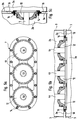
- Fig. 1 is a section of an inventive gas-insulated switchgear shown.
- the switchgear is in its entirety with reference number 1 featured.
- Switchgear 1 is used in particular for Transmission and switching of multi-phase medium voltages. It has three in the detail shown in FIG. 1 next to each other arranged panel arrangements 2.
- a switchgear 1 usually has an average of approximately ten Panel arrangements 2 on.
- the shown in Fig. 1 Switchgear 1 is both on the left and on the right shown without conclusion.
- Each of the panel arrangements 2 has a gas-tight one Gas container 3 on, in the switching elements and at least a busbar 4 are arranged.
- the busbars 4 of the Panel arrangements 2 have for each phase in the Switchgear 1 voltage to be switched a separate Line 4a, 4b, 4c on (see FIG. 2).
- Fig. 1 are the individual lines 4a, 4b, 4c in the drawing plane arranged one behind the other.
- Neighbors Panel arrangements 2a, 2b are on a mechanical connection point 7 mechanically connected with each other.
- the lines 4a, 4b, 4c of the Busbars 4 of the adjacent switch panel arrangements 2a, 2b are at an electrical connection point 11 electrically connected together.
- the ends the lines 4a, 4b, 4c opening into the recesses 12 the busbar 4 close flush with the Recesses 12 surrounding wall 3a of the gas container 3.
- connection opening 10 is on the electrical Junctions 11 for each line 4a, 4b, 4c Contact element 13 for producing an electrical conductive connection between the ends of the lines 4a, 4b, 4c of the busbar 4 of the switchgear arrangement 2a and the ends of the lines 4a, 4b, 4c of the busbar 4 of the adjacent panel arrangement 2b arranged.
- the Contact element 13 consists of an electrically conductive Material. It is designed as a pipeline that the Divided lengthwise into two pipe segments 13a, 13b is. The pipe segments 13a, 13b are on the Lines 4a, 4b, 4c of the busbars 4 of the neighboring ones Panel arrangements 2a, 2b axially displaceable and resilient arranged tense.
- the adjacent panel arrangements 2a, 2b are on the mechanical joints 7 in such a way mechanically connected that the gas container 3 of the Panel arrangements 2a, 2b via the connection opening 10 is gas-tight in connection with the recesses 12.
- the connecting elements 14 are preferably as Screws trained.
- Between a wall 3b of the Gas container 3 of the panel arrangement 2a and the wall 3a of the gas container 3 of the adjacent panel arrangement 2b is around the connection opening 10 and around the recesses 12 around a sealing element 15 is arranged.
- the Sealing element 15 is such between the walls 3a and 3b clamped that the gas container 3 of Panel arrangement 2a through the wall 3a of the gas container 3 of the adjacent panel arrangement 2b gas-tight is closed (see FIG. 4)
- the wall 3b on one of the side 6 of the gas container 3 opposite side 5 is outside around the mechanical Junction 7 around partially as a compliant Area 16 formed.
- the compliant area 16 of the wall 3b surrounds the mechanical connection point 7 in a ring shape. It consists of a thin sheet with a radial one Towards wavy profile.
- the wreath-shaped resilient area 16 is in an opening in wall 3b of the gas container 3 of the Schatlfeldan elbow 2a formed.
- the flexible area 16 is on its outer edge welded to the edge of the opening in the wall 3b. On his inner edge is the resilient area 16 on the mechanical connection point 7 attached. For example, by means of a welded connection or a clamp connection respectively. It is crucial that the flexible area 16 gas-tight between the mechanical connection point 7 and the wall 3b of the gas container 3 is attached.
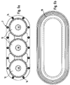
- 5a to 5c are the three lines 4a, 4b, 4c the busbar 4 shown as they are on the side of the Wall 3a of the control panel arrangements 2 from the gas containers 3 stepping out.
- the lines 4a, 4b, 4c of the busbar 4 each lead to a separate recess 12.
- the Connecting elements 14 are around the depressions 12 arranged around and form the mechanical Junction 7.
- Around the junction 7 is the collar-shaped flexible region 16 is arranged (cf. Fig. 6b).
- connecting elements 14 are arranged around the recesses 12 and form several mechanical connection points 7. Then could each have a wreath-like compliant region 16 ⁇ m each connection point 7 may be arranged.
Landscapes
- Engineering & Computer Science (AREA)
- Power Engineering (AREA)
- Gas-Insulated Switchgears (AREA)
Applications Claiming Priority (2)
| Application Number | Priority Date | Filing Date | Title |
|---|---|---|---|
| DE1998150694 DE19850694B4 (de) | 1998-11-04 | 1998-11-04 | Gasisolierte Schaltanlage |
| DE19850694 | 1998-11-04 |
Publications (2)
| Publication Number | Publication Date |
|---|---|
| EP0999624A1 true EP0999624A1 (fr) | 2000-05-10 |
| EP0999624B1 EP0999624B1 (fr) | 2009-02-18 |
Family
ID=7886573
Family Applications (1)
| Application Number | Title | Priority Date | Filing Date |
|---|---|---|---|
| EP19990117087 Expired - Lifetime EP0999624B1 (fr) | 1998-11-04 | 1999-08-31 | Installation de commutation à gaz isolant |
Country Status (2)
| Country | Link |
|---|---|
| EP (1) | EP0999624B1 (fr) |
| DE (2) | DE19850694B4 (fr) |
Cited By (3)
| Publication number | Priority date | Publication date | Assignee | Title |
|---|---|---|---|---|
| EP2254209A1 (fr) * | 2009-05-20 | 2010-11-24 | ABB Technology AG | Raccordements de puissance au primaire enfichables de deux modules d'une installation de commutation haute tension isolée du gaz |
| WO2010133500A1 (fr) * | 2009-05-20 | 2010-11-25 | Abb Technology Ag | Connexions enfichables d'alimentation primaire de deux modules d'un appareillage de commutation haute tension à isolation gazeuse |
| CN102163818A (zh) * | 2010-01-18 | 2011-08-24 | Abb技术有限公司 | 气体绝缘的高压测量单元 |
Families Citing this family (2)
| Publication number | Priority date | Publication date | Assignee | Title |
|---|---|---|---|---|
| DE10246598A1 (de) * | 2002-10-05 | 2004-04-15 | Alstom | Sammelschienenkupplung für eine gasisolierte Schaltanlage |
| CN106786112A (zh) * | 2016-12-28 | 2017-05-31 | 滁州品之达电器科技有限公司 | 一种环保气体绝缘的开关柜 |
Citations (3)
| Publication number | Priority date | Publication date | Assignee | Title |
|---|---|---|---|---|
| FR1499052A (fr) * | 1966-11-15 | 1967-10-20 | Siemens Ag | Poste de distribution électrique à haute tension |
| DE1490673A1 (de) * | 1964-09-30 | 1969-10-23 | Siemens Ag | Elektrische Hochspannungsschaltanlage |
| DE6917852U (de) * | 1969-05-02 | 1971-03-04 | Bbc Brown Boveri & Cie | Anordnung zur gasdichten verbindung zweier rohrfoermiger teile |
Family Cites Families (3)
| Publication number | Priority date | Publication date | Assignee | Title |
|---|---|---|---|---|
| DE1340623U (fr) * | ||||
| KR900002891B1 (ko) * | 1984-12-29 | 1990-05-01 | 미쯔비시 덴끼 가부시기가이샤 | 가스절연 개폐장치 |
| DE4404340A1 (de) * | 1994-02-11 | 1995-08-17 | Sachsenwerk Ag | Schaltanlage mit einem Verbindungskanal |
-
1998
- 1998-11-04 DE DE1998150694 patent/DE19850694B4/de not_active Expired - Fee Related
-
1999
- 1999-08-31 EP EP19990117087 patent/EP0999624B1/fr not_active Expired - Lifetime
- 1999-08-31 DE DE59914965T patent/DE59914965D1/de not_active Expired - Lifetime
Patent Citations (3)
| Publication number | Priority date | Publication date | Assignee | Title |
|---|---|---|---|---|
| DE1490673A1 (de) * | 1964-09-30 | 1969-10-23 | Siemens Ag | Elektrische Hochspannungsschaltanlage |
| FR1499052A (fr) * | 1966-11-15 | 1967-10-20 | Siemens Ag | Poste de distribution électrique à haute tension |
| DE6917852U (de) * | 1969-05-02 | 1971-03-04 | Bbc Brown Boveri & Cie | Anordnung zur gasdichten verbindung zweier rohrfoermiger teile |
Cited By (6)
| Publication number | Priority date | Publication date | Assignee | Title |
|---|---|---|---|---|
| EP2254209A1 (fr) * | 2009-05-20 | 2010-11-24 | ABB Technology AG | Raccordements de puissance au primaire enfichables de deux modules d'une installation de commutation haute tension isolée du gaz |
| WO2010133500A1 (fr) * | 2009-05-20 | 2010-11-25 | Abb Technology Ag | Connexions enfichables d'alimentation primaire de deux modules d'un appareillage de commutation haute tension à isolation gazeuse |
| CN102439807A (zh) * | 2009-05-20 | 2012-05-02 | Abb技术股份有限公司 | 气体绝缘高压开关设备的两个模块的插拔式主电源连接件 |
| US20120138573A1 (en) * | 2009-05-20 | 2012-06-07 | Abb Technology Ag | Plug-in primary power connections of two modules of a gas-insulated high-voltage switchgear assembly |
| US8629367B2 (en) | 2009-05-20 | 2014-01-14 | Abb Technology Ag | Plug-in primary power connections of two modules of a gas-insulated high-voltage switchgear assembly |
| CN102163818A (zh) * | 2010-01-18 | 2011-08-24 | Abb技术有限公司 | 气体绝缘的高压测量单元 |
Also Published As
| Publication number | Publication date |
|---|---|
| DE59914965D1 (de) | 2009-04-02 |
| EP0999624B1 (fr) | 2009-02-18 |
| DE19850694B4 (de) | 2007-04-12 |
| DE19850694A1 (de) | 2000-05-11 |
Similar Documents
| Publication | Publication Date | Title |
|---|---|---|
| DE19716024B4 (de) | Metallgekapselte gasisolierte Schaltanlage | |
| DE8717730U1 (de) | Metallgekapselte, mit Druckgas gefüllte, mehrphasige Hochspannungsschaltanlage | |
| DE1938706A1 (de) | Hochspannungsleitung | |
| DE4001192C2 (de) | Schaltstation im Baukastensystem | |
| DE3230091A1 (de) | Druckgasisolierter stromwandler | |
| DE19815151C1 (de) | Mit einem Ausgleichselement versehener Kapselungsabschnitt einer gasisolierten Hochspannungsanlage und Hochspannungsschaltanlage mit einem solchen Kapselungsabschnitt | |
| EP1547218B1 (fr) | Couplage des barres pour une installation de distribution etanche au gaz | |
| DE2624908C2 (de) | Scheibenförmiger Stützisolator für eine dreiphasig gekapselte, druckgasisolierte Hochspannungsleitung | |
| EP2501002A1 (fr) | Module de montage transversal pour une installation de commutation | |
| EP0083092B1 (fr) | Blindage isolant pour une installation de commutation et de répartition moyenne tension | |
| DE19850694B4 (de) | Gasisolierte Schaltanlage | |
| EP2281331A2 (fr) | Dispositif de boîtier blindé | |
| DE69200142T2 (de) | Elektrische Verbindung, insbesondere für modulare Mittelspannungsanlage. | |
| EP0499606A1 (fr) | Appareillage de distribution haute tension tripolaire sous blindage metallique avec isolation par gaz comprime. | |
| EP0175637B1 (fr) | Connexion conductrice de courant à vis entre conducteurs tubulaires d'une installation électrique, en particulier d'une installation haute tension à blindage métallique | |
| WO2022023272A1 (fr) | Borne de connexion de conducteur, utilisation de celle-ci, et procédé de montage d'une borne de connexion de conducteur | |
| DE2141817C3 (de) | Isoliergasgefüllte gekapselte elektrische Hochspannungsleitung | |
| DE10011888C2 (de) | Dreiphasige Hochspannungsschaltanlage mit einphasig gekapselten Baugruppen | |
| EP4197013B1 (fr) | Changeur de prise en charge et transformateur à changement de prise pourvu d'un changeur de prise en charge | |
| EP0999623B1 (fr) | Installation de commutation à gaz isolant | |
| EP0627800A1 (fr) | Appareillage de commutation blindé métallique à isolement gazeux avec une terminaison de câble | |
| EP2595263A1 (fr) | Commutateur électrique | |
| DE102006040038A1 (de) | Anordnung mit einem Scheibenisolator | |
| DE19959450B4 (de) | Elektrische Steckverbindung, welche sich während der Montage der isoliergasbefüllten Schaltanlagenkomponenten selbsttätig mit Isoliergas befüllt | |
| WO2011110298A2 (fr) | Installation électrique monophasée ou mutiphasée à blindage métallique et isolée aux gaz |
Legal Events
| Date | Code | Title | Description |
|---|---|---|---|
| PUAI | Public reference made under article 153(3) epc to a published international application that has entered the european phase |
Free format text: ORIGINAL CODE: 0009012 |
|
| 17P | Request for examination filed |
Effective date: 19991211 |
|
| AK | Designated contracting states |
Kind code of ref document: A1 Designated state(s): DE ES FR IT |
|
| AX | Request for extension of the european patent |
Free format text: AL;LT;LV;MK;RO;SI |
|
| AKX | Designation fees paid |
Free format text: DE ES FR IT |
|
| RAP1 | Party data changed (applicant data changed or rights of an application transferred) |
Owner name: AREVA SACHSENWERK GMBH |
|
| GRAP | Despatch of communication of intention to grant a patent |
Free format text: ORIGINAL CODE: EPIDOSNIGR1 |
|
| GRAS | Grant fee paid |
Free format text: ORIGINAL CODE: EPIDOSNIGR3 |
|
| GRAA | (expected) grant |
Free format text: ORIGINAL CODE: 0009210 |
|
| AK | Designated contracting states |
Kind code of ref document: B1 Designated state(s): DE ES FR IT |
|
| REF | Corresponds to: |
Ref document number: 59914965 Country of ref document: DE Date of ref document: 20090402 Kind code of ref document: P |
|
| PG25 | Lapsed in a contracting state [announced via postgrant information from national office to epo] |
Ref country code: ES Free format text: LAPSE BECAUSE OF FAILURE TO SUBMIT A TRANSLATION OF THE DESCRIPTION OR TO PAY THE FEE WITHIN THE PRESCRIBED TIME-LIMIT Effective date: 20090529 |
|
| PLBE | No opposition filed within time limit |
Free format text: ORIGINAL CODE: 0009261 |
|
| STAA | Information on the status of an ep patent application or granted ep patent |
Free format text: STATUS: NO OPPOSITION FILED WITHIN TIME LIMIT |
|
| 26N | No opposition filed |
Effective date: 20091119 |
|
| REG | Reference to a national code |
Ref country code: FR Ref legal event code: ST Effective date: 20100430 |
|
| PG25 | Lapsed in a contracting state [announced via postgrant information from national office to epo] |
Ref country code: FR Free format text: LAPSE BECAUSE OF NON-PAYMENT OF DUE FEES Effective date: 20090831 |
|
| PG25 | Lapsed in a contracting state [announced via postgrant information from national office to epo] |
Ref country code: IT Free format text: LAPSE BECAUSE OF FAILURE TO SUBMIT A TRANSLATION OF THE DESCRIPTION OR TO PAY THE FEE WITHIN THE PRESCRIBED TIME-LIMIT Effective date: 20090218 |
|
| REG | Reference to a national code |
Ref country code: DE Ref legal event code: R084 Ref document number: 59914965 Country of ref document: DE |
|
| REG | Reference to a national code |
Ref country code: DE Ref legal event code: R084 Ref document number: 59914965 Country of ref document: DE Effective date: 20110728 |
|
| PGFP | Annual fee paid to national office [announced via postgrant information from national office to epo] |
Ref country code: DE Payment date: 20140729 Year of fee payment: 16 |
|
| REG | Reference to a national code |
Ref country code: DE Ref legal event code: R119 Ref document number: 59914965 Country of ref document: DE |
|
| PG25 | Lapsed in a contracting state [announced via postgrant information from national office to epo] |
Ref country code: DE Free format text: LAPSE BECAUSE OF NON-PAYMENT OF DUE FEES Effective date: 20160301 |