EP2595263A1 - Commutateur électrique - Google Patents
Commutateur électrique Download PDFInfo
- Publication number
- EP2595263A1 EP2595263A1 EP11189359.0A EP11189359A EP2595263A1 EP 2595263 A1 EP2595263 A1 EP 2595263A1 EP 11189359 A EP11189359 A EP 11189359A EP 2595263 A1 EP2595263 A1 EP 2595263A1
- Authority
- EP
- European Patent Office
- Prior art keywords
- ring
- conductor piece
- switching device
- electrical switching
- support insulator
- Prior art date
- Legal status (The legal status is an assumption and is not a legal conclusion. Google has not performed a legal analysis and makes no representation as to the accuracy of the status listed.)
- Granted
Links
Images
Classifications
-
- H—ELECTRICITY
- H02—GENERATION; CONVERSION OR DISTRIBUTION OF ELECTRIC POWER
- H02B—BOARDS, SUBSTATIONS OR SWITCHING ARRANGEMENTS FOR THE SUPPLY OR DISTRIBUTION OF ELECTRIC POWER
- H02B13/00—Arrangement of switchgear in which switches are enclosed in, or structurally associated with, a casing, e.g. cubicle
- H02B13/005—Electrical connection between switchgear cells
-
- H—ELECTRICITY
- H02—GENERATION; CONVERSION OR DISTRIBUTION OF ELECTRIC POWER
- H02G—INSTALLATION OF ELECTRIC CABLES OR LINES, OR OF COMBINED OPTICAL AND ELECTRIC CABLES OR LINES
- H02G5/00—Installations of bus-bars
- H02G5/06—Totally-enclosed installations, e.g. in metal casings
- H02G5/066—Devices for maintaining distance between conductor and enclosure
- H02G5/068—Devices for maintaining distance between conductor and enclosure being part of the junction between two enclosures
-
- H—ELECTRICITY
- H02—GENERATION; CONVERSION OR DISTRIBUTION OF ELECTRIC POWER
- H02B—BOARDS, SUBSTATIONS OR SWITCHING ARRANGEMENTS FOR THE SUPPLY OR DISTRIBUTION OF ELECTRIC POWER
- H02B13/00—Arrangement of switchgear in which switches are enclosed in, or structurally associated with, a casing, e.g. cubicle
- H02B13/02—Arrangement of switchgear in which switches are enclosed in, or structurally associated with, a casing, e.g. cubicle with metal casing
- H02B13/035—Gas-insulated switchgear
-
- H—ELECTRICITY
- H02—GENERATION; CONVERSION OR DISTRIBUTION OF ELECTRIC POWER
- H02B—BOARDS, SUBSTATIONS OR SWITCHING ARRANGEMENTS FOR THE SUPPLY OR DISTRIBUTION OF ELECTRIC POWER
- H02B13/00—Arrangement of switchgear in which switches are enclosed in, or structurally associated with, a casing, e.g. cubicle
- H02B13/02—Arrangement of switchgear in which switches are enclosed in, or structurally associated with, a casing, e.g. cubicle with metal casing
- H02B13/035—Gas-insulated switchgear
- H02B13/045—Details of casing, e.g. gas tightness
-
- H—ELECTRICITY
- H02—GENERATION; CONVERSION OR DISTRIBUTION OF ELECTRIC POWER
- H02G—INSTALLATION OF ELECTRIC CABLES OR LINES, OR OF COMBINED OPTICAL AND ELECTRIC CABLES OR LINES
- H02G5/00—Installations of bus-bars
- H02G5/002—Joints between bus-bars for compensating thermal expansion
Definitions
- the invention relates to an electrical switching device according to the preamble of claim 1.
- a disconnector module 1a is shown, which is closed gas-tight at its right end by a support insulator 9.
- a conductor piece 7 is passed and held, which is aligned in the direction of the other end of the separator module 1a.
- the two ends of the conductor piece 7 are located in the region of the two ends of the separator module 1a.
- a tubular busbar part 2a is flanged gas-tight, in which a further conductor piece 8 is housed.
- the two ends of the conductor piece 8 are located in the region of the two ends of the busbar part 2a.
- a support insulator 9 is again provided, through which a further conductor piece 7 is passed and held.
- the two current conductor pieces 7, 8 are in each case electrically connected to one another via a connecting part 10.
- the connecting part 10 can, for example, according to the figure 3 of DE 24 09 484 C2 be formed, ie in the form of a plunging into a socket connector. By this configuration of the connecting part 10, a thermally induced length expansion of the conductor pieces 7, 8 can be compensated.
- a disadvantage of the known switchgear is that a disconnector module 1a and a busbar part 2a are always associated with two connecting parts 10. At these two connecting parts 10 and at their contact resistances loss energy is generated in the form of heat, which has a reduction in the efficiency of the electrical switchgear result.
- the object of the invention is to overcome the disadvantages of the known switchgear.
- the invention solves this problem by an electrical switching device according to claim 1.
- the electrical switching device has two spaces in which a first conductor piece and optionally further components of the switching device are housed. It is provided a support insulator which separates the two spaces, and through which the first conductor piece is passed. There is a ring associated with the post insulator and through which the first post is passed such that movement of the first post in the ring is possible.
- the invention has the advantage that the first conductor piece is movable relative to the ring and thus also relative to the support insulator.
- thermally induced length expansions of the first conductor piece can be compensated with regard to the support insulator. Since no current flows through the ring and the post insulator, no heat or energy loss can arise there.
- the ring can also be constructed in a simple manner, in particular without the need for complex electrical connection means.
- the electrical connection means can be realized in that the second conductor piece is arranged approximately coaxially and adjacent to the first conductor piece, and that one of the two conductor pieces at its the other conductor piece facing free end has a socket into which the free end of the other conductor piece is inserted. It is expedient if a movement of the other conductor piece is possible within the sleeve connected to the first-mentioned conductor piece. Thus, the mentioned compensation of linear expansion in a simple manner can be achieved.
- a guide ring is present between the first conductor piece and the ring, and / or there is a contact element between the first conductor piece and the ring.
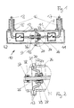
- FIG. 1 shows a schematic sectional view of an embodiment of an electrical according to the invention Switching device
- FIG. 2 shows a section Z from the FIG. 1 in an enlarged view.
- FIG. 1 a phase of an electrical switching device 10 is shown, which is preferably used in high-voltage switchgear.
- the switching device 10 is a so-called encapsulated compressed gas-insulated switching device.
- the switching device 10 has a first and a second metallic housing part 11, 12, which are each tubular and closed on one side. At their open ends, the two housing parts 11, 12 via flanges 13 gas-tightly connected to each other, for example screwed.
- the interior of the two housing parts 11, 12 is filled with an insulating gas, for example with SF6 or N2 or another gas or gas mixture.
- the interior of the two housing parts 11, 12 may also be evacuated, so that there is a vacuum.
- the two housing parts 11, 12 each have an opening 15 on their peripheral surfaces, on each of which a tubular insulator part 16 is placed gas-tight.
- a first and a second electrical conductors 17, 18 gas-tight from the outside into the interior of the two housing parts 11, 12 introduced.
- the electrical conductors 17, 18 are made of an electrically conductive material, in particular of a metal.
- the two conductors 17, 18 are angled so that they are substantially coaxially within the two tubular housing parts 11, 12 are aligned.
- a support insulator 20 is provided, which is configured substantially annular.
- the support insulator 20 is made of an electrically insulating material and has an outer edge 21 and an inner edge 22.
- the support insulator 20 may be made of a casting resin, which in particular has an A1203 admixture.
- the support insulator 20 is formed in the manner of a pot open at the bottom.
- the support insulator 20 is located substantially inside the first housing part 11 or projects into the first housing part 11.
- the support insulator 20 is attached with its outer edge 21 gas-tight on one of the two or both housing parts 11, 12. For example, the outer edge 21 of the support insulator 20 between the flanges 13 of the two housing parts 11, 12 is clamped.
- the support insulator 20 is assigned a ring 24.
- the ring 24 is received in the opening formed by the inner edge 22 of the support insulator 20.
- the ring 24 is held by the post insulator 20.
- the ring 24 is made of an electrically conductive material.
- the ring 24 has an approximately oval cross-sectional area and is gas-tight against the inner edge 22 of the support insulator 20.
- a passage opening 25 is formed, which is aligned substantially coaxially with the two housing parts 11, 12.
- the ring 24 serves to influence the electric field within the two housing parts 11, 12.
- the cross-sectional area of the ring 24 may also be formed differently from the present embodiment.
- the first conductor piece 26 In the passage opening 25 of the ring 24, a first conductor piece 26 is received.
- the first conductor piece 26 consists of an electrically conductive material, for example of a metal.
- the first conductor piece 26 is at least partially rod-shaped or tubular and is aligned with the axis formed in this way substantially coaxially within the two housing parts 11, 12.
- the first conductor piece 26 is located substantially within the first housing part 11 and protrudes only slightly into the second housing part 12.
- the first conductor piece 26 is at least slightly movable back and forth in the ring 24 in the axial direction. For this purpose, at least one slight annular gap is present between the ring 24 and the first conductor piece 26.
- a sealing ring 28 is inserted into a groove of the ring 24.
- the sealing ring 28 is preferably made of an elastomer or the like, preferably rubber.
- the aforementioned annular gap between the ring 24 and the first conductor piece 26 is closed by the sealing ring 28. With the aid of the sealing ring 28 results in a gas-tight connection between the ring 24 and the first conductor piece 26th
- a guide ring 29 can be further embedded in a groove.
- the guide ring 29 may be made of a metal or of a polymer material, for example. If present, then the guide ring 29 is provided to improve the sliding conditions between the ring 24 and the first conductor piece 26. Furthermore, the guide ring 29 can also serve to center the first conductor piece 26 within the ring 24 and / or improve the seal between the ring 24 and the first conductor piece 26.
- the ring 24 may also consist of a material with good sliding properties, for example of PTFE (polytetrafluoroethylene).
- PTFE polytetrafluoroethylene
- the material of the ring 24 influences the sliding and guiding behavior of the first conductor piece 26.
- the guide ring 29 may be omitted under certain circumstances.
- the support insulator 20 and the ring 24 may also be integrally formed.
- the common pillar member is made of an insulating material, for example, a cast resin.
- the sealing ring 28 and / or the guide ring 29 can then be embedded in the casting resin of this common supporter component.
- a contact element 31 may be further embedded in a groove.
- the contact element 31 may be annular or lamellar. If present, the contact element 31 consists of an electrically conductive material. If present, then the contact element 31 is provided to establish an electrical connection between the ring 24 and the first conductor piece 26. By means of this electrical connection, potential differences between the two named components can be avoided without significant currents flowing via the contact element 31.
- a first power switch 33 is housed in the present embodiment.
- One terminal of the first power switch 33 is connected to the first conductor 17 and the other terminal is connected to the first conductor piece 26.
- a second power switch 34 is housed in the present embodiment.
- One terminal of the second power switch 34 is connected to the second conductor 18 and the other terminal is connected to a second conductor piece 36.
- first circuit breaker 33 and / or the second circuit breaker 34 other components of the switching device 10 may be present, such as disconnector switch or disconnector / earthing switch or the like. It is also possible that one of the two switches or both switches is / are not present, and that instead the first conductor 17 and the first conductor piece 26 and / or the second conductor 18 and the second conductor piece 36 are directly connected to each other or in one piece are formed. With the latter alternative spatial distances can be overcome.
- the second conductor piece 36 is rod-shaped or tubular and substantially coaxially aligned within the two housing parts 11, 12.
- the second conductor piece 36 consists of an electrically conductive material and is located within the second housing part 12.
- the first and the second conductor piece 26, 36 are aligned coaxially with each other and their free ends are adjacent to each other.
- the second conductor piece 36 has a socket 37, which is provided to receive the free end of the first conductor piece 26 therein.
- the dimensions of the bushing 37 in the axial direction are provided such that the first conductor piece 26 can move at least slightly in the axial direction within the bushing 37 back and forth.
- electrical connection means 38 are provided, which are adapted to produce an electrical connection with a low contact resistance between the two conductor pieces 26, 36.
- the electrical connection means 38 may be, for example, spring-loaded contacts or the like.
- the free ends of the two conductor pieces 26, 36 may be configured differently. In this regard, it is only essential that on the one hand at least a slight axial relative movement between the two conductor pieces 26, 36 is possible, and that on the other hand an electrical connection with a low contact resistance between the two conductor pieces 26, 36 can be achieved.
- the first conductor 17, the first power switch 33 and the first conductor piece 26 are located in a first gas-tightly sealed space 41, which is essentially delimited by the first housing part 11.
- the second conductor 18, the second power switch 34 and the second conductor piece 36 are located in a second gas-tightly sealed space 42, which is substantially of the second housing part 12th is limited.
- the two spaces 41, 42 are separated by the support insulator 20 gas-tight.
- the two conductors 17, 18 and the two conductor pieces 26, 36 are electrically insulated from the two housing parts 11, 12 with the aid of the insulator parts 16, the support insulator 20 and the existing insulating gas.
- the two housing parts 11, 12 are usually grounded.
- the first conductor piece 26 - as explained was - within the connected to the second conductor piece 36 bushing 37 in the axial direction at least slightly back and forth, and that on the other hand - as also explained - the first conductor piece 26 also within the connected to the support insulator 20 ring 24 at least slightly can move back and forth.
- first conductor piece 26 and the socket 37 of the second conductor piece 36 on the one hand and the first conductor piece 26 and the ring 24 of the support insulator 20 on the other hand can move relative to each other, also manufacturing tolerances can be compensated.
- the two housing parts 11, 12 with the components housed therein can each be manufactured separately.
- the post insulator 20 and the ring 24 are manufactured separately.
- the support insulator 20, for example cast from a casting resin and the ring 24 in the production of the support insulator 20 are cast with, or it may be the support insulator 20 and / or the ring 24 may be formed such that the ring 24 on the finished cast support insulator 20th is pluggable.
- the two mounted housing parts 11, 12 can be joined together with the interposition of the support insulator 20.
- the first conductor piece 26 can be inserted into the socket 37 of the second conductor piece 36.
- the two housing parts 11, 12 are fixed to each other and to the support insulator 20.
- the two chambers 41, 42 are filled with insulating gas. It is understood that it is also possible, instead of the insulating gas to evacuate the housing parts 11, 12 and thus to produce a vacuum in the two chambers 41, 42.
- the switching device 10 is the FIG. 1 single-phase trained. It is understood that multi-phase devices can be constructed in a similar manner.
- the switching device 10 may be placed on a mounting frame in the open and there may form part of a high voltage switchgear.
- sealing rings 28 and / or a plurality of guide rings 29 and / or a plurality of contact elements 31 may be present. It is also possible that the / the sealing ring / e 28 and / or the / the guide ring / e 29 and / or the / the contact element / e 31st not - as explained with reference to the figures - are embedded in the inside of the ring 24, but on the outside of the first conductor piece 26, namely there in the region of the ring 24th
- the bush 37 need not be attached to the second conductor piece 36, as explained with reference to the figures, but may also be attached to the free end of the first conductor piece 26. In this case, the free end of the second conductor piece 36 dips into the socket 37 of the first conductor piece 26.
- the electrical switching device 10 of the Figures 1 and 2 may also have other housing parts and / or spaces in which other and / or other components of the switching device 10 are housed or in which other and / or other functions of the switching device 10 are performed.
Landscapes
- Engineering & Computer Science (AREA)
- Power Engineering (AREA)
- Gas-Insulated Switchgears (AREA)
- Driving Mechanisms And Operating Circuits Of Arc-Extinguishing High-Tension Switches (AREA)
- Automotive Seat Belt Assembly (AREA)
Priority Applications (7)
| Application Number | Priority Date | Filing Date | Title |
|---|---|---|---|
| HUE11189359A HUE028574T2 (en) | 2011-11-16 | 2011-11-16 | Electric switch |
| EP11189359.0A EP2595263B1 (fr) | 2011-11-16 | 2011-11-16 | Commutateur électrique |
| MX2014005819A MX2014005819A (es) | 2011-11-16 | 2012-10-18 | Aparato interruptor electrico. |
| RU2014123774/07A RU2603361C2 (ru) | 2011-11-16 | 2012-10-18 | Электрический коммутационный аппарат |
| PCT/EP2012/070605 WO2013072153A1 (fr) | 2011-11-16 | 2012-10-18 | Commutateur électrique |
| KR1020147015992A KR101819790B1 (ko) | 2011-11-16 | 2012-10-18 | 전기 스위칭 소자 |
| CN 201220609070 CN203135286U (zh) | 2011-11-16 | 2012-11-16 | 电开关装置 |
Applications Claiming Priority (1)
| Application Number | Priority Date | Filing Date | Title |
|---|---|---|---|
| EP11189359.0A EP2595263B1 (fr) | 2011-11-16 | 2011-11-16 | Commutateur électrique |
Publications (3)
| Publication Number | Publication Date |
|---|---|
| EP2595263A1 true EP2595263A1 (fr) | 2013-05-22 |
| EP2595263A8 EP2595263A8 (fr) | 2013-08-14 |
| EP2595263B1 EP2595263B1 (fr) | 2016-03-30 |
Family
ID=47074706
Family Applications (1)
| Application Number | Title | Priority Date | Filing Date |
|---|---|---|---|
| EP11189359.0A Active EP2595263B1 (fr) | 2011-11-16 | 2011-11-16 | Commutateur électrique |
Country Status (7)
| Country | Link |
|---|---|
| EP (1) | EP2595263B1 (fr) |
| KR (1) | KR101819790B1 (fr) |
| CN (1) | CN203135286U (fr) |
| HU (1) | HUE028574T2 (fr) |
| MX (1) | MX2014005819A (fr) |
| RU (1) | RU2603361C2 (fr) |
| WO (1) | WO2013072153A1 (fr) |
Cited By (1)
| Publication number | Priority date | Publication date | Assignee | Title |
|---|---|---|---|---|
| EP3093938A1 (fr) * | 2015-05-12 | 2016-11-16 | Siemens Aktiengesellschaft | Système d'exécution haute tension |
Families Citing this family (2)
| Publication number | Priority date | Publication date | Assignee | Title |
|---|---|---|---|---|
| CN106207908B (zh) * | 2016-08-23 | 2017-12-15 | 国家电网公司 | 管母支撑二通金具及其屏蔽环、屏蔽球冠 |
| RU186262U1 (ru) * | 2018-07-04 | 2019-01-15 | Акционерное общество высоковольтного оборудования "Электроаппарат" (АО ВО "Электроаппарат") | Разъединитель-заземлитель распределительного устройства с газовой изоляцией |
Citations (5)
| Publication number | Priority date | Publication date | Assignee | Title |
|---|---|---|---|---|
| DE2409484C2 (de) | 1973-09-28 | 1982-06-03 | Sprecher & Schuh AG, 5001 Aarau, Aargau | Druckgasisoliertes, gekapseltes Sammelschienensystem mit entfernbaren Stromleitern |
| JPS583717U (ja) * | 1981-06-30 | 1983-01-11 | 三菱電機株式会社 | ガス絶縁電気装置 |
| JPS6082930U (ja) * | 1983-11-09 | 1985-06-08 | 株式会社日立製作所 | 二脚ポストスペ−サに依る導体支持装置 |
| EP0660479A1 (fr) * | 1993-12-21 | 1995-06-28 | Gec Alsthom T Et D Sa | Câble monophase à isolation gazeuse pour le transport d'électricité |
| JPH11273766A (ja) * | 1998-03-19 | 1999-10-08 | Mitsubishi Electric Corp | 接続装置 |
Family Cites Families (1)
| Publication number | Priority date | Publication date | Assignee | Title |
|---|---|---|---|---|
| EP1569254A1 (fr) * | 2004-02-27 | 2005-08-31 | ABB Technology AG | Interrupteur de mise à la terre et/ou sectionneur |
-
2011
- 2011-11-16 EP EP11189359.0A patent/EP2595263B1/fr active Active
- 2011-11-16 HU HUE11189359A patent/HUE028574T2/en unknown
-
2012
- 2012-10-18 WO PCT/EP2012/070605 patent/WO2013072153A1/fr not_active Ceased
- 2012-10-18 RU RU2014123774/07A patent/RU2603361C2/ru active
- 2012-10-18 KR KR1020147015992A patent/KR101819790B1/ko active Active
- 2012-10-18 MX MX2014005819A patent/MX2014005819A/es active IP Right Grant
- 2012-11-16 CN CN 201220609070 patent/CN203135286U/zh not_active Expired - Lifetime
Patent Citations (5)
| Publication number | Priority date | Publication date | Assignee | Title |
|---|---|---|---|---|
| DE2409484C2 (de) | 1973-09-28 | 1982-06-03 | Sprecher & Schuh AG, 5001 Aarau, Aargau | Druckgasisoliertes, gekapseltes Sammelschienensystem mit entfernbaren Stromleitern |
| JPS583717U (ja) * | 1981-06-30 | 1983-01-11 | 三菱電機株式会社 | ガス絶縁電気装置 |
| JPS6082930U (ja) * | 1983-11-09 | 1985-06-08 | 株式会社日立製作所 | 二脚ポストスペ−サに依る導体支持装置 |
| EP0660479A1 (fr) * | 1993-12-21 | 1995-06-28 | Gec Alsthom T Et D Sa | Câble monophase à isolation gazeuse pour le transport d'électricité |
| JPH11273766A (ja) * | 1998-03-19 | 1999-10-08 | Mitsubishi Electric Corp | 接続装置 |
Cited By (1)
| Publication number | Priority date | Publication date | Assignee | Title |
|---|---|---|---|---|
| EP3093938A1 (fr) * | 2015-05-12 | 2016-11-16 | Siemens Aktiengesellschaft | Système d'exécution haute tension |
Also Published As
| Publication number | Publication date |
|---|---|
| WO2013072153A1 (fr) | 2013-05-23 |
| RU2014123774A (ru) | 2015-12-27 |
| HUE028574T2 (en) | 2016-12-28 |
| CN203135286U (zh) | 2013-08-14 |
| MX2014005819A (es) | 2014-10-24 |
| EP2595263B1 (fr) | 2016-03-30 |
| KR20140098784A (ko) | 2014-08-08 |
| RU2603361C2 (ru) | 2016-11-27 |
| KR101819790B1 (ko) | 2018-01-17 |
| EP2595263A8 (fr) | 2013-08-14 |
Similar Documents
| Publication | Publication Date | Title |
|---|---|---|
| EP0744803B1 (fr) | Sectionneur pour une installation de commutation à haute tension, blindé et à isolation gazeuse | |
| DE102007004950B4 (de) | Elektrische Schaltanlage | |
| EP2595263B1 (fr) | Commutateur électrique | |
| DE2924630C2 (de) | Gekapselter, dreiphasiger Drehtrennschalter | |
| EP0205397B1 (fr) | Sectionneur pour une installation interrupteur haute tension blindée et isolée au gaz comprimé | |
| DE10325682A1 (de) | Gasisoliertes Sammelschienenbauteil mit Freiluftdurchführung | |
| DE102016207292B4 (de) | Elektrische Schutzvorrichtung und Transformator mit einer solchen | |
| DE102013216018B4 (de) | Vorrichtung zur Übertragung von Kräften | |
| WO1996013087A1 (fr) | Installation electrique de distribution haute tension a sectionneur de puissance, a blindage metallique | |
| DE102022210985A1 (de) | Basismodul für Hochspannungs-Schaltgeräte mit Vakuumschaltröhren und Hochspannungs-Schaltgerät mit dem Basismodul | |
| WO2012123323A1 (fr) | Système de mise en contact électrique | |
| EP2036178B1 (fr) | Disjoncteur de puissance muni d'un boîtier | |
| DE102020211512A1 (de) | Vakuumschalter | |
| DE102006056656A1 (de) | Schaltermodul für eine elektrische Schaltanlage | |
| DE102006040036A1 (de) | Anordnung mit einem elektrischen Schaltgerät | |
| EP3276647B1 (fr) | Unité de mise à la terre pour une installation de commutation | |
| EP2273525A1 (fr) | Commutateur de puissance électrique | |
| WO2004109877A2 (fr) | Installation de distribution avec des sectionneurs integres dans une traversee exterieure | |
| DE2707592A1 (de) | Steckverbindung | |
| DE102023209613A1 (de) | Anordnung von Vakuumschaltröhren zum Schalten von Hochspannungen | |
| WO2002001585A1 (fr) | Rail de raccordement en demi-produits profiles pour appareils electriques et courant nominaux differents | |
| DE102023207758A1 (de) | Anordnung zum Schalten von Spannungen mit Träger für Steuerelemente | |
| EP3979444A1 (fr) | Dispositif électrique de transfert d'énergie pourvu de dispositif de compensation destiné à la compensation de dilatation et dispositif de compensation correspondant | |
| DE102019209875A1 (de) | Schalteinrichtung | |
| EP3659163A1 (fr) | Ensemble de modules pour le montage de disjoncteurs |
Legal Events
| Date | Code | Title | Description |
|---|---|---|---|
| PUAI | Public reference made under article 153(3) epc to a published international application that has entered the european phase |
Free format text: ORIGINAL CODE: 0009012 |
|
| AK | Designated contracting states |
Kind code of ref document: A1 Designated state(s): AL AT BE BG CH CY CZ DE DK EE ES FI FR GB GR HR HU IE IS IT LI LT LU LV MC MK MT NL NO PL PT RO RS SE SI SK SM TR |
|
| AX | Request for extension of the european patent |
Extension state: BA ME |
|
| RIN1 | Information on inventor provided before grant (corrected) |
Inventor name: REITZ, HILMAR Inventor name: STELTER, ACHIM Inventor name: BIERICH, VICTOR |
|
| 17P | Request for examination filed |
Effective date: 20131107 |
|
| RBV | Designated contracting states (corrected) |
Designated state(s): AL AT BE BG CH CY CZ DE DK EE ES FI FR GB GR HR HU IE IS IT LI LT LU LV MC MK MT NL NO PL PT RO RS SE SI SK SM TR |
|
| GRAP | Despatch of communication of intention to grant a patent |
Free format text: ORIGINAL CODE: EPIDOSNIGR1 |
|
| RIC1 | Information provided on ipc code assigned before grant |
Ipc: H02G 5/00 20060101ALI20150916BHEP Ipc: H02B 13/045 20060101ALN20150916BHEP Ipc: H02B 13/035 20060101ALI20150916BHEP Ipc: H02G 5/06 20060101AFI20150916BHEP |
|
| RIC1 | Information provided on ipc code assigned before grant |
Ipc: H02G 5/06 20060101AFI20151006BHEP Ipc: H02G 5/00 20060101ALI20151006BHEP Ipc: H02B 13/035 20060101ALI20151006BHEP Ipc: H02B 13/045 20060101ALN20151006BHEP |
|
| INTG | Intention to grant announced |
Effective date: 20151021 |
|
| GRAS | Grant fee paid |
Free format text: ORIGINAL CODE: EPIDOSNIGR3 |
|
| RAP1 | Party data changed (applicant data changed or rights of an application transferred) |
Owner name: GENERAL ELECTRIC TECHNOLOGY GMBH |
|
| GRAA | (expected) grant |
Free format text: ORIGINAL CODE: 0009210 |
|
| AK | Designated contracting states |
Kind code of ref document: B1 Designated state(s): AL AT BE BG CH CY CZ DE DK EE ES FI FR GB GR HR HU IE IS IT LI LT LU LV MC MK MT NL NO PL PT RO RS SE SI SK SM TR |
|
| REG | Reference to a national code |
Ref country code: GB Ref legal event code: FG4D Free format text: NOT ENGLISH |
|
| REG | Reference to a national code |
Ref country code: CH Ref legal event code: EP |
|
| REG | Reference to a national code |
Ref country code: AT Ref legal event code: REF Ref document number: 786310 Country of ref document: AT Kind code of ref document: T Effective date: 20160415 |
|
| REG | Reference to a national code |
Ref country code: IE Ref legal event code: FG4D Free format text: LANGUAGE OF EP DOCUMENT: GERMAN |
|
| REG | Reference to a national code |
Ref country code: DE Ref legal event code: R096 Ref document number: 502011009243 Country of ref document: DE |
|
| REG | Reference to a national code |
Ref country code: CH Ref legal event code: NV Representative=s name: DREISS PATENTANWAELTE PARTG MBB, DE |
|
| REG | Reference to a national code |
Ref country code: SE Ref legal event code: TRGR |
|
| REG | Reference to a national code |
Ref country code: LT Ref legal event code: MG4D |
|
| PG25 | Lapsed in a contracting state [announced via postgrant information from national office to epo] |
Ref country code: NO Free format text: LAPSE BECAUSE OF FAILURE TO SUBMIT A TRANSLATION OF THE DESCRIPTION OR TO PAY THE FEE WITHIN THE PRESCRIBED TIME-LIMIT Effective date: 20160630 Ref country code: HR Free format text: LAPSE BECAUSE OF FAILURE TO SUBMIT A TRANSLATION OF THE DESCRIPTION OR TO PAY THE FEE WITHIN THE PRESCRIBED TIME-LIMIT Effective date: 20160330 Ref country code: GR Free format text: LAPSE BECAUSE OF FAILURE TO SUBMIT A TRANSLATION OF THE DESCRIPTION OR TO PAY THE FEE WITHIN THE PRESCRIBED TIME-LIMIT Effective date: 20160701 Ref country code: FI Free format text: LAPSE BECAUSE OF FAILURE TO SUBMIT A TRANSLATION OF THE DESCRIPTION OR TO PAY THE FEE WITHIN THE PRESCRIBED TIME-LIMIT Effective date: 20160330 |
|
| REG | Reference to a national code |
Ref country code: NL Ref legal event code: MP Effective date: 20160330 |
|
| PG25 | Lapsed in a contracting state [announced via postgrant information from national office to epo] |
Ref country code: RS Free format text: LAPSE BECAUSE OF FAILURE TO SUBMIT A TRANSLATION OF THE DESCRIPTION OR TO PAY THE FEE WITHIN THE PRESCRIBED TIME-LIMIT Effective date: 20160330 Ref country code: LV Free format text: LAPSE BECAUSE OF FAILURE TO SUBMIT A TRANSLATION OF THE DESCRIPTION OR TO PAY THE FEE WITHIN THE PRESCRIBED TIME-LIMIT Effective date: 20160330 Ref country code: LT Free format text: LAPSE BECAUSE OF FAILURE TO SUBMIT A TRANSLATION OF THE DESCRIPTION OR TO PAY THE FEE WITHIN THE PRESCRIBED TIME-LIMIT Effective date: 20160330 |
|
| PG25 | Lapsed in a contracting state [announced via postgrant information from national office to epo] |
Ref country code: NL Free format text: LAPSE BECAUSE OF FAILURE TO SUBMIT A TRANSLATION OF THE DESCRIPTION OR TO PAY THE FEE WITHIN THE PRESCRIBED TIME-LIMIT Effective date: 20160330 |
|
| PG25 | Lapsed in a contracting state [announced via postgrant information from national office to epo] |
Ref country code: PL Free format text: LAPSE BECAUSE OF FAILURE TO SUBMIT A TRANSLATION OF THE DESCRIPTION OR TO PAY THE FEE WITHIN THE PRESCRIBED TIME-LIMIT Effective date: 20160330 Ref country code: IS Free format text: LAPSE BECAUSE OF FAILURE TO SUBMIT A TRANSLATION OF THE DESCRIPTION OR TO PAY THE FEE WITHIN THE PRESCRIBED TIME-LIMIT Effective date: 20160730 Ref country code: EE Free format text: LAPSE BECAUSE OF FAILURE TO SUBMIT A TRANSLATION OF THE DESCRIPTION OR TO PAY THE FEE WITHIN THE PRESCRIBED TIME-LIMIT Effective date: 20160330 |
|
| REG | Reference to a national code |
Ref country code: FR Ref legal event code: PLFP Year of fee payment: 6 |
|
| PG25 | Lapsed in a contracting state [announced via postgrant information from national office to epo] |
Ref country code: CZ Free format text: LAPSE BECAUSE OF FAILURE TO SUBMIT A TRANSLATION OF THE DESCRIPTION OR TO PAY THE FEE WITHIN THE PRESCRIBED TIME-LIMIT Effective date: 20160330 Ref country code: SM Free format text: LAPSE BECAUSE OF FAILURE TO SUBMIT A TRANSLATION OF THE DESCRIPTION OR TO PAY THE FEE WITHIN THE PRESCRIBED TIME-LIMIT Effective date: 20160330 Ref country code: PT Free format text: LAPSE BECAUSE OF FAILURE TO SUBMIT A TRANSLATION OF THE DESCRIPTION OR TO PAY THE FEE WITHIN THE PRESCRIBED TIME-LIMIT Effective date: 20160801 Ref country code: ES Free format text: LAPSE BECAUSE OF FAILURE TO SUBMIT A TRANSLATION OF THE DESCRIPTION OR TO PAY THE FEE WITHIN THE PRESCRIBED TIME-LIMIT Effective date: 20160330 Ref country code: RO Free format text: LAPSE BECAUSE OF FAILURE TO SUBMIT A TRANSLATION OF THE DESCRIPTION OR TO PAY THE FEE WITHIN THE PRESCRIBED TIME-LIMIT Effective date: 20160330 Ref country code: SK Free format text: LAPSE BECAUSE OF FAILURE TO SUBMIT A TRANSLATION OF THE DESCRIPTION OR TO PAY THE FEE WITHIN THE PRESCRIBED TIME-LIMIT Effective date: 20160330 |
|
| REG | Reference to a national code |
Ref country code: HU Ref legal event code: AG4A Ref document number: E028574 Country of ref document: HU |
|
| REG | Reference to a national code |
Ref country code: DE Ref legal event code: R097 Ref document number: 502011009243 Country of ref document: DE |
|
| PG25 | Lapsed in a contracting state [announced via postgrant information from national office to epo] |
Ref country code: DK Free format text: LAPSE BECAUSE OF FAILURE TO SUBMIT A TRANSLATION OF THE DESCRIPTION OR TO PAY THE FEE WITHIN THE PRESCRIBED TIME-LIMIT Effective date: 20160330 |
|
| PLBE | No opposition filed within time limit |
Free format text: ORIGINAL CODE: 0009261 |
|
| STAA | Information on the status of an ep patent application or granted ep patent |
Free format text: STATUS: NO OPPOSITION FILED WITHIN TIME LIMIT |
|
| PG25 | Lapsed in a contracting state [announced via postgrant information from national office to epo] |
Ref country code: BE Free format text: LAPSE BECAUSE OF NON-PAYMENT OF DUE FEES Effective date: 20161130 |
|
| 26N | No opposition filed |
Effective date: 20170103 |
|
| PG25 | Lapsed in a contracting state [announced via postgrant information from national office to epo] |
Ref country code: SI Free format text: LAPSE BECAUSE OF FAILURE TO SUBMIT A TRANSLATION OF THE DESCRIPTION OR TO PAY THE FEE WITHIN THE PRESCRIBED TIME-LIMIT Effective date: 20160330 |
|
| GBPC | Gb: european patent ceased through non-payment of renewal fee |
Effective date: 20161116 |
|
| REG | Reference to a national code |
Ref country code: IE Ref legal event code: MM4A |
|
| PG25 | Lapsed in a contracting state [announced via postgrant information from national office to epo] |
Ref country code: LU Free format text: LAPSE BECAUSE OF NON-PAYMENT OF DUE FEES Effective date: 20161130 |
|
| REG | Reference to a national code |
Ref country code: FR Ref legal event code: PLFP Year of fee payment: 7 |
|
| PG25 | Lapsed in a contracting state [announced via postgrant information from national office to epo] |
Ref country code: GB Free format text: LAPSE BECAUSE OF NON-PAYMENT OF DUE FEES Effective date: 20161116 Ref country code: IE Free format text: LAPSE BECAUSE OF NON-PAYMENT OF DUE FEES Effective date: 20161116 |
|
| REG | Reference to a national code |
Ref country code: AT Ref legal event code: MM01 Ref document number: 786310 Country of ref document: AT Kind code of ref document: T Effective date: 20161116 |
|
| PG25 | Lapsed in a contracting state [announced via postgrant information from national office to epo] |
Ref country code: AT Free format text: LAPSE BECAUSE OF NON-PAYMENT OF DUE FEES Effective date: 20161116 |
|
| REG | Reference to a national code |
Ref country code: BE Ref legal event code: MM Effective date: 20161130 |
|
| PG25 | Lapsed in a contracting state [announced via postgrant information from national office to epo] |
Ref country code: CY Free format text: LAPSE BECAUSE OF FAILURE TO SUBMIT A TRANSLATION OF THE DESCRIPTION OR TO PAY THE FEE WITHIN THE PRESCRIBED TIME-LIMIT Effective date: 20160330 |
|
| PG25 | Lapsed in a contracting state [announced via postgrant information from national office to epo] |
Ref country code: MC Free format text: LAPSE BECAUSE OF FAILURE TO SUBMIT A TRANSLATION OF THE DESCRIPTION OR TO PAY THE FEE WITHIN THE PRESCRIBED TIME-LIMIT Effective date: 20160330 Ref country code: TR Free format text: LAPSE BECAUSE OF FAILURE TO SUBMIT A TRANSLATION OF THE DESCRIPTION OR TO PAY THE FEE WITHIN THE PRESCRIBED TIME-LIMIT Effective date: 20160330 Ref country code: MK Free format text: LAPSE BECAUSE OF FAILURE TO SUBMIT A TRANSLATION OF THE DESCRIPTION OR TO PAY THE FEE WITHIN THE PRESCRIBED TIME-LIMIT Effective date: 20160330 |
|
| PG25 | Lapsed in a contracting state [announced via postgrant information from national office to epo] |
Ref country code: BG Free format text: LAPSE BECAUSE OF FAILURE TO SUBMIT A TRANSLATION OF THE DESCRIPTION OR TO PAY THE FEE WITHIN THE PRESCRIBED TIME-LIMIT Effective date: 20160330 |
|
| PG25 | Lapsed in a contracting state [announced via postgrant information from national office to epo] |
Ref country code: MT Free format text: LAPSE BECAUSE OF FAILURE TO SUBMIT A TRANSLATION OF THE DESCRIPTION OR TO PAY THE FEE WITHIN THE PRESCRIBED TIME-LIMIT Effective date: 20160330 |
|
| REG | Reference to a national code |
Ref country code: FR Ref legal event code: PLFP Year of fee payment: 8 |
|
| PG25 | Lapsed in a contracting state [announced via postgrant information from national office to epo] |
Ref country code: AL Free format text: LAPSE BECAUSE OF FAILURE TO SUBMIT A TRANSLATION OF THE DESCRIPTION OR TO PAY THE FEE WITHIN THE PRESCRIBED TIME-LIMIT Effective date: 20160330 |
|
| PGFP | Annual fee paid to national office [announced via postgrant information from national office to epo] |
Ref country code: FR Payment date: 20191022 Year of fee payment: 9 |
|
| PG25 | Lapsed in a contracting state [announced via postgrant information from national office to epo] |
Ref country code: FR Free format text: LAPSE BECAUSE OF NON-PAYMENT OF DUE FEES Effective date: 20201130 |
|
| P01 | Opt-out of the competence of the unified patent court (upc) registered |
Effective date: 20230522 |
|
| REG | Reference to a national code |
Ref country code: CH Ref legal event code: U11 Free format text: ST27 STATUS EVENT CODE: U-0-0-U10-U11 (AS PROVIDED BY THE NATIONAL OFFICE) Effective date: 20251201 |
|
| PGFP | Annual fee paid to national office [announced via postgrant information from national office to epo] |
Ref country code: HU Payment date: 20251117 Year of fee payment: 15 |
|
| PGFP | Annual fee paid to national office [announced via postgrant information from national office to epo] |
Ref country code: DE Payment date: 20251022 Year of fee payment: 15 |
|
| PGFP | Annual fee paid to national office [announced via postgrant information from national office to epo] |
Ref country code: IT Payment date: 20251022 Year of fee payment: 15 |
|
| PGFP | Annual fee paid to national office [announced via postgrant information from national office to epo] |
Ref country code: CH Payment date: 20251201 Year of fee payment: 15 Ref country code: SE Payment date: 20251022 Year of fee payment: 15 |