EP1000707A2 - Ecrou de fixation - Google Patents
Ecrou de fixation Download PDFInfo
- Publication number
- EP1000707A2 EP1000707A2 EP19990121130 EP99121130A EP1000707A2 EP 1000707 A2 EP1000707 A2 EP 1000707A2 EP 19990121130 EP19990121130 EP 19990121130 EP 99121130 A EP99121130 A EP 99121130A EP 1000707 A2 EP1000707 A2 EP 1000707A2
- Authority
- EP
- European Patent Office
- Prior art keywords
- clamping nut
- ring
- cover
- spindle
- nut
- Prior art date
- Legal status (The legal status is an assumption and is not a legal conclusion. Google has not performed a legal analysis and makes no representation as to the accuracy of the status listed.)
- Withdrawn
Links
- 238000003754 machining Methods 0.000 description 2
- 239000000463 material Substances 0.000 description 2
- 238000011084 recovery Methods 0.000 description 2
- 238000005096 rolling process Methods 0.000 description 2
- 229910000831 Steel Inorganic materials 0.000 description 1
- 238000004519 manufacturing process Methods 0.000 description 1
- 230000007246 mechanism Effects 0.000 description 1
- 238000000034 method Methods 0.000 description 1
- 230000002093 peripheral effect Effects 0.000 description 1
- 239000004033 plastic Substances 0.000 description 1
- 230000035939 shock Effects 0.000 description 1
- 239000010959 steel Substances 0.000 description 1
Images
Classifications
-
- B—PERFORMING OPERATIONS; TRANSPORTING
- B24—GRINDING; POLISHING
- B24B—MACHINES, DEVICES, OR PROCESSES FOR GRINDING OR POLISHING; DRESSING OR CONDITIONING OF ABRADING SURFACES; FEEDING OF GRINDING, POLISHING, OR LAPPING AGENTS
- B24B23/00—Portable grinding machines, e.g. hand-guided; Accessories therefor
- B24B23/02—Portable grinding machines, e.g. hand-guided; Accessories therefor with rotating grinding tools; Accessories therefor
- B24B23/028—Angle tools
-
- B—PERFORMING OPERATIONS; TRANSPORTING
- B24—GRINDING; POLISHING
- B24B—MACHINES, DEVICES, OR PROCESSES FOR GRINDING OR POLISHING; DRESSING OR CONDITIONING OF ABRADING SURFACES; FEEDING OF GRINDING, POLISHING, OR LAPPING AGENTS
- B24B45/00—Means for securing grinding wheels on rotary arbors
Definitions
- the present invention relates to a clamping nut for releasable fastening a disk-shaped tool in particular on a driven one Spindle of a hand machine tool, especially an angle grinder.
- a grinding machine has become known from DE 36 13 987 C2, with a one-piece clamping nut on the end of the spindle is screwed to the grinding wheel between a flange and the Clamping nut.
- a contact of the rotating spindle or the rotating one Clamping nut with the workpiece to be machined is disadvantageous because on the one hand damage to the workpiece can occur and on the other hand the There is a risk of tilting, with the result that the angle grinder cannot be kept under control.
- the object of the present invention is therefore to avoid that the rotating Clamping nut during the operation of the hand machine tool in Contact with the workpiece to be machined.
- a ring-shaped embracing the clamping nut Cover is provided opposite the clamping nut around the spindle is rotatably arranged around. While working with the hand machine tool it is guaranteed that not the clamping nut itself with the machining tool can come into contact, but only the cover. Since the cover is rotatable, it remains in contact with the workpiece stand still with the tension nut underneath. Damage to the Workpiece are therefore excluded. Furthermore, there is no longer a risk that shock loads due to unwanted contact of the Clamping nut with the workpiece an uncontrolled handling of the angle grinder have as a consequence.
- the cover can be, for example, a cap that is attached to the End face of the clamping nut facing away from the grinding wheel is attached. The the complete face of the clamping nut is then covered.
- This cap can continue to be provided with an axial ridge, which is towards the Grinding wheel extends, the outer diameter of the axial rim larger than the outside diameter of the tension nut. This also ensures that with a radial movement, the cap or its axial rim first comes into contact with the workpiece. But it may also be enough that the cover is provided in the edge area of the clamping nut, i.e. wherever Cut the circumferential and end faces of the clamping nut.
- the cover can also be arranged concentrically on the clamping nut be cylindrical sleeve formed with its facing away from the tool Axially protrudes from the end face of the clamping nut. That means, that the workpiece to be machined is not with the front of the Clamping nut, but in contact with this front end of the sleeve is coming.
- the sleeve can completely enclose the clamping nut.
- a development according to the invention provides that a concentric to the spindle arranged, forming the cover angular ring on that of the End of the clamping nut facing away from the tool is rotatably fastened, the Axialbord of the angle ring has an outer diameter that is larger than the outer diameter of the clamping nut and its radial rim is an inner diameter has that is smaller than the outer diameter of the clamping nut is.
- the angle ring preferably covers the edge area of the clamping nut and prevents the peripheral and frontal contact of the Clamping nut with the workpiece to be machined.
- the cover can be opposite the clamping nut by means of a roller bearing be rotatably mounted.
- a plain bearing is also an alternative conceivable.
- the cover and the clamping nut each are provided with a ball groove on which balls roll.
- Ball bearings can be the clear radial in a particularly advantageous manner Distance between the two ball grooves smaller than the diameter of the ball his. This means that the cover is captive on the clamping nut is held without additional means to provide the cover to fix the clamping nut rotatably.
- the clear radial distance by resilient Deformation of the cover is expandable so that the balls in their ball grooves get or snap there.
- the cover snaps So on the clamping nut, with the balls under elastic recovery the cover get into their ball grooves.
- the present invention is suitable for clamping nuts which are essentially are made in one piece, for example for a clamping nut, such as that has already been described at the beginning of the prior art.
- the invention Clamping nut can also be made in several parts.
- Such multi-part clamping nuts are also designed as quick-release nuts, the mechanisms include the clamping pressure on the grinding wheel reduce before unscrewing the clamping nut from the spindle. In this way you save yourself the use of an additional tool, to loosen the tension nut.
- a development according to the invention provides that the cover by a plain bearing ring is formed, which is slidably mounted with respect to the clamping nut is.
- This variant has the advantage that the number of individual parts used is further reduced.
- the materials for the plain bearing ring and the clamping nut can be chosen such that good sliding contact is ensured in sliding contact is.
- the plain bearing ring has an outer diameter, which is larger than the outside diameter of the clamping nut.
- the plain bearing ring attached to the clamping nut so that it is attached to the protrudes axially away from the tool end. If the clamping nut is radial or is moved axially onto the workpiece to be machined, a contact is made between workpiece and plain bearing ring instead of the light plain bearing ring is braked quickly and stands still relative to the workpiece.
- the clamping nut concentric with the spindle Has shoulder on which the plain bearing ring rests and with which the plain bearing ring is in sliding contact.
- the plain bearing ring and the shoulder can also be used on the front and circumferentially opposite sliding surfaces. In this way it is ensured that the outside of the slide bearing ring acting forces in the axial and radial direction of the plain bearing ring properly is supported and stored.
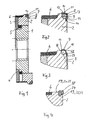
- the multi-part clamping nut shown in Figure 1 consists essentially from a nut part 1, which on the spindle, not shown, of an angle grinder is screwed on.
- the nut part 1 is non-rotatable and axial slidably arranged a ring 2.
- one is on the nut part 1 a rotatably arranged disc 3 for contacting the one not shown Grinding wheel provided.
- the disc 3 and the nut part 1 limit facing end faces a circumferential wedge-shaped gap 4, that tapers radially inward.
- This gap 4 is a slotted spring washer 5 arranged, which is biased radially inwards.
- the spring washer 5 is supported with its outer circumference on the ring 2 and presses against the the end faces delimiting the gap 4.
- a rubber ring 6 - the can also be formed from a material other than rubber, provided that it is easily deformable - provided that the nut part 1 and the Disc 3 includes.
- an angular ring 7 is provided, which over an angular contact ball bearing 8 Ring 2 is roller-bearing. This area is shown in FIG. 2 as an enlarged detail pictured.
- the angular contact ball bearing 8 comprises balls 9 and ball grooves 10, 11.
- the ball groove 10 is on the ring 2 and the ball groove 11 is on the Angle ring 7 formed.
- the axial rim 12 of the angle ring 7 extends in Direction on the grinding wheel, not shown, and the radial rim 13 extends radially inward.
- the outer diameter of the axial flange 12 is larger than the outside diameter of the clamping nut or ring 2.
- the inside diameter of the radial rim is smaller than the outside diameter of the Rings 2.
- the angle ring 7 the edge area of the ring 2 covers all around.
- the free end of the radial rim 13 will overlapped by a projection 14 of the ring 2.
- This projection 14 can be circumferential, but it is also sufficient to arrange several distributed over the circumference to provide point-like projections. These projections can, for example be stamped. This ensures that the angle ring 7 is captively connected to the ring 2.
- the inventive clamping nut shown in Figure 3 differs differs from that of Figure 2 essentially by a different attachment of the angle ring 7 on the ring 2.
- FIG. 3 shows that the free end of the axial rim 12 is retracted radially, and that one on the Ring 2 formed ball groove 16 merges into a raised shoulder 17.
- the radial clear distance 11 between the ball grooves 15, 16 and between the free end of the axial rim 12 and the shoulder 17 of the ring 2 is smaller than the diameter of the ball 9.
- the angle ring 7 can be mounted as follows, for example:
- the angle ring 12 is pressed axially against the ring 2, which is radial retracted free end of the axial rim 12 of the angle ring 7 above the Ball center rests on the balls 9.
- Axial force deviates axially 12 radially outward; finally the radially retracted end of the axial flange 12 overcomes the apex the balls 9 and the balls 9 snap under elastic recovery of the axial flange 12 into the ball groove 15 of the angle ring 7.
- the angle ring 7 are mounted accordingly, the balls 9 then on the shoulder 17th of the ring 2 are pressed over, and the axial rim 12 radially evades outside. So that the axial flange 12 can be expanded, it can be expanded on several Places distributed over its circumference with fine axially directed Slots. It is also conceivable that the angle ring 7 itself has the required elastic preformability without these slots being required would be. For example, it can be made of thin-walled steel his. However, the use of a plastic is also conceivable.
- Figure 4 shows a further variant according to the invention in a representation like in Figure 3.
- a plain bearing ring 18 provided on a shoulder 19 of the ring 2 axially and radially is supported.
- the plain bearing ring 18 and the shoulder 19 are with the front and sliding surfaces 20, 21, 22, 23 facing one another on the circumference.
- the Ring 2 is provided at its front end with a projection 24 which protrudes radially from the plane of the circumferential sliding surfaces 22, 23 and engages behind the plain bearing ring 18.
- the plain bearing is 18th captively connected to ring 2.
- the clamping nut according to the invention for example an angle grinder is used to ensure that an undesirable Contact between the clamping nut or ring 2 and the machining workpiece by interposing the angle ring 7 or the plain bearing ring 18 is reliably excluded.
Landscapes
- Engineering & Computer Science (AREA)
- Mechanical Engineering (AREA)
- Constituent Portions Of Griding Lathes, Driving, Sensing And Control (AREA)
Applications Claiming Priority (2)
| Application Number | Priority Date | Filing Date | Title |
|---|---|---|---|
| DE1998151917 DE19851917A1 (de) | 1998-11-11 | 1998-11-11 | Spannmutter |
| DE19851917 | 1998-11-11 |
Publications (1)
| Publication Number | Publication Date |
|---|---|
| EP1000707A2 true EP1000707A2 (fr) | 2000-05-17 |
Family
ID=7887370
Family Applications (1)
| Application Number | Title | Priority Date | Filing Date |
|---|---|---|---|
| EP19990121130 Withdrawn EP1000707A2 (fr) | 1998-11-11 | 1999-10-22 | Ecrou de fixation |
Country Status (2)
| Country | Link |
|---|---|
| EP (1) | EP1000707A2 (fr) |
| DE (1) | DE19851917A1 (fr) |
Cited By (1)
| Publication number | Priority date | Publication date | Assignee | Title |
|---|---|---|---|---|
| WO2012003997A1 (fr) | 2010-07-09 | 2012-01-12 | Martin Vorbach | Dispositif et procédé de traitement de données |
Families Citing this family (2)
| Publication number | Priority date | Publication date | Assignee | Title |
|---|---|---|---|---|
| DE20111438U1 (de) | 2001-07-10 | 2001-10-18 | Welz, Hans-Peter, 90473 Nürnberg | Schleifaufsatz für Schleif- oder Poliermaschinen |
| US6571661B1 (en) * | 2002-01-31 | 2003-06-03 | Visteon Global Technologies, Inc. | Brake pedal design |
Family Cites Families (3)
| Publication number | Priority date | Publication date | Assignee | Title |
|---|---|---|---|---|
| DE3012836C2 (de) * | 1980-04-02 | 1985-09-26 | Licentia Patent-Verwaltungs-Gmbh, 6000 Frankfurt | Einrichtung zum Festspannen der Schleifscheibe von Winkelschleifern |
| DE4236964A1 (de) * | 1992-11-02 | 1994-05-05 | Hilti Ag | Scheibenförmiges Werkzeug für Winkelschleifer |
| SE510972C2 (sv) * | 1996-05-07 | 1999-07-19 | Atlas Copco Tools Ab | Portabelt kraftverktyg med balanseringsanordning |
-
1998
- 1998-11-11 DE DE1998151917 patent/DE19851917A1/de not_active Withdrawn
-
1999
- 1999-10-22 EP EP19990121130 patent/EP1000707A2/fr not_active Withdrawn
Cited By (1)
| Publication number | Priority date | Publication date | Assignee | Title |
|---|---|---|---|---|
| WO2012003997A1 (fr) | 2010-07-09 | 2012-01-12 | Martin Vorbach | Dispositif et procédé de traitement de données |
Also Published As
| Publication number | Publication date |
|---|---|
| DE19851917A1 (de) | 2000-05-18 |
Similar Documents
| Publication | Publication Date | Title |
|---|---|---|
| EP0370212B1 (fr) | Ecrou avec anneau de serrage | |
| DE19644968B4 (de) | Fahrradlenkanordnung | |
| DE2326018C3 (de) | Kugelgelenk, insbesondere für Lenkgestänge von Kraftfahrzeugen | |
| DE102016207867B4 (de) | Keilfreilaufkupplung mit radial äußeren Rampen | |
| DE3132443C2 (fr) | ||
| EP0942802B1 (fr) | Machine-outil a commande manuelle | |
| DE3841181A1 (de) | Handwerkzeugmaschine mit einer mehrteiligen handbetaetigbaren schnellspanneinrichtung | |
| EP3509872B1 (fr) | Roue ferroviaire élastique en plusieurs parties | |
| DE69413220T2 (de) | Befestigungsvorrichtung von schleifscheiben | |
| EP0779443B1 (fr) | Corps de palier avec capuchon protecteur | |
| DE3435175A1 (de) | Verschleisseinrichtung fuer entrindungstrommeln | |
| EP2072201B1 (fr) | Palpeur d'angle | |
| DE102004024153A1 (de) | Spannfutter | |
| DE69703347T2 (de) | Übertragungsgelenkkreuz und entsprechendes übertragungsgelenk | |
| EP1000707A2 (fr) | Ecrou de fixation | |
| EP1600259B1 (fr) | Dispositif de serrage pour tendre un objet contre une butée | |
| DE10343572A1 (de) | Aufprallweiche Lagerung einer Antriebswelle eines Scheibenwischers an einem Fahrzeug | |
| DE2619335A1 (de) | Anordnung zur abdichtung von lagern, insbesondere von waelzlagern an foerderbandtragrollen, vorzugsweise des untertagebetriebes | |
| DE1400767B2 (de) | Sicherungsvorrichtung mit federnder, gewölbter Sicherungsscheibe | |
| EP1200230B1 (fr) | Dispositif de serrage pour fixer de maniere liberable une piece sur un arbre | |
| DE10202203B4 (de) | Radlagerbefestigung, insbesondere für ein Kraftfahrzeug | |
| DE2221944A1 (de) | Kombiniertes Saug- und Ablassventil fuer hydraulische Teleskopstossdaempfer | |
| DE8717375U1 (de) | Gewindebohrvorrichtung | |
| DE19518924C2 (de) | Abziehvorrichtung für Kegelrollenlager | |
| DE202019100668U1 (de) | Zwei elastische Ringkörper aufweisende Drehachsenanordnung für eine Lenkrolle |
Legal Events
| Date | Code | Title | Description |
|---|---|---|---|
| PUAI | Public reference made under article 153(3) epc to a published international application that has entered the european phase |
Free format text: ORIGINAL CODE: 0009012 |
|
| 17P | Request for examination filed |
Effective date: 19991022 |
|
| AK | Designated contracting states |
Kind code of ref document: A2 Designated state(s): AT BE CH CY DE DK ES FI FR GB GR IE IT LI LU MC NL PT SE |
|
| AX | Request for extension of the european patent |
Free format text: AL;LT;LV;MK;RO;SI |
|
| STAA | Information on the status of an ep patent application or granted ep patent |
Free format text: STATUS: THE APPLICATION IS DEEMED TO BE WITHDRAWN |
|
| 18D | Application deemed to be withdrawn |
Effective date: 20020503 |