EP1000748A1 - Appareil d'enregistrement à jet d'encre et calotte pour un tel appareil - Google Patents
Appareil d'enregistrement à jet d'encre et calotte pour un tel appareil Download PDFInfo
- Publication number
- EP1000748A1 EP1000748A1 EP99121305A EP99121305A EP1000748A1 EP 1000748 A1 EP1000748 A1 EP 1000748A1 EP 99121305 A EP99121305 A EP 99121305A EP 99121305 A EP99121305 A EP 99121305A EP 1000748 A1 EP1000748 A1 EP 1000748A1
- Authority
- EP
- European Patent Office
- Prior art keywords
- ink
- cap
- suction
- absorbing member
- opening
- Prior art date
- Legal status (The legal status is an assumption and is not a legal conclusion. Google has not performed a legal analysis and makes no representation as to the accuracy of the status listed.)
- Granted
Links
- 238000007599 discharging Methods 0.000 claims abstract description 9
- 238000007789 sealing Methods 0.000 claims abstract description 6
- 239000000976 ink Substances 0.000 description 134
- 238000011084 recovery Methods 0.000 description 17
- 238000010276 construction Methods 0.000 description 7
- 239000007788 liquid Substances 0.000 description 7
- 238000007711 solidification Methods 0.000 description 6
- 230000008023 solidification Effects 0.000 description 6
- 230000007774 longterm Effects 0.000 description 5
- 230000002093 peripheral effect Effects 0.000 description 4
- 239000000758 substrate Substances 0.000 description 4
- 238000000034 method Methods 0.000 description 3
- 238000007639 printing Methods 0.000 description 3
- 206010044565 Tremor Diseases 0.000 description 2
- 238000004891 communication Methods 0.000 description 2
- 230000003111 delayed effect Effects 0.000 description 2
- 238000001035 drying Methods 0.000 description 2
- 230000000694 effects Effects 0.000 description 2
- 239000011148 porous material Substances 0.000 description 2
- 230000035939 shock Effects 0.000 description 2
- 230000001360 synchronised effect Effects 0.000 description 2
- 238000010521 absorption reaction Methods 0.000 description 1
- 229910052782 aluminium Inorganic materials 0.000 description 1
- XAGFODPZIPBFFR-UHFFFAOYSA-N aluminium Chemical compound [Al] XAGFODPZIPBFFR-UHFFFAOYSA-N 0.000 description 1
- 239000000919 ceramic Substances 0.000 description 1
- 239000003086 colorant Substances 0.000 description 1
- 239000002131 composite material Substances 0.000 description 1
- 230000003247 decreasing effect Effects 0.000 description 1
- 238000009429 electrical wiring Methods 0.000 description 1
- 230000005611 electricity Effects 0.000 description 1
- 239000004744 fabric Substances 0.000 description 1
- 239000000835 fiber Substances 0.000 description 1
- 239000011521 glass Substances 0.000 description 1
- 239000010985 leather Substances 0.000 description 1
- 239000000463 material Substances 0.000 description 1
- 229910052751 metal Inorganic materials 0.000 description 1
- 239000002184 metal Substances 0.000 description 1
- 238000012856 packing Methods 0.000 description 1
- 239000000049 pigment Substances 0.000 description 1
- 239000004033 plastic Substances 0.000 description 1
- 229920001296 polysiloxane Polymers 0.000 description 1
- 238000001454 recorded image Methods 0.000 description 1
- 230000001846 repelling effect Effects 0.000 description 1
- 239000011347 resin Substances 0.000 description 1
- 229920005989 resin Polymers 0.000 description 1
- 230000002441 reversible effect Effects 0.000 description 1
- 230000008016 vaporization Effects 0.000 description 1
- 238000009834 vaporization Methods 0.000 description 1
- 239000002699 waste material Substances 0.000 description 1
- XLYOFNOQVPJJNP-UHFFFAOYSA-N water Substances O XLYOFNOQVPJJNP-UHFFFAOYSA-N 0.000 description 1
- 239000002023 wood Substances 0.000 description 1
Images





Classifications
-
- B—PERFORMING OPERATIONS; TRANSPORTING
- B41—PRINTING; LINING MACHINES; TYPEWRITERS; STAMPS
- B41J—TYPEWRITERS; SELECTIVE PRINTING MECHANISMS, i.e. MECHANISMS PRINTING OTHERWISE THAN FROM A FORME; CORRECTION OF TYPOGRAPHICAL ERRORS
- B41J2/00—Typewriters or selective printing mechanisms characterised by the printing or marking process for which they are designed
- B41J2/005—Typewriters or selective printing mechanisms characterised by the printing or marking process for which they are designed characterised by bringing liquid or particles selectively into contact with a printing material
- B41J2/01—Ink jet
- B41J2/135—Nozzles
- B41J2/165—Prevention or detection of nozzle clogging, e.g. cleaning, capping or moistening for nozzles
- B41J2/16505—Caps, spittoons or covers for cleaning or preventing drying out
- B41J2/16508—Caps, spittoons or covers for cleaning or preventing drying out connected with the printer frame
Definitions
- the present invention relates to an ink jet recording apparatus for effecting recording on a recording medium by discharging ink from a recording means, and a cap for such an apparatus.
- the present invention can be applied to an apparatus such as a printer, a copying machine, a facsimile having a communication system or a word processor having a printer portion for effecting recording on a recording medium such as a paper sheet, thread, fibers, cloth leather, metal, plastic, glass, wood or ceramics and to an industrial recording apparatus in which various processing devices are combined in a composite manner.
- a recording medium such as a paper sheet, thread, fibers, cloth leather, metal, plastic, glass, wood or ceramics
- the word "recording” means not only to afford an image such as characters or figures which are meaningful to a recording medium but also to afford an image such as a pattern which is meaningless to a recording medium.
- An ink jet recording system has been used with printers and copying machines because of low noise, low running cost, easiness of compactness and easiness of colorization.
- ink jet recording apparatus for the purpose of preventing ink clogging of discharge ports of a recording head due to solidification of ink or increase in ink viscosity caused by the drying of ink, the discharge ports of the recording head have been shielded from atmosphere, or, for the purpose of recovering clogging of discharge ports due to solidification of ink or increase in ink viscosity or bubbles or foreign matters generated in liquid passages, a suction recovering operation for forcibly discharging ink by generating pressure at the discharge openings has been performed.
- a cap member is closely contacted with a discharge port surface of a recording head and ink is sucked from the recording head by generating negative pressure within the cap member and thereafter the ink remaining in the cap is sucked (idle suction) by communicating the interior of the cap with the atmosphere.
- an ink absorbing member made of porous material for absorbing the ink is disposed within the cap member.
- ink jet recording systems high quality recorded images have been requested and improvement in water-resistance and light-resistance of ink has been made.
- various inks such as ink which becomes water-soluble (to water) after drying or ink including pigment as coloring agent have been used.
- Some of such inks increases its viscosity to loose fluidity (for example, becomes gel) after it is dried due to vaporization.
- An object of the present invention is to provide an ink jet recording apparatus and a cap for such an apparatus, in which, even when discharge ports of a recording head are sealed for a long term, a recovering operation for the recording head can surely be effected.
- Another object of the present invention is to provide an ink jet recording apparatus comprising a cap member capable of sealing discharge ports of a recording head and being provided at its bottom with an ink suction opening and an atmosphere communicating opening, an ink absorbing member disposed within the cap member, a suction pump communicated with the ink suction opening, and an atmosphere opening valve communicated with the atmosphere communicating opening, and wherein areas of the ink absorbing member opposed to the ink suction opening and the atmosphere communicating opening are thinner than the other area and the ink absorbing member abuts against the ink suction opening.
- a further object of the present invention is to provide a cap for an ink jet recording apparatus comprising a cap member capable of sealing discharge ports of a recording head and being provided at its bottom with an ink suction opening communicated with a suction pump and an atmosphere communicating opening communicated with an atmosphere opening valve, and an ink absorbing member disposed within the cap member, and wherein areas of the ink absorbing member opposed to the ink suction opening and the atmosphere communicating opening are thinner than the other area and the ink absorbing member abuts against the ink suction opening.
- ink when ink is sucked from the recording head, an amount of ink remaining in the ink absorbing member can be reduced. Even when the apparats is left as it is for a long term without recording, occurrence of ink solidification and clogging of the ink absorbing member can be reduced. If ink solidification or clogging should be partially generated in the ink absorbing member, after the ink starts to flow once, solidified or clogged ink becomes apt to be solved again from the thinner area of the ink absorbing member.
- the atmosphere can easily be communicated with the interior of the ink absorbing member, thereby effecting the suction of the residual ink (idle suction) positively.
- the recovering operation for the recording head can be effected positively.
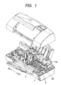
- Fig. 1 is a perspective view showing the entire construction of an ink jet recording apparatus according to a first embodiment of the present invention
- Fig. 2 is a perspective view showing a carriage of Fig. 1 and a recovering unit for a recording head mounted on the carriage
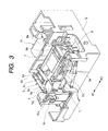
- Fig. 3 is a perspective view showing the entire construction of the recovering unit of Fig. 2.
- Figs. 4 and 5 are sectional views showing a main portion of the recovering unit of Fig. 2
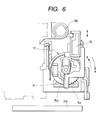
- Fig. 6 is a schematic side view of the recovering unit of Fig. 2
- Fig. 7 is an explanatory view for explaining a recovering operation of the recovering unit of Fig.
- Fig. 8 is a top view of a cap in the recovering unit of Fig. 2
- Fig. 9 is a sectional view taken along the line 9 - 9 in Fig. 8.
- a carriage 2 can be shifted along a guide shaft 101 in a main scanning direction perpendicular to a recording sheet conveying direction.
- the carriage 2 is mounted on the guide shaft 101 by inserting a bearing 100 at a rear part of the carriage onto the guide shaft.
- Two heads of different type are mounted on the carriage 2, and such two heads are deviated from each other, for example by about 4 mm, in the recording sheet conveying direction.
- One of two heads is a photo-head 111 having tanks for magenta and cyan inks having low density and an ink tank for black ink, and a color head 112 capable of discharging yellow, magenta and cyan inks.
- the recording apparatus can effect printing with six color inks, thereby permitting sharp photograph like printing.
- the recording apparatus can effect printing with six color inks, thereby permitting sharp photograph like printing.
- text printing can be effected at a high speed or business color can be printed at a high speed.
- the ink jet recording apparatus is provided with a recovery base 12 having a cap slider 8 (Fig. 3) for capping two heads mounted on the carriage 2 to effect recovering treatment, which recovery base is located at a predetermined position within a main body of the apparatus near a right side thereof (near the arrow A2).
- the cap slider 8 on the recovery base 12 can be slidingly shifted together with the carriage 2 when a projection 8a of the slider is pushed by the moving carriage 2.
- the cap slider 8 is provided with a cap holder 7 holding caps 6a, 6b for covering discharge port forming surfaces of two recording heads 111, 112.
- the cap holder 7 can be shifted in the direction A2 while being lifted, with the result that the discharge port forming surfaces of the recording heads 111, 112 are capped by the caps 6a, 6b.
- a suction pump (recovery treating means) 11 for generating negative pressure in the caps 6a, 6b contacted with two recording heads 111, 112 when capped, so that recovering treatment for sucking the ink which does not contribute to image recording from the discharge ports of the recording heads by negative pressure is effected.
- the recovery base 12 is provided with a wiper holder base 5, and a wiper 3 is held by a wiper holder 4 provided on the wiper holder base 5.
- the wiper 3 can clean the discharge port forming surfaces of two recording heads 111, 112. While the wiper holder base 5 is being slid in synchronous with the cap slider 8, it is lifted by a guiding action between a guide groove 5a of the base and a pin 12c of the recovery base 12.
- the wiper 3 is formed from rubber sheet.
- inks can be discharged from discharge ports (discharge downwardly) formed in the discharge port forming surfaces thereof.
- a plurality of discharge ports are arranged in a line on each discharge port forming surface along a direction transverse to the main scanning direction (shown by the double-headed arrow A1, A2).
- the recording heads 111, 112 may be designed to have electrical/thermal converters for applying thermal energy to discharge the ink from the discharge ports, for example.
- a home position HP(6) (Fig. 7) for the recording heads is located at a position rightwardly (toward the direction A2) of and out of a recording area of the recording medium, and predetermined recovering operation is effected in an area between an idle suction position (1) and a wiper turn position (7) including the home position (6).
- the recording area is located leftwardly (toward the direction A1) of the position (7).
- "DISTANCE (mm)” indicates a shifting distance of the carriage and "NUMBER OF PULSE(S)” indicates the number of pulses of a pulse motor for shifting the carriage. Operating contents in various positions will be described later.
- the suction pump 11 is a tube pump disclosed in Japanese Patent Laid-Open No. 8-318624 (1996).
- the suction pump 11 has sub-roller holders (roller holding means) 14a, 14b for two systems.
- sub-rollers (rollers) 13a, 13b of the sub-roller holders 14a, 14b are shifted while squeezing suction tubes (elastic tubes) 10a, 10b connected to the caps 6a, 6b to generate negative pressures in the caps 6a, 6b, thereby effecting the suction recovery of the recording heads 111, 112.
- a tube guide surface (guide member) 12a of the recovery base 12 has a semi-circular shape.
- the suction sub-roller 13a is relatively shifted along a cam 14c of the sub-roller holder 14a in a direction shown by the arrow b and is held near an outer periphery of the sub-roller holder 14a by an end (directing toward the direction b) of the cam 14c.
- the suction sub-roller 13a is rotated in the direction a together with the sub-roller holder 14a.
- the suction sub-roller 13a squeezes the suction tube 10a disposed between the tube guide surface 12a of the recovery base 12 and the suction sub-roller 13a, thereby generating the negative pressure in the cap 6b to which the suction tube 10a is connected.
- dampers (elastic members) 18a, 18b are provided in a confronting relation to the tube guide surface 12a. The dampers 18a, 18b are mounted to a pump cover 19 which is supported by the recovery base 12.
- the dampers 18a, 18b are located on a rotation path of the sub-roller 13a.
- the suction sub-roller 13a is always biased toward the outer periphery of the cam 14c by an elastic force of the damper to urge the tube 10a.
- the suction sub-roller 13a is released from the suction tube 10a, the suction sub-roller tries to shift inwardly from the outer periphery of the cam 14c by an elastic force (repelling force) of the suction tube 10a.
- the suction sub-roller 13a may abut against an inner peripheral end of the cam 14c to generate collision noise.
- the damper 18b is provided so that the suction sub-roller 13a is prevented from shifting up to the inner peripheral end of the cam 14c.
- shock may not be absorbed to generate tremble noise between the suction sub-roller and the cam 14c.
- the tube guide surface 12a is extended toward a direction perpendicular to a line connecting between the rotation center of the sub-roller holder 14a and the position where the suction sub-roller 13a is released from the suction tube 10a.
- the other sub-roller holder 14b is rotated in the direction a in Fig. 5, and the suction sub-roller 13b is shifted inwardly along a groove-shaped cam 14d of the sub-roller holder 14b and is rotated together with the sub-roller holder 14b at a position where the suction tube 10b is not sealingly closed. Accordingly, the interior of the cap 6a communicated with the suction tube 10b is communicated with the atmosphere.
- the suction sub-roller 13b is relatively shifted along the cam 14b in the direction a and is held near an outer periphery of the sub-roller holder 14b by an end (directing toward the direction a) of the cam 14d.
- the suction sub-roller 13b is rotated in the direction b together with the sub-roller holder 14b.
- the suction sub-roller 13b squeezes the suction tube 10b disposed between the tube guide surface 12a of the recovery base 12 and the suction sub-roller 13b, thereby generating the negative pressure in the cap 6a to which the suction tube 10b is connected.
- dampers (elastic members) 18c, 18d are provided in a confronting relation to the tube guide surface 12a. Similar to the dampers 18a, 18b shown in Fig. 4, the dampers 18c, 18d are mounted to the pump cover 19 and are located on a rotation path of the sub-roller 13b. With this arrangement, as the sub-roller holder 14b is rotated in the direction b in Fig.
- the suction sub-roller 13b when the suction sub-roller 13b contacts with the damper 18c or 18d, the suction sub-roller 13b is always biased toward the outer periphery of the cam 14d by an elastic force of the damper to urge the tube 10b.
- the suction sub-roller 13b When the suction sub-roller 13b is released from the suction tube 10b, the suction sub-roller tries to shift inwardly from the outer periphery of the cam 14d by an elastic force of the suction tube 10b. In this case, the suction sub-roller 13b may abut against an inner peripheral end of the cam 14d to generate collision noise.
- the damper 18d is provided so that the suction sub-roller 13b is prevented from shifting up to the inner peripheral end of the cam 14d.
- the tube guide surface 12a is extended toward a direction perpendicular to a line connecting between the rotation center of the sub-roller holder 14b and the position where the suction sub-roller 13b is released from the suction tube 10b.
- the other sub-roller holder 14a is rotated in the direction b in Fig. 4, and the suction sub-roller 13a is shifted along the cam 14c of the sub-roller holder 14a and is held radially inwardly of the sub-roller holder 14a by an end (directing toward the direction a in Fig. 4) of the cam 14c.
- the suction sub-roller is rotated together with the sub-roller holder 14a in the direction b in Fig. 4.
- the suction sub-roller 13a is rotated to a position where the suction tube 10a is not sealingly closed, with the result that the suction tube 10a is not squeezed.
- the negative pressure is not generated in the suction tube 10a and the interior of the cap 6b communicated with the suction tube 10a is communicated with the atmosphere.
- a carriage lock 15 shown in Fig. 6 is lifted via a friction member 15a to lock movement of the carriage 2, and, when the suction pump 11 is operated in a reverse direction (direction a in Figs. 4 to 6), the carriage lock is lowered via the friction member 15a to unlock the movement of the carriage 2.
- the caps 6a, 6b are held by the cap holder 7, and the cap holder 7 is held by the cap slider 8 via a cap spring (not shown).
- the cap holder 7 is lifted to cause the caps 6a, 6b to cap the recording heads 111, 112.
- Each of the caps 6a, 6b is provided with two holes, and one of two holes in the cap 6a is connected to one end of the suction tube 10b, and the other hole is connected to one end of an atmosphere communicating tube 9b.
- One of two holes in the cap 6b is connected to one end of the suction tube 10a, and the other hole is connected to one end of an atmosphere communicating tube 9a.
- valves 17 are attached to such the other ends via packing members 17a.
- Each valve 17 is opened and closed by its sliding movement when it is pushed by the cap slider 8, so that it is closed at a position (2) in Fig. 7 and is opened at a position (1). Accordingly, in the position (position (2) in Fig. 7) where the heads are capped and the atmosphere communicating tube 9a, 9b are closed, in accordance with the rotational directions of the sub-roller holders 14a, 14b obtained by the suction pump 11, the recovering operation for sucking the ink from the discharge ports of the recording heads 111, 112 through the suction tubes 10a, 10b is permitted. Further, in the position (position (1) in Fig.
- the other ends of the suction tubes 10a, 10b act as ink discharge ends 10-1a, 10-1b, and the ink discharged from the ink discharge ends 10-1a, 10-1b is sent to a waste ink processing member 210 disposed below the ink discharge ends and are processed there.
- Figs. 8 and 9 show the caps 6a, 6b in detail, where Fig. 8 is a top view and Fig. 9 is a sectional view taken along the line 9 - 9 in Fig. 8, showing a condition that the discharge ports of the recording heads 111, 112 are sealingly closed by the caps (elastic members) 6a, 6b.
- each of the caps 6a, 6b is provided at its bottom with two communication holes which act as an ink suction opening 6c and an atmosphere communicating opening 6d, respectively.
- an ink absorbing members 20 made of porous material are disposed within the caps 6a, 6b.
- the ink absorbing members 20 are disposed to contact with inner surfaces of the caps 6a, 6b and abut against the ink suction openings 6c and the atmosphere communicating openings 6d. Areas of each ink absorbing member 20 opposed to the ink suction hole and the atmosphere communicating hole of the cap 6a or 5b have thicknesses thinner than the other area.
- the ink suction openings have substantially the same diameters at areas thereof contacted with the ink absorbing members.
- the ink suction opening and the atmosphere communicating opening are symmetrically arranged in the vicinity of both longitudinal ends of the cap member.
- a central area of the ink absorbing member with respect to the longitudinal direction of the cap member has a thickness greater than those of other areas.
- the longitudinal direction of the cap member substantially coincides with a direction along which the plurality of discharge ports are arranged in a line.
- the thickness of the ink absorbing member is selected to 2.6 mm, and thickness of the areas of the ink absorbing member opposed to the ink suction hole and the atmosphere communicating hole of the cap member is selected to 1.3 mm.
- the atmosphere can easily be communicated with the interior of the ink absorbing members 20, thereby effecting the suction of the residual ink (idle suction) positively.
- a position (position (5) in Fig. 7) where the caps 6a, 6b are spaced apart from and disposed below the recording heads 111, 112 pre-discharge for discharging the ink not contributing the recording from the recording heads 111, 112 can be performed. Further, in a position (4) a in Fig. 7 ASF (auto sheet feeder) trigger for automatically feeding the recording media can be outputted.
- ASF auto sheet feeder
- the cap slider 8 and the wiper holder base 5 are operated in synchronous with each other, so that, when the carriage 2 is situated rightwardly (toward the direction A2) beyond the position (4) in Fig. 7, the wiper holder base 5 is lifted, by the guide groove 5a and the pin 12c of the recovery base 12, up to a position where the wiper holder base can abut against the recording heads 111, 112, with the result that the wiper lock 16 is engaged by the pawl of the recovery base 12. That is to say, when the carriage 2 is shifted from the left to the right beyond the position (4) in Fig. 7, at his position (4), the wiper 3 is held at a position where the wiper can abut against the head. On the other hand, when the carriage 2 is shifted from the right to the left beyond the position (7) in Fig. 7, at his position (7), the wiper lock 16 is unlocked, with the result that the wiper 3 does not contact with the heads 111, 112.
- the suction pump 11 is rotated in the normal direction (direction a) by a drive source (not shown), with the result that the locking condition of the carriage 2 attained by the carriage lock 15 is released or unlocked.
- the carriage 2 is shifted to the wiper turn position (7) in Fig. 7.
- the wiping start (trigger) position (4) is located between the cap position (3) and the recording waiting position (PII) 5. While the carriage 2 is being shifted to the recording waiting position (6), the caps 6a, 6b are opened and the wiping operation for the recording heads 111, 112 is effected by the wiper 3.
- the wiper 3 is provided with four slits 3a, 3b, 3c, 3d.
- the slit 3a is formed at a position corresponding to one of opposed sides of the recording head 112
- the slit 3c is formed at a position corresponding to the other of opposed sides of the recording head 112
- the slit 3b is formed at a position corresponding to one of opposed sides of the recording head 111
- the slit 3c is formed at a position corresponding to the other of opposed sides of the recording head 111.
- the slits 3a, 3b, 3c, 3d are straightly formed in a predetermined area of the sheet-shaped wiper 3 directing from an upper end to a lower end thereof at a position opposed to the opposed sides of the recording head 112 and the opposed sides of the recording head 111.
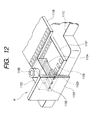
- Figs. 10 and 11 show a cap of a recovering unit of an ink jet recording apparatus according to the second embodiment of the present invention, where Fig. 10 is a top view of the cap and Fig. 11 is a sectional view taken along the line 11 - 11 in Fig. 10.
- the configuration of the ink absorbing member differs from that in the first embodiment. That is to say, in the first embodiment, while an example that the ink absorbing members 20 abut against the ink suction holes and the atmosphere communicating holes formed in the bottoms of the caps 6a, 6b was explained, in the second embodiment, as shown in Fig. 11, an ink absorbing member 21 abuts against the ink suction hole but does not abut against the atmosphere communicating hole. Further, similar to the first embodiment, a thickness of areas of the ink absorbing member 21 opposed to the ink suction hole and the atmosphere communicating hole of the cap 6a or 6b is thinner than a thickness of the other area.
- a top plate 1100 forming a part of the ink jet recording head H is formed from resin material and integrally includes a top plate member having a liquid chamber 1104 for reserving recording liquid and a plurality of liquid passages 1103, a discharge port forming member 1101 having a plurality of discharge ports (orifices) 1102 communicated with the plurality of liquid passages 1103, respectively, and a recording liquid supplying port member 1105.
- a heater board (element substrate) 1107 a plurality of heaters (electrical/thermal converters) 1106 disposed on a silicone substrate and electrical wirings (not shown) made of aluminum or the like for supplying electricity to the heaters are formed by a well-known film forming technique, and the heater board is positioned and secured onto a base plate 1110 by a well-known die-bonding technique.
- a wiring substrate 1108 is provided with wirings connected to the wirings of the heaters board 1107 by a well-known wire-bonding technique, and a plurality of pads 1109 disposed at ends of the wirings and adapted to receive electrical signals from a main body of the image forming apparatus.
- the top plate 1100 and the heater board 1107 are joined together in such a manner that the liquid passages 1103 are opposed to the heaters 1106 to form an assembly, and the assembly is secured to the base plate 1110 together with the wiring substrate 1108, thereby forming the ink jet recording head H.
- the present invention provides an ink jet recording apparatus comprising a cap member capable of sealing a discharge port for discharging ink and being provided at its bottom with an ink suction opening and an atmosphere communicating opening, an ink absorbing member disposed within the cap member, a suction pump communicated with the ink suction opening, and an atmosphere communicating valve communicated with the atmosphere communicating opening, and wherein areas of the ink absorbing member opposed to the ink suction opening and the atmosphere communicating opening are thinner than the other area and the ink absorbing member abuts against the ink suction opening.
Landscapes
- Ink Jet (AREA)
Applications Claiming Priority (2)
| Application Number | Priority Date | Filing Date | Title |
|---|---|---|---|
| JP30617798 | 1998-10-27 | ||
| JP30617798 | 1998-10-27 |
Publications (2)
| Publication Number | Publication Date |
|---|---|
| EP1000748A1 true EP1000748A1 (fr) | 2000-05-17 |
| EP1000748B1 EP1000748B1 (fr) | 2005-08-03 |
Family
ID=17953975
Family Applications (1)
| Application Number | Title | Priority Date | Filing Date |
|---|---|---|---|
| EP99121305A Expired - Lifetime EP1000748B1 (fr) | 1998-10-27 | 1999-10-26 | Appareil d'enregistrement à jet d'encre et calotte pour un tel appareil |
Country Status (3)
| Country | Link |
|---|---|
| US (1) | US6179404B1 (fr) |
| EP (1) | EP1000748B1 (fr) |
| DE (1) | DE69926467T2 (fr) |
Cited By (2)
| Publication number | Priority date | Publication date | Assignee | Title |
|---|---|---|---|---|
| EP1174269A1 (fr) * | 2000-07-21 | 2002-01-23 | Canon Kabushiki Kaisha | Installation de récupération et appareil d'enregistrement à jet d'encre |
| EP1780022A1 (fr) * | 2005-10-31 | 2007-05-02 | SII Printek Inc | Appareil d'enregistrement à jet d'encre |
Families Citing this family (8)
| Publication number | Priority date | Publication date | Assignee | Title |
|---|---|---|---|---|
| JP2002103637A (ja) | 2000-09-29 | 2002-04-09 | Canon Inc | インクジェット記録装置 |
| JP4944296B2 (ja) | 2000-11-01 | 2012-05-30 | キヤノン株式会社 | インクジェット記録装置及び吐出回復方法 |
| JP4626264B2 (ja) * | 2004-10-28 | 2011-02-02 | ブラザー工業株式会社 | 記録ヘッドの保管装置および保管方法 |
| US8172360B2 (en) * | 2008-02-27 | 2012-05-08 | Hewlett-Packard Development Company, L.P. | Printhead servicing system and method |
| DE102008035679B4 (de) * | 2008-07-30 | 2014-05-08 | Francotyp-Postalia Gmbh | Vorrichtung zur Reinigung von Wischelementen für einen Tintendruckkopf |
| US8398205B2 (en) * | 2010-06-25 | 2013-03-19 | Hewlett-Packard Development Company, L.P. | Wiping device for inkjet printers |
| JP7247526B2 (ja) * | 2018-11-13 | 2023-03-29 | セイコーエプソン株式会社 | キャップ、液体噴射装置 |
| JP2022072513A (ja) * | 2020-10-30 | 2022-05-17 | キヤノン株式会社 | 記録装置およびその制御方法 |
Citations (2)
| Publication number | Priority date | Publication date | Assignee | Title |
|---|---|---|---|---|
| EP0435666A2 (fr) * | 1989-12-29 | 1991-07-03 | Canon Kabushiki Kaisha | Dispositif de récupération par aspiration et appareil d'enregistrement à jet d'encre comportant le dispositif |
| EP0744294A1 (fr) * | 1995-05-25 | 1996-11-27 | Seiko Epson Corporation | Dispositif de recouvrement pour une tête d'impression à jet d'encre |
Family Cites Families (6)
| Publication number | Priority date | Publication date | Assignee | Title |
|---|---|---|---|---|
| ATE164552T1 (de) | 1991-01-11 | 1998-04-15 | Canon Kk | Tintenstrahlaufzeichnungsgerät |
| JP3255528B2 (ja) | 1993-12-30 | 2002-02-12 | キヤノン株式会社 | インクジェット装置 |
| JP3291903B2 (ja) * | 1994-04-25 | 2002-06-17 | セイコーエプソン株式会社 | インクジェット記録装置 |
| JP3285074B2 (ja) | 1995-05-25 | 2002-05-27 | セイコーエプソン株式会社 | インクジェット式記録装置 |
| JPH10244707A (ja) | 1997-03-03 | 1998-09-14 | Canon Inc | 光偏向走査装置 |
| JPH11138855A (ja) | 1997-11-14 | 1999-05-25 | Canon Inc | インクジェットプリントヘッド用キャップおよび該キャップを用いるインクジェットプリント装置 |
-
1999
- 1999-10-22 US US09/422,794 patent/US6179404B1/en not_active Expired - Fee Related
- 1999-10-26 DE DE69926467T patent/DE69926467T2/de not_active Expired - Lifetime
- 1999-10-26 EP EP99121305A patent/EP1000748B1/fr not_active Expired - Lifetime
Patent Citations (2)
| Publication number | Priority date | Publication date | Assignee | Title |
|---|---|---|---|---|
| EP0435666A2 (fr) * | 1989-12-29 | 1991-07-03 | Canon Kabushiki Kaisha | Dispositif de récupération par aspiration et appareil d'enregistrement à jet d'encre comportant le dispositif |
| EP0744294A1 (fr) * | 1995-05-25 | 1996-11-27 | Seiko Epson Corporation | Dispositif de recouvrement pour une tête d'impression à jet d'encre |
Cited By (4)
| Publication number | Priority date | Publication date | Assignee | Title |
|---|---|---|---|---|
| EP1174269A1 (fr) * | 2000-07-21 | 2002-01-23 | Canon Kabushiki Kaisha | Installation de récupération et appareil d'enregistrement à jet d'encre |
| US6641249B2 (en) | 2000-07-21 | 2003-11-04 | Canon Kabushiki Kaisha | Recovery unit and ink jet recording apparatus |
| EP1780022A1 (fr) * | 2005-10-31 | 2007-05-02 | SII Printek Inc | Appareil d'enregistrement à jet d'encre |
| US8152266B2 (en) | 2005-10-31 | 2012-04-10 | Sii Printek Inc. | Inkjet recording apparatus |
Also Published As
| Publication number | Publication date |
|---|---|
| DE69926467T2 (de) | 2006-04-20 |
| DE69926467D1 (de) | 2005-09-08 |
| EP1000748B1 (fr) | 2005-08-03 |
| US6179404B1 (en) | 2001-01-30 |
Similar Documents
| Publication | Publication Date | Title |
|---|---|---|
| EP1369242B1 (fr) | Dispositif d'enregistrement par jet d'encre et sa partie de nettoyage | |
| EP0552030B1 (fr) | Mécanisme de recouvrement pour un appareil d'enregistrement à jet d'encre | |
| US7926905B2 (en) | Ink jet recording apparatus | |
| EP1000748B1 (fr) | Appareil d'enregistrement à jet d'encre et calotte pour un tel appareil | |
| JP2000127439A (ja) | 廃インクタンクおよびインクジェット記録装置 | |
| US7059713B2 (en) | Inkjet printing apparatus and ink printing method | |
| JPH10157153A (ja) | インクジェット記録装置 | |
| JP2002225312A (ja) | インクジェット記録装置 | |
| JPH0820114A (ja) | インクジェット記録装置 | |
| JP3100451B2 (ja) | インクジェット記録装置 | |
| JP2002225313A (ja) | インクジェット記録装置 | |
| JP2004050472A (ja) | インクジェット記録装置 | |
| JP2002086746A (ja) | インク吐出回復装置及びインクジェット記録装置 | |
| US7073887B2 (en) | Ink-jet printing apparatus | |
| JPH11342625A (ja) | インクジェット記録装置 | |
| JP2002096457A (ja) | インクジェットプリンタ | |
| JP2000198213A (ja) | インクジェット記録装置およびインクジェット記録装置用キャップ | |
| JPH09262975A (ja) | インクジェット記録装置 | |
| JP2007022036A (ja) | 記録ヘッドおよびインクジェット記録装置 | |
| JP2008001011A (ja) | インクジェット記録装置 | |
| JP2004230711A (ja) | インクジェット記録装置のキャッピング機構 | |
| JP2000185414A (ja) | インクジェット記録装置 | |
| JP2002331673A (ja) | インクジェット記録装置及び該記録装置に用いるキャッピング機構 | |
| JP3025089B2 (ja) | インクジェット記録装置 | |
| JPH06336029A (ja) | インクジェット記録装置 |
Legal Events
| Date | Code | Title | Description |
|---|---|---|---|
| PUAI | Public reference made under article 153(3) epc to a published international application that has entered the european phase |
Free format text: ORIGINAL CODE: 0009012 |
|
| AK | Designated contracting states |
Kind code of ref document: A1 Designated state(s): DE ES FR GB IT NL |
|
| AX | Request for extension of the european patent |
Free format text: AL;LT;LV;MK;RO;SI |
|
| 17P | Request for examination filed |
Effective date: 20001004 |
|
| AKX | Designation fees paid |
Free format text: DE ES FR GB IT NL |
|
| GRAP | Despatch of communication of intention to grant a patent |
Free format text: ORIGINAL CODE: EPIDOSNIGR1 |
|
| GRAS | Grant fee paid |
Free format text: ORIGINAL CODE: EPIDOSNIGR3 |
|
| GRAA | (expected) grant |
Free format text: ORIGINAL CODE: 0009210 |
|
| AK | Designated contracting states |
Kind code of ref document: B1 Designated state(s): DE ES FR GB IT NL |
|
| PG25 | Lapsed in a contracting state [announced via postgrant information from national office to epo] |
Ref country code: NL Free format text: LAPSE BECAUSE OF FAILURE TO SUBMIT A TRANSLATION OF THE DESCRIPTION OR TO PAY THE FEE WITHIN THE PRESCRIBED TIME-LIMIT Effective date: 20050803 Ref country code: IT Free format text: LAPSE BECAUSE OF FAILURE TO SUBMIT A TRANSLATION OF THE DESCRIPTION OR TO PAY THE FEE WITHIN THE PRESCRIBED TIME-LIMIT;WARNING: LAPSES OF ITALIAN PATENTS WITH EFFECTIVE DATE BEFORE 2007 MAY HAVE OCCURRED AT ANY TIME BEFORE 2007. THE CORRECT EFFECTIVE DATE MAY BE DIFFERENT FROM THE ONE RECORDED. Effective date: 20050803 |
|
| REG | Reference to a national code |
Ref country code: GB Ref legal event code: FG4D |
|
| REF | Corresponds to: |
Ref document number: 69926467 Country of ref document: DE Date of ref document: 20050908 Kind code of ref document: P |
|
| PG25 | Lapsed in a contracting state [announced via postgrant information from national office to epo] |
Ref country code: ES Free format text: LAPSE BECAUSE OF FAILURE TO SUBMIT A TRANSLATION OF THE DESCRIPTION OR TO PAY THE FEE WITHIN THE PRESCRIBED TIME-LIMIT Effective date: 20051114 |
|
| NLV1 | Nl: lapsed or annulled due to failure to fulfill the requirements of art. 29p and 29m of the patents act | ||
| PLBE | No opposition filed within time limit |
Free format text: ORIGINAL CODE: 0009261 |
|
| STAA | Information on the status of an ep patent application or granted ep patent |
Free format text: STATUS: NO OPPOSITION FILED WITHIN TIME LIMIT |
|
| 26N | No opposition filed |
Effective date: 20060504 |
|
| EN | Fr: translation not filed | ||
| PG25 | Lapsed in a contracting state [announced via postgrant information from national office to epo] |
Ref country code: FR Free format text: LAPSE BECAUSE OF FAILURE TO SUBMIT A TRANSLATION OF THE DESCRIPTION OR TO PAY THE FEE WITHIN THE PRESCRIBED TIME-LIMIT Effective date: 20060929 |
|
| PG25 | Lapsed in a contracting state [announced via postgrant information from national office to epo] |
Ref country code: FR Free format text: LAPSE BECAUSE OF FAILURE TO SUBMIT A TRANSLATION OF THE DESCRIPTION OR TO PAY THE FEE WITHIN THE PRESCRIBED TIME-LIMIT Effective date: 20051031 |
|
| PG25 | Lapsed in a contracting state [announced via postgrant information from national office to epo] |
Ref country code: FR Free format text: LAPSE BECAUSE OF FAILURE TO SUBMIT A TRANSLATION OF THE DESCRIPTION OR TO PAY THE FEE WITHIN THE PRESCRIBED TIME-LIMIT Effective date: 20050803 |
|
| PGFP | Annual fee paid to national office [announced via postgrant information from national office to epo] |
Ref country code: DE Payment date: 20101031 Year of fee payment: 12 |
|
| PGFP | Annual fee paid to national office [announced via postgrant information from national office to epo] |
Ref country code: GB Payment date: 20101019 Year of fee payment: 12 |
|
| GBPC | Gb: european patent ceased through non-payment of renewal fee |
Effective date: 20121026 |
|
| PG25 | Lapsed in a contracting state [announced via postgrant information from national office to epo] |
Ref country code: DE Free format text: LAPSE BECAUSE OF NON-PAYMENT OF DUE FEES Effective date: 20130501 Ref country code: GB Free format text: LAPSE BECAUSE OF NON-PAYMENT OF DUE FEES Effective date: 20121026 |
|
| REG | Reference to a national code |
Ref country code: DE Ref legal event code: R119 Ref document number: 69926467 Country of ref document: DE Effective date: 20130501 |