EP1000787B1 - Appareil de climatisation du type pompe à chaleur pour véhicule et procédé d'inhibition de la corrosion et pour faciliter le chauffage rapide de l'habitacle pendant de basses températures - Google Patents
Appareil de climatisation du type pompe à chaleur pour véhicule et procédé d'inhibition de la corrosion et pour faciliter le chauffage rapide de l'habitacle pendant de basses températures Download PDFInfo
- Publication number
- EP1000787B1 EP1000787B1 EP99120937A EP99120937A EP1000787B1 EP 1000787 B1 EP1000787 B1 EP 1000787B1 EP 99120937 A EP99120937 A EP 99120937A EP 99120937 A EP99120937 A EP 99120937A EP 1000787 B1 EP1000787 B1 EP 1000787B1
- Authority
- EP
- European Patent Office
- Prior art keywords
- compressor
- refrigerant
- suction pressure
- temperature
- circuit
- Prior art date
- Legal status (The legal status is an assumption and is not a legal conclusion. Google has not performed a legal analysis and makes no representation as to the accuracy of the status listed.)
- Expired - Lifetime
Links
Images


Classifications
-
- B—PERFORMING OPERATIONS; TRANSPORTING
- B60—VEHICLES IN GENERAL
- B60H—ARRANGEMENTS OF HEATING, COOLING, VENTILATING OR OTHER AIR-TREATING DEVICES SPECIALLY ADAPTED FOR PASSENGER OR GOODS SPACES OF VEHICLES
- B60H1/00—Heating, cooling or ventilating devices
- B60H1/00642—Control systems or circuits; Control members or indication devices for heating, cooling or ventilating devices
- B60H1/00814—Control systems or circuits characterised by their output, for controlling particular components of the heating, cooling or ventilating installation
- B60H1/00878—Control systems or circuits characterised by their output, for controlling particular components of the heating, cooling or ventilating installation the components being temperature regulating devices
- B60H1/00899—Controlling the flow of liquid in a heat pump system
- B60H1/00914—Controlling the flow of liquid in a heat pump system where the flow direction of the refrigerant does not change and there is a bypass of the condenser
-
- B—PERFORMING OPERATIONS; TRANSPORTING
- B60—VEHICLES IN GENERAL
- B60H—ARRANGEMENTS OF HEATING, COOLING, VENTILATING OR OTHER AIR-TREATING DEVICES SPECIALLY ADAPTED FOR PASSENGER OR GOODS SPACES OF VEHICLES
- B60H1/00—Heating, cooling or ventilating devices
- B60H1/00314—Arrangements permitting a rapid heating of the heating liquid
Definitions
- the invention relates to a refrigerating cycle apparatus according to the preamble of claims 1 and 6 and a method according to the preamble of claim 14.
- US-A-5,291,941 discloses such a refrigerating cycle apparatus for an air conditioner having selectively operated condenser bypass control.
- US-A-5,201,189 discloses a refrigerant compressor with an initial seizure prevention means, wherein a bypass passageway means is internally provided in the compressor for interconnecting between the discharge side and the suction side to thereby permit a flow of refrigerant gas after compression from the discharge side toward the suction side, and wherein a pressure sensitive valve closing means is disposed in the bypass passageway means for opening the bypass passageway means when a lowering of the suction pressure prevailing in the suction side to a level lower than atmospheric pressure level is sensed at a time immediately after the start of the operation of the compressor after a long non-operation.
- Japanese Patent Application Laid-Open No. Hei. 5-223357 describes a vehicle air conditioning apparatus having an auxiliary warming unit adapted to assist the main warming unit by guiding a high temperature/high pressure gas refrigerant discharged from an engine-driven refrigerant compressor to an internal heat exchanger via a pressure reducing unit, so that the heat exchanger heats the air flowing through an air conditioning duct.
- the hot gas heater cycle of the above system is adapted such that heat generated by compression work of the refrigerant compressor is radiated by a vehicle internal heat exchanger.
- the heat is radiated in a manner different from a typical heat pump cycle in which the vehicle internal heat exchanger functions as a refrigerant condenser, and in which a vehicle external heat exchanger functions as a refrigerant evaporator. Therefore, the cycle can operate even when the outside air temperature is very low, such as in the vicinity of -40°C.
- the present invention when the second refrigerant circuit is started at a time of very low outside air temperature, when the physical quantity representative of a detected compressor suction pressure becomes less than a predetermined value, it is possible to prevent air from penetrating into the refrigerant compressor without improving the compressor shaft seal. Air penetration is prevented by controlling the refrigerant compressor to automatically stop the second refrigerant circuit. Further, since it is possible to prevent air from penetrating into the refrigerant compressor, corrosion and abnormally high pressure during first refrigerant circuit startup can be prevented.
- the second refrigerant circuit when the second refrigerant circuit is started during very low outside air temperature conditions, after the suction pressure of the refrigerant compressor or the physical quantity representative of the suction pressure has become less than a predetermined value and the second refrigerant circuit has been automatically stopped, it is possible to assist the main warming unit by restarting the second refrigerant circuit after a predetermined elapsed time so that the vehicle interior can be rapidly warmed during initial startup of the main warming unit.
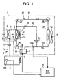
- a vehicle air conditioner 1 includes an air conditioner control unit ECU 10.
- the air conditioner 1 includes an air conditioning duct 2 forming an air passage 11 for guiding conditioned air into the interior of a vehicle.
- an outside air suction port At an air downstream side of the air conditioning duct 2, an outside air suction port, an inside air suction port and an inside/outside air switching door (not shown) are provided.
- a centrifugal blower 3 and blow ports At an air upstream side, a centrifugal blower 3 and blow ports, such as a defroster blow port, a face blow port and a foot blow port, and a mode switching door (not shown) are provided.
- the centrifugal blower 3 is composed of a scroll casing provided integrally with the air conditioning duct 2, a blower motor 12 controlled by a blower driving circuit (not shown), and a centrifugal fan 13 rotatably driven by the blower motor 12 and having a blowing capacity that may be controlled in a continuous or stepwise manner.
- a hot-water heater 5 of a hot-water warming unit 4 re-heats air that has passed through an evaporator 6.
- the hot-water heater 5 is disposed at a middle location in a cooling water circuit 14, through which a water pump (not shown) driven by a vehicle engine E circulates cooling water. If a hot-water valve 15 disposed in the cooling water circuit 14 is opened, the hot-water heater 5 causes the cooling water, having absorbed the engine exhaust heat of the engine E, to circulate therethrough. As a result, the air is re-heated so that the cooling water becomes a heat source. In other words, it acts as a downstream side, or second, heat exchanger for heating air.
- the hot-water warming unit 4 is composed of the engine E, the hot-water heater 5, the cooling water circuit 14, and the hot-water valve 15.
- the refrigerating cycle unit 20 also includes a first refrigerant circuit 21, a second refrigerant circuit 22, and first and second electromagnetic valves 23, 24 for switching the first and second refrigerant circuits 21, 22.
- the first refrigerant circuit 21 is for circulating a high temperature/high pressure gas refrigerant discharged from a compressor 7 in the following order: first electromagnetic valve 23; condenser 25; receiver 26; expansion valve 27; evaporator 6; accumulator 28; and compressor 7.
- the second refrigerant circuit 22 is for circulating a high temperature/high pressure gas refrigerant discharged from the compressor 7 in the following order: second electromagnetic valve 24; pressure reducing unit; 29; evaporator 6; accumulator 28; and compressor 7.
- the refrigerating cycle unit 20 causes the refrigerant to circulate through the first refrigerant circuit 21. Further, if the first electromagnetic valve 23 is closed and the second electromagnetic valve 24 is opened, the refrigerating cycle unit 20 causes the refrigerant to circulate through the second refrigerant circuit 22.
- the circuit switch includes the first and second electromagnetic valves 23, 24.
- numeral 16 denotes a cooling fan rotatably driven by a drive motor 17 that forcibly blows outside air to the condenser 25.
- the evaporator 6 corresponds to an internal heat exchanger.
- the evaporator causes a low temperature vapor/liquid two-phase refrigerant flowing into the circuit 21 from the expansion valve 27 to evaporate.
- the evaporator 6 functions as a cooling heat exchanger for cooling the air passing through it.
- the evaporator 6 when the refrigerant flows through the second refrigerant circuit 22, the evaporator 6 functions as a first heating heat exchanger for heating the air passing through it by passing a high temperature gas refrigerant flowing into it from the pressure reducing unit 29.
- the expansion valve 27 not only causes the refrigerant to adibiatically expand but also adjusts a circulation amount of the refrigerant in compliance with a refrigerant overheat degree of an evaporator outlet.
- the compressor 7 is preferably an engine-driven piston-type fixed volume compressor which compresses the refrigerant sucked from its suction port and discharges a high temperature/high pressure gas refrigerant from its discharge port.
- An electromagnetic clutch 8 for transmitting or interrupting rotary power of the engine E to or from the compressor 7 is connected to a shaft of the compressor 7. Further, a belt V is rotated both by a pulley 33 of the electromagnetic clutch 8 and a crank pulley of the engine E, thereby facilitating transmission of the engine rotary power to the compressor 7.
- the electromagnetic clutch 8 When the electromagnetic clutch 8 is energized (ON), the engine rotary power is transmitted to the compressor 7 via the belt V and the electromagnetic clutch 8. The refrigerating cycle unit 20 is started, and thus an air cooling action or an air heating action is performed by the evaporator 6. Further, when the electromagnetic clutch 8 is de-energized (OFF), the rotary power of the engine E is not transmitted to the compressor 7, and the air cooling or heating action is stopped.
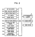
- Respective switch signals from respective switches on an air conditioning operation panel (not shown) provided in the vehicle passenger compartment are input to the air conditioning ECU 10.
- a hot gas switch (S/W) 99 a mode switching switch 100 for switching an air conditioning mode to a cooler mode or a heater mode, a temperature-setting switch 101 for setting a vehicle interior temperature to a desired temperature, an air conditioning switch 102 for starting or stopping the refrigerating cycle unit 20, a blower switch 103 for turning the centrifugal blower 3 ON/OFF, and the like are provided on the air conditioning operation panel.
- a known microcomputer including a CPU, ROM, RAM and the like is provided, and respective sensor signals from respective sensors are input to the microcomputer after being A/D-converted by an input circuit (not shown). It should be appreciated that the air conditioning ECU 10 is programmed so that, when an ignition switch of the engine E is turned on (IG ⁇ ON), control processing is started.
- respective sensor signals from an inside air temperature sensor 104 for detecting a vehicle interior air temperature, an outside air temperature sensor 105 for detecting a vehicle external air temperature, and a solar energy sensor 106 for detecting an amount of solar energy coming into the vehicle interior are input to the ECU 10.
- respective sensor signals from a post-evaporator temperature sensor 107 for detecting the temperature of air just after having passed the evaporator 6, a cooling water temperature sensor 108 for detecting the temperature of cooling water flowing into the hot-water heater 5, and a refrigerant pressure sensor 109 for detecting a high pressure (PD) of the refrigerating cycle unit 20 are also input into the ECU 10.
- the respective switches and sensors detect air conditioning environmental factors required for air-conditioning the vehicle interior, and thermistors are preferably used for the inside air temperature sensor 104, the outside air temperature sensor 105, the post-evaporator temperature sensor 107, and the cooling water temperature sensor 108.
- the air conditioning ECU 10 has a revolution speed detector which inputs an engine revolution speed sensor signal (not shown) and thereby operates the compressor revolution speed.
- step S1 the respective signals are read from the respective switches on the air conditioning operation panel. More particularly, an ON or OFF signal of the hot gas S/W 99 and a set state (cooler mode or heater mode) of the mode switching switch 100 are read.
- step S2 the respective sensor signals are read (step S2). More specifically, an outside air temperature (TAM) detected by the outside air temperature sensor 105, a cooling water temperature (TW) detected by the cooling water temperature sensor 108, and a discharge pressure (PD) of the compressor 7 detected by the refrigerant pressure sensor 109 are read. Further, based on an engine revolution speed input from the engine revolution speed sensor, a revolution speed (NC) of the compressor 7 is computed and read.
- TAM outside air temperature
- TW cooling water temperature
- PD discharge pressure
- NC revolution speed
- step S3 it is determined whether the air conditioning mode is a heater mode. That is, it is determined whether a heater mode is set by the mode switching switch 100 (step S3).
- the electromagnetic clutch (Mg/Cl) 8 is energized (ON) to thereby start the compressor 7, the first electromagnetic valve 23 is opened, the second electromagnetic valve 24 is closed, and the refrigerating cycle unit 20 is operated by the first refrigerant circuit 21 (step S4). Thereafter, the routine of Fig. 3 is exited.
- step S3 determines whether the hot gas switch 99 is turned on (ON) (step S5).
- step S5 determines whether the hot gas switch 99 is turned on (ON) (step S5).
- step S5 determines whether the hot gas switch 99 is turned on (ON) (step S5).
- step S5 determines whether the hot gas switch 99 is turned on (ON) (step S5).
- step S5 determines whether the hot gas switch 99 is turned on (ON) (step S5).
- the electromagnetic clutch (Mg/Cl) 8 is de-energized (OFF) to thereby automatically stop the compressor 7, and the first and second electromagnetic valves 23, 24 are closed (step S6). Thereafter, the routine is exited.
- step S5 when a result of the determination at step S5 is YES, i.e., when the hot gas switch is ON, it is determined whether the cooling water temperature (TW) is equal to or less than a predetermined temperature (for example 80°C) (step S7). When the determination is NO, control processing proceeds to step S6.
- TW cooling water temperature
- a suction pressure (PS) of the compressor 7 is computed. More specifically, the suction pressure (PS) of the compressor 7 is presumed from a revolution speed (NC) of the compressor 7 computed based on a sensor signal from the engine revolution speed sensor, and from an outside air temperature (TAM) detected by the outside air temperature sensor 105 (step S8).
- NC revolution speed
- TAM outside air temperature
- a possible starting region is determined, within which if the compressor 7 is started, a suction portion of the compressor 7 at a positive pressure so that air penetration through shaft seal portion of the compressor 7 is inhibited (step S9).
- step S8 it is determined whether the suction pressure (PS) of the compressor 7 determined at step S8 is equal to or higher than a predetermined value (for example -0.5 kg/cm 2 G). More particularly, it is determined whether the outside air temperature (TAM) or the revolution speed (NC) of the compressor 7 is within the possible starting region of the compressor 7 (step S10). When a result of this determination is NO, processing proceeds to step S6.
- a predetermined value for example -0.5 kg/cm 2 G
- step S10 when a result of the determination at step S10 is YES, the electromagnetic clutch (Mg/Cl) 8 is energized (ON) to thereby (re-)start the compressor 7, the first electromagnetic valve 23 is closed, the second electromagnetic valve 24 is opened, and thus the refrigerating cycle unit 20 is operated by the second refrigerant circuit 22 (step S11). Thereafter, the routine of Fig. 3 is exited.
- the electromagnetic clutch 8 When the air conditioning mode is a cooler mode, the electromagnetic clutch 8 is ON, the first electromagnetic valve 23 is opened, and the second electromagnetic valve 24 is closed. Therefore, a high temperature/high pressure gas refrigerant discharged from the compressor 7 circulates through the first refrigerant circuit 21 and flows into the evaporator 6. The air sucked into the air conditioning duct 2 is cooled by being heat-exchanged with a low temperature/low pressure refrigerant in the evaporator 6, and is blown into a vehicle interior. As a result, the vehicle interior is cooled.
- the hot gas switch 99 When the air conditioning mode is a heater mode, the hot gas switch 99 is ON.
- the cooling water temperature (TW) is equal to or lower than a predetermined temperature (for example 80°C) and thus the hot-water warming unit 4 cannot heat the vehicle interior sufficiently and it is within a possible starting region of the compressor 7, the electromagnetic clutch 8 is turned ON, the first electromagnetic valve 23 is closed and the second electromagnetic valve 24 is opened. Further, the hot-water valve 15 is opened as well.
- the high temperature/high pressure gas refrigerant discharged from the compressor 7 circulates through the second refrigerant circuit 22 and flows into the evaporator 6. Further, the cooling water, having absorbed the exhaust heat of the engine E, circulates through the cooling water circuit 14 and flows into the hot-water heater 5. The air sucked into the air conditioning duct 2 is heated by being heat-exchanged with a high temperature/low pressure refrigerant in the evaporator 6 and is further heated by being heat-exchanged with a high temperature cooling water in the hot-water heater 5 and blown into a vehicle interior. As a result, the vehicle interior is warmed.
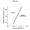
- the possible compressor starting region in this embodiment is decided by determining the suction pressure (PS) of the compressor 7 from, for example, the revolution speed (NC) of the compressor 7 and the outside air temperature (TAM).
- PS suction pressure
- N revolution speed
- TAM outside air temperature
- the suction pressure (PS) of the compressor 7 is a predetermined value (for example -0.5 kg/cm 2 G). Therefore, if the revolution speed of the compressor 7 is 1000 rpm and the outside air temperature is lower than -30°C, or if the outside air temperature is -30°C and the revolution speed of the compressor 7 is higher than 1000 rpm, the compressor is automatically stopped (caused not to start), as the probability that a suction portion of the compressor 7 is at a negative pressure when starting the compressor 7 is high.
- PS suction pressure
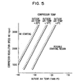
- the suction pressure (PS) of the compressor 7 is a predetermined value (for example -0.5 kg/cm 2 G). Therefore, if the compressor 7 is operating at 3000 rpm and the outside air temperature is lower than -20°C, or if the outside air temperature is -20°C and the speed of the compressor 7 is higher than 3000 rpm, the compressor is automatically stopped (caused not to start), as the probability that a suction portion of the compressor 7 is at a negative pressure during startup is high.
- the suction pressure of the compressor 7 is prevented from decreasing just after the compressor 7 is started by automatically stopping the compressor 7 to thereby stop an auxiliary warming operation, so that a negative pressure condition at the suction portion of the compressor 7 can be prevented.
- Fig. 5 shows a second embodiment of the present invention.
- the suction pressure (PS) of the compressor 7 is determined as in the first embodiment.
- the compressor 7 may be more easily started as the temperature of the compressor increases.
- Fig. 6 shows a third embodiment of the present invention.
- control states identical to those in the flow diagram of Fig. 3 are denoted with identical numerals, and the corresponding description is omitted.
- a sensor signal from a not-shown refrigerant pressure switch (or refrigerant pressure sensor) is input to the air conditioning ECU 10. Therefore, it is possible to detect the suction pressure (PS) of the compressor 7.
- step S22 determines whether a result of the determination at step S22 is NO.
- TW cooling water temperature
- step S25 a predetermined temperature (for example 80°C)
- step S25 when the determination at step S25 is YES, the electromagnetic clutch (Mg/Cl) 8 is energized (ON) to thereby (re-)start the compressor 7, the first electromagnetic valve 23 is closed, the second electromagnetic valve 24 is opened, and thus the refrigerating cycle unit 20 is operated by the second refrigerant circuit 22 (step S26).
- step S27 it is determined whether the suction pressure (PS) of the compressor 7 detected by the pressure switch (or pressure sensor) is lower than a predetermined value (for example -0.5 kg/cm 2 G) (step S27). When this determination is NO, processing returns to step S22.
- a predetermined value for example -0.5 kg/cm 2 G
- the suction pressure (PS) of the compressor 7 is directly detected by the refrigerant pressure switch (or refrigerant pressure sensor).
- the detected suction pressure (PS) is lower than a predetermined value (for example -0.5 kg/cm 2 G)
- the electromagnetic clutch 8 is turned OFF to thereby automatically stop the compressor 7 (hot gas heater cycle).
- a predetermined time for example 60 seconds
- the electromagnetic clutch 8 is turned ON to thereby re-start the compressor 7.
- the hot gas heater cycle can be re-started after a predetermined time has elapsed from when the hot gas cycle is automatically stopped, when the hot-water heater 5 of the hot-water warming unit 4 utilizing the cooling water of the engine provides insufficient heating, the hot-water heater 5 is assisted by hot gas guided to the evaporator 6, so that the vehicle interior can be rapidly warmed after the hot-water warming unit 4 is started.
- the invention has been applied to a vehicle air conditioner refrigerating cycle apparatus, it may also be applied to the air conditioner refrigerating cycle apparatus of an airplane, a ship, a railway vehicle, and the like. Further, the invention may be applied to the air conditioner refrigerating cycle apparatus of a factory, a shop, a house, and the like.
Landscapes
- Physics & Mathematics (AREA)
- Thermal Sciences (AREA)
- Engineering & Computer Science (AREA)
- Mechanical Engineering (AREA)
- Air-Conditioning For Vehicles (AREA)
Claims (18)
- Dispositif à cycle frigorifique comprenant :caractérisé en ce queun premier circuit de réfrigérant (21) comprenant respectivement un compresseur de réfrigérant (7) destiné à refouler un réfrigérant à haute température, un échangeur de chaleur externe (25) destiné à recevoir le réfrigérant refoulé, un premier moyen de réduction de pression (27) et un échangeur de chaleur interne (6) destiné à refroidir l'air avant que le réfrigérant ne soit retourné vers le compresseur de réfrigérant (7),un second circuit de réfrigérant (22) comprenant respectivement un second moyen de réduction de pression (29) et l'échangeur de chaleur interne (6) destiné à réchauffer l'air conditionné avant que le réfrigérant ne soit retourné vers le compresseur de réfrigérant (7), le second circuit de réfrigérant (22) contournant l'échangeur de chaleur externe (25), etun moyen de commande de conditionnement d'air (10) destiné à commander le compresseur de réfrigérant (7),
un moyen de détection de pression d'aspiration destiné à détecter une quantité physique représentative d'une pression d'aspiration du compresseur de réfrigérant (7) est prévu et en ce que
le second circuit de réfrigérant (22) est automatiquement stoppé par ledit moyen de commande de conditionnement d'air (10) destiné à commander le compresseur de réfrigérant (7), lorsque la quantité physique détectée par le moyen de détection de pression d'aspiration est inférieure à une valeur prédéterminée. - Dispositif à cycle frigorifique selon la revendication 1, dans lequel le moyen de commande de conditionnement d'air (10) commande le compresseur de réfrigérant (7) de sorte que le second circuit de réfrigérant (22) soit redémarré après un temps écoulé prédéterminé, après avoir été automatiquement stoppé.
- Dispositif à cycle frigorifique selon la revendication 1, dans lequel le moyen de détection de pression d'aspiration comprend un moyen de détection de température d'air extérieur (150) destiné à détecter une température de l'air extérieur et un moyen de détection de vitesse de rotation (110) destiné à détecter une vitesse de rotation du compresseur de réfrigérant (7), et
le moyen de détection de pression d'aspiration détermine la pression d'aspiration du compresseur de réfrigérant (7) sur la base de la température de l'air extérieur détectée et de la vitesse du compresseur détectée, établit une région de démarrage possible du compresseur de réfrigérant (7) sur la base de la pression d'aspiration déterminée et commande le compresseur de réfrigérant (7) de sorte que le second circuit de réfrigérant (22) soit démarré uniquement dans la région de démarrage possible. - Dispositif à cycle frigorifique selon la revendication 3,
dans lequel le moyen de détection de pression d'aspiration corrige la région de démarrage possible sur la base d'une quantité physique représentant une température du compresseur de réfrigérant (7). - Dispositif à cycle frigorifique selon la revendication 4,
dans lequel la quantité physique représentant la température du compresseur (7) est choisie parmi le groupe constitué de : une température d'eau de refroidissement du moteur, une température d'huile de lubrification du moteur et une pression du réfrigérant dans les premier et second circuits de réfrigérant. - Dispositif à cycle frigorifique comprenant :caractérisé en ce queun premier circuit de réfrigérant (21) comprenant un compresseur de réfrigérant (7) et un échangeur de chaleur interne (6) destiné à refroidir l'air avant que le réfrigérant ne soit retourné vers le compresseur de réfrigérant (7),un second circuit de réfrigérant (22) comprenant respectivement l'échangeur de chaleur interne (6) destiné à réchauffer l'air conditionné avant que le réfrigérant ne soit retourné vers le compresseur de réfrigérant (7), etun contrôleur de compresseur (10) destiné à commander sélectivement le fonctionnement des premier et second circuits de réfrigérant (21, 22),
un détecteur de pression d'aspiration est prévu en vue de détecter une quantité physique représentative d'une pression d'aspiration du compresseur de réfrigérant (7)
dans lequel le contrôleur de compresseur (10) commande le fonctionnement des premier et second circuits de réfrigérant (21, 22) sur la base de la quantité physique détectée par le détecteur de pression d'aspiration, et
un circuit d'eau de refroidissement (4) est prévu en vue de réchauffer l'air avec l'eau de refroidissement du moteur chauffée, dans lequel le contrôleur (10) active le second circuit de réfrigérant (22) lorsque la température de l'eau de refroidissement dans le circuit d'eau de refroidissement (4) est au-dessous d'une valeur prédéterminée dans un mode de réchauffage de l'air. - Dispositif à cycle frigorifique selon la revendication 6,
dans lequel le premier circuit de réfrigérant (21) comprend un échangeur de chaleur externe (25) et le second circuit de réfrigérant (22) contourne l'échangeur de chaleur externe (25). - Dispositif à cycle frigorifique selon la revendication 6, comprenant en outre un circuit de commutation (23, 24) commandé par le contrôleur (10) en vue de commuter le fonctionnement des premier et second circuits de réfrigérant (21, 22).
- Dispositif à cycle frigorifique selon la revendication 6,
dans lequel le contrôleur (10) active le second circuit de réfrigérant (22) uniquement lorsqu'une région de démarrage possible du compresseur existe. - Dispositif à cycle frigorifique selon la revendication 9, dans lequel la région de démarrage possible du compresseur existe lorsqu'une pression d'aspiration du compresseur chute à l'intérieur d'une plage prédéterminée.
- Dispositif à cycle frigorifique selon la revendication 10, dans lequel la région de démarrage possible du compresseur est corrigée sur la base de l'une d'une température du compresseur et d'une quantité physique correspondant à la température du compresseur.
- Dispositif à cycle frigorifique selon la revendication 6, dans lequel le contrôleur de compresseur (10) commande sélectivement le fonctionnement des premier et second circuits de réfrigérant (21, 22) sur la base de la pression d'aspiration du compresseur détectée directement par le détecteur de pression d'aspiration.
- Dispositif à cycle frigorifique selon la revendication 12, dans lequel le contrôleur (10) arrête automatiquement le compresseur (7) et les premier et second circuits de réfrigérant (21, 22) pendant un temps prédéterminé lorsque la pression d'aspiration est au-dessous d'un niveau prédéterminé.
- Procédé de commande du fonctionnement d'un circuit de réchauffage d'air auxiliaire (22) dans un système de conditionnement d'air de véhicule (1) comprenant un circuit de réchauffage d'air principal (4) et le circuit de réchauffage d'air auxiliaire (22), dans lequel le circuit de réchauffage d'air auxiliaire (22) fait circuler un réfrigérant refoulé d'un compresseur (7), caractérisé par les étapes consistant à
surveiller un mode de fonctionnement du système (S1 à S5),
déterminer une température de l'eau de refroidissement du moteur circulant dans le circuit de réchauffage d'air principal lorsque l'étape de surveillance indique que le mode de fonctionnement du système est dans un mode de réchauffage (S7),
déterminer si les paramètres de fonctionnement du compresseur du circuit de réchauffage d'air auxiliaire s'inscrivent à l'intérieur d'une plage de démarrage de compresseur prédéterminée (S8 à S10), et
démarrer le compresseur du circuit de réchauffage d'air auxiliaire lorsque les paramètres de fonctionnement du compresseur s'inscrivent à l'intérieur de la plage de démarrage du compresseur prédéterminée (S11). - Procédé selon la revendication 14, dans lequel l'étape consistant à déterminer si une pression d'aspiration du compresseur du circuit de réchauffage d'air auxiliaire s'inscrit à l'intérieur d'une plage de démarrage de compresseur prédéterminée comprend :la mesure de la température de l'air extérieur et de la vitesse de rotation du compresseur, etl'estimation de la pression d'aspiration du compresseur à partir de la température de l'air extérieur et de la vitesse de rotation du compresseur.
- Procédé selon la revendication 15, comprenant en outre l'étape consistant à corriger la plage de démarrage du compresseur prédéterminée sur la base de l'une d'une température du compresseur et d'une quantité physique correspondant à la température du compresseur.
- Procédé selon la revendication 14, comprenant en outre l'étape consistant à mesurer directement la pression d'aspiration du compresseur avant l'étape consistant à déterminer si une pression d'aspiration du compresseur du circuit de réchauffage d'air auxiliaire s'inscrit à l'intérieur d'une plage de démarrage de compresseur prédéterminée (S27).
- Procédé selon la revendication 17, comprenant en outre l'arrêt du compresseur et du circuit de réfrigérant auxiliaire pendant une durée prédéterminée lorsque la pression d'aspiration se situe au-dessous d'un niveau prédéterminé (S28).
Applications Claiming Priority (2)
| Application Number | Priority Date | Filing Date | Title |
|---|---|---|---|
| JP31786098A JP4003320B2 (ja) | 1998-11-09 | 1998-11-09 | 冷凍サイクル装置 |
| JP31786098 | 1998-11-09 |
Publications (3)
| Publication Number | Publication Date |
|---|---|
| EP1000787A2 EP1000787A2 (fr) | 2000-05-17 |
| EP1000787A3 EP1000787A3 (fr) | 2002-06-19 |
| EP1000787B1 true EP1000787B1 (fr) | 2003-10-08 |
Family
ID=18092877
Family Applications (1)
| Application Number | Title | Priority Date | Filing Date |
|---|---|---|---|
| EP99120937A Expired - Lifetime EP1000787B1 (fr) | 1998-11-09 | 1999-11-02 | Appareil de climatisation du type pompe à chaleur pour véhicule et procédé d'inhibition de la corrosion et pour faciliter le chauffage rapide de l'habitacle pendant de basses températures |
Country Status (4)
| Country | Link |
|---|---|
| US (1) | US6237681B1 (fr) |
| EP (1) | EP1000787B1 (fr) |
| JP (1) | JP4003320B2 (fr) |
| DE (1) | DE69911885T2 (fr) |
Cited By (1)
| Publication number | Priority date | Publication date | Assignee | Title |
|---|---|---|---|---|
| DE10332157A1 (de) * | 2003-06-26 | 2005-01-13 | Behr Gmbh & Co. Kg | Einrichtung zum Kühlen oder zum Erwärmen eines geschlossenen Raumes sowie Verfahren zum Betrieb einer solchen Einrichtung |
Families Citing this family (24)
| Publication number | Priority date | Publication date | Assignee | Title |
|---|---|---|---|---|
| CN1133047C (zh) * | 2001-03-14 | 2003-12-31 | 清华同方股份有限公司 | 一种适用于寒冷地区的热泵空调机组 |
| JP4661011B2 (ja) * | 2001-09-10 | 2011-03-30 | 株式会社デンソー | 車両用空調装置 |
| JP4085694B2 (ja) * | 2002-02-27 | 2008-05-14 | 株式会社デンソー | 空気調和装置 |
| US7207379B2 (en) | 2002-03-18 | 2007-04-24 | Denso Corporation | Automotive air conditioning system |
| JP3990593B2 (ja) * | 2002-05-09 | 2007-10-17 | 本田技研工業株式会社 | 車両用ヒートポンプ式空調装置 |
| KR100917173B1 (ko) | 2003-01-29 | 2009-09-15 | 한라공조주식회사 | 차량용 냉난방 시스템 |
| JP2004338447A (ja) * | 2003-05-13 | 2004-12-02 | Denso Corp | 空調装置 |
| US7178353B2 (en) * | 2004-02-19 | 2007-02-20 | Advanced Thermal Sciences Corp. | Thermal control system and method |
| JP2005351286A (ja) * | 2004-06-08 | 2005-12-22 | Shin Caterpillar Mitsubishi Ltd | 入出力回転数比可変型クラッチの制御装置 |
| JP3891196B2 (ja) * | 2004-11-25 | 2007-03-14 | ダイキン工業株式会社 | 冷凍装置 |
| JP4380730B2 (ja) | 2007-05-28 | 2009-12-09 | 株式会社デンソー | 冷凍サイクル装置のコンプレッサの吸入圧力推定装置 |
| JP4375437B2 (ja) | 2007-05-28 | 2009-12-02 | 株式会社デンソー | 冷凍サイクル装置のコンプレッサの吸入圧力推定装置 |
| US20170080773A1 (en) | 2008-11-03 | 2017-03-23 | Arkema France | Vehicle Heating and/or Air Conditioning Method |
| FR2937906B1 (fr) * | 2008-11-03 | 2010-11-19 | Arkema France | Procede de chauffage et/ou climatisation d'un vehicule. |
| US9453669B2 (en) * | 2009-12-08 | 2016-09-27 | Thermo King Corporation | Method of controlling inlet pressure of a refrigerant compressor |
| JP5851703B2 (ja) * | 2011-02-25 | 2016-02-03 | サンデンホールディングス株式会社 | 車両用空気調和装置 |
| JP5851696B2 (ja) * | 2011-01-21 | 2016-02-03 | サンデンホールディングス株式会社 | 車両用空気調和装置 |
| US9925877B2 (en) | 2011-01-21 | 2018-03-27 | Sanden Holdings Corporation | Vehicle air conditioning apparatus |
| DE112012000522B4 (de) | 2011-01-21 | 2020-12-17 | Sanden Holdings Corporation | Fahrzeugklimatisierungseinrichtung |
| WO2015011920A1 (fr) | 2013-07-26 | 2015-01-29 | パナソニックIpマネジメント株式会社 | Dispositif de climatisation pour véhicule |
| KR101575317B1 (ko) * | 2014-05-27 | 2015-12-07 | 현대자동차 주식회사 | 차량 공기 유량 제어 시스템 및 그 제어 방법 |
| US10041552B2 (en) * | 2015-07-16 | 2018-08-07 | Ford Global Technologies, Llc | Methods and systems for controlling a vehicle air conditioner using a pressure sensor located within a compressor |
| CN105352212B (zh) * | 2015-11-30 | 2018-05-22 | 江苏博莱客冷冻科技发展有限公司 | 一种低温空气连续发生装置和制备方法 |
| JP7505452B2 (ja) * | 2021-06-21 | 2024-06-25 | トヨタ自動車株式会社 | 電池冷却装置 |
Family Cites Families (8)
| Publication number | Priority date | Publication date | Assignee | Title |
|---|---|---|---|---|
| US2363273A (en) * | 1943-06-02 | 1944-11-21 | Buensod Stacey Inc | Refrigeration |
| JPH04124479A (ja) * | 1990-09-13 | 1992-04-24 | Toyota Autom Loom Works Ltd | 圧縮機 |
| JP3237187B2 (ja) | 1991-06-24 | 2001-12-10 | 株式会社デンソー | 空調装置 |
| GB2272506B (en) * | 1992-11-02 | 1996-07-24 | Nippon Denso Co | Refrigerant condenser |
| JPH1076841A (ja) * | 1996-09-06 | 1998-03-24 | Calsonic Corp | ヒートポンプ式自動車用空気調和装置 |
| EP0842799A3 (fr) * | 1996-11-15 | 2003-03-05 | Calsonic Kansei Corporation | Appareil de climatisation du type pompe à chaleur pour véhicule automobile. |
| US6076366A (en) * | 1998-04-03 | 2000-06-20 | Denso Corporation | Refrigerating cycle system with hot-gas bypass passage |
| JP3386014B2 (ja) * | 1998-11-25 | 2003-03-10 | 株式会社デンソー | 冷凍サイクル装置 |
-
1998
- 1998-11-09 JP JP31786098A patent/JP4003320B2/ja not_active Expired - Fee Related
-
1999
- 1999-10-25 US US09/427,395 patent/US6237681B1/en not_active Expired - Lifetime
- 1999-11-02 EP EP99120937A patent/EP1000787B1/fr not_active Expired - Lifetime
- 1999-11-02 DE DE69911885T patent/DE69911885T2/de not_active Expired - Lifetime
Cited By (1)
| Publication number | Priority date | Publication date | Assignee | Title |
|---|---|---|---|---|
| DE10332157A1 (de) * | 2003-06-26 | 2005-01-13 | Behr Gmbh & Co. Kg | Einrichtung zum Kühlen oder zum Erwärmen eines geschlossenen Raumes sowie Verfahren zum Betrieb einer solchen Einrichtung |
Also Published As
| Publication number | Publication date |
|---|---|
| JP2000142094A (ja) | 2000-05-23 |
| US6237681B1 (en) | 2001-05-29 |
| EP1000787A3 (fr) | 2002-06-19 |
| DE69911885T2 (de) | 2004-05-19 |
| DE69911885D1 (de) | 2003-11-13 |
| JP4003320B2 (ja) | 2007-11-07 |
| EP1000787A2 (fr) | 2000-05-17 |
Similar Documents
| Publication | Publication Date | Title |
|---|---|---|
| EP1000787B1 (fr) | Appareil de climatisation du type pompe à chaleur pour véhicule et procédé d'inhibition de la corrosion et pour faciliter le chauffage rapide de l'habitacle pendant de basses températures | |
| US7398653B2 (en) | Air conditioner for vehicle capable of preventing inverter overheating | |
| US20050210897A1 (en) | Vehicular air-conditioner | |
| US7207379B2 (en) | Automotive air conditioning system | |
| US5918475A (en) | Air conditioning apparatus for vehicle, using a flammable refrigerant | |
| US5701753A (en) | Air conditioning apparatus | |
| US6082626A (en) | Cooling water circuit system | |
| US20030037562A1 (en) | Vehicle air conditioner with defrosting operation in exterior heat exchanger | |
| US6931873B2 (en) | Vehicle air conditioner | |
| JPH07294071A (ja) | 自動車用空気調和装置 | |
| JP2001063348A (ja) | 冷凍サイクル装置 | |
| US20030046946A1 (en) | Vehicle air-conditioning system | |
| US5769316A (en) | Air conditioner for vehicles | |
| US6725676B2 (en) | Refrigerant cycle system with hot gas heating function | |
| JP3794115B2 (ja) | 空気調和装置 | |
| JP3617143B2 (ja) | 車両用空調装置 | |
| GB2395776A (en) | Vehicle air conditioner having a refrigerant cycle with heating function | |
| JP2004182165A (ja) | 車両用空調装置 | |
| JP3858738B2 (ja) | 車両用空気調和装置 | |
| JPH1142934A (ja) | 空気調和装置 | |
| JPH10160301A (ja) | 車両用空調装置 | |
| KR100928000B1 (ko) | 자동차용 공기조화장치의 난방 제어방법 | |
| JP2541843B2 (ja) | 自動車用空調装置 | |
| JP2000225837A (ja) | 車両用空調装置 | |
| JP3690008B2 (ja) | 車両用外気温検出装置 |
Legal Events
| Date | Code | Title | Description |
|---|---|---|---|
| PUAI | Public reference made under article 153(3) epc to a published international application that has entered the european phase |
Free format text: ORIGINAL CODE: 0009012 |
|
| AK | Designated contracting states |
Kind code of ref document: A2 Designated state(s): AT BE CH CY DE DK ES FI FR GB GR IE IT LI LU MC NL PT SE |
|
| AX | Request for extension of the european patent |
Free format text: AL;LT;LV;MK;RO;SI |
|
| PUAL | Search report despatched |
Free format text: ORIGINAL CODE: 0009013 |
|
| AK | Designated contracting states |
Kind code of ref document: A3 Designated state(s): AT BE CH CY DE DK ES FI FR GB GR IE IT LI LU MC NL PT SE |
|
| AX | Request for extension of the european patent |
Free format text: AL;LT;LV;MK;RO;SI |
|
| RIC1 | Information provided on ipc code assigned before grant |
Free format text: 7B 60H 1/32 A, 7B 60H 1/00 B, 7F 25B 41/04 B |
|
| 17P | Request for examination filed |
Effective date: 20020801 |
|
| 17Q | First examination report despatched |
Effective date: 20021002 |
|
| AKX | Designation fees paid |
Designated state(s): DE FR GB IT |
|
| GRAH | Despatch of communication of intention to grant a patent |
Free format text: ORIGINAL CODE: EPIDOS IGRA |
|
| GRAS | Grant fee paid |
Free format text: ORIGINAL CODE: EPIDOSNIGR3 |
|
| GRAA | (expected) grant |
Free format text: ORIGINAL CODE: 0009210 |
|
| AK | Designated contracting states |
Kind code of ref document: B1 Designated state(s): DE FR GB IT |
|
| REG | Reference to a national code |
Ref country code: GB Ref legal event code: FG4D |
|
| REG | Reference to a national code |
Ref country code: IE Ref legal event code: FG4D |
|
| REF | Corresponds to: |
Ref document number: 69911885 Country of ref document: DE Date of ref document: 20031113 Kind code of ref document: P |
|
| ET | Fr: translation filed | ||
| PLBE | No opposition filed within time limit |
Free format text: ORIGINAL CODE: 0009261 |
|
| STAA | Information on the status of an ep patent application or granted ep patent |
Free format text: STATUS: NO OPPOSITION FILED WITHIN TIME LIMIT |
|
| REG | Reference to a national code |
Ref country code: IE Ref legal event code: MM4A |
|
| 26N | No opposition filed |
Effective date: 20040709 |
|
| REG | Reference to a national code |
Ref country code: GB Ref legal event code: 746 Effective date: 20050210 |
|
| PGFP | Annual fee paid to national office [announced via postgrant information from national office to epo] |
Ref country code: GB Payment date: 20091028 Year of fee payment: 11 Ref country code: FR Payment date: 20091123 Year of fee payment: 11 |
|
| PGFP | Annual fee paid to national office [announced via postgrant information from national office to epo] |
Ref country code: IT Payment date: 20091113 Year of fee payment: 11 |
|
| GBPC | Gb: european patent ceased through non-payment of renewal fee |
Effective date: 20101102 |
|
| REG | Reference to a national code |
Ref country code: FR Ref legal event code: ST Effective date: 20110801 |
|
| PG25 | Lapsed in a contracting state [announced via postgrant information from national office to epo] |
Ref country code: FR Free format text: LAPSE BECAUSE OF NON-PAYMENT OF DUE FEES Effective date: 20101130 |
|
| PG25 | Lapsed in a contracting state [announced via postgrant information from national office to epo] |
Ref country code: GB Free format text: LAPSE BECAUSE OF NON-PAYMENT OF DUE FEES Effective date: 20101102 |
|
| PG25 | Lapsed in a contracting state [announced via postgrant information from national office to epo] |
Ref country code: IT Free format text: LAPSE BECAUSE OF NON-PAYMENT OF DUE FEES Effective date: 20101102 |
|
| PGFP | Annual fee paid to national office [announced via postgrant information from national office to epo] |
Ref country code: DE Payment date: 20121031 Year of fee payment: 14 |
|
| REG | Reference to a national code |
Ref country code: DE Ref legal event code: R119 Ref document number: 69911885 Country of ref document: DE Effective date: 20140603 |
|
| PG25 | Lapsed in a contracting state [announced via postgrant information from national office to epo] |
Ref country code: DE Free format text: LAPSE BECAUSE OF NON-PAYMENT OF DUE FEES Effective date: 20140603 |