EP1001277B1 - Appareil personnel et réutilisable de surveillance de radiation et procédé de détermination de la quantité de radiation à partir de mesures faires avec l'appareil - Google Patents
Appareil personnel et réutilisable de surveillance de radiation et procédé de détermination de la quantité de radiation à partir de mesures faires avec l'appareil Download PDFInfo
- Publication number
- EP1001277B1 EP1001277B1 EP19990203167 EP99203167A EP1001277B1 EP 1001277 B1 EP1001277 B1 EP 1001277B1 EP 19990203167 EP19990203167 EP 19990203167 EP 99203167 A EP99203167 A EP 99203167A EP 1001277 B1 EP1001277 B1 EP 1001277B1
- Authority
- EP
- European Patent Office
- Prior art keywords
- phosphor
- layer
- energy
- electroluminescent
- radiation
- Prior art date
- Legal status (The legal status is an assumption and is not a legal conclusion. Google has not performed a legal analysis and makes no representation as to the accuracy of the status listed.)
- Expired - Lifetime
Links
Images


Classifications
-
- G—PHYSICS
- G01—MEASURING; TESTING
- G01T—MEASUREMENT OF NUCLEAR OR X-RADIATION
- G01T1/00—Measuring X-radiation, gamma radiation, corpuscular radiation, or cosmic radiation
- G01T1/02—Dosimeters
- G01T1/10—Luminescent dosimeters
- G01T1/105—Read-out devices
-
- G—PHYSICS
- G01—MEASURING; TESTING
- G01T—MEASUREMENT OF NUCLEAR OR X-RADIATION
- G01T1/00—Measuring X-radiation, gamma radiation, corpuscular radiation, or cosmic radiation
- G01T1/16—Measuring radiation intensity
- G01T1/20—Measuring radiation intensity with scintillation detectors
- G01T1/2012—Measuring radiation intensity with scintillation detectors using stimulable phosphors, e.g. stimulable phosphor sheets
Definitions
- This invention relates to a reusable personal monitor in form of a handsome card providing a quantitative determination of harmful threatening ionizing irradiation.
- Dosimeters suitable to detect,and to quantify harmful or threatening ionizing irradiation are known for years. Especially people working with radioactive isotopes as in analytical research laboratories, in nuclear medical research, in nuclear power-stations and in non-destructive testing of materials should be under permanent preventive control in order to be informed about the dose of ionizing radiation to which they have been exposed within a well-known working time.
- Well-known types of dosimeters are e.g. based on CsI-crystal scintillators, mostly in form of a pencil, which provide permanent controll. When a quantified critical or treshold value becomes exceeded, a system in form of a sound alarm may warn the controlled person.
- electronic gadgets such as personal identification, personal "irradiation history", etc., have become available, even in contact with a network, in order to maximize personal security measures.
- Another detection system makes use of detectors in form of a badge which, after having been borne during a certain period of time are controlled centrally.
- Quantifying irradiation can be based on silver halide photography (as e.g. in nuclear power-stations, described as in "Gebrauchsan Anlagen für das Wunsch für das Wunschdosimeter mit Ganz stressesdosimetersonden, Typ GSF-Film-GD 10/20, GSF-Forschungs congress für processor und Pass GmbH - Institut für Strahlenschutz - Ausêtsstelle für Strahlendosimeter - Stand: 1March 1994).
- Another quantifying method can be based on thermoluminescence (e.g.
- thermoluminescence and PSL-dosimetry can be reused.
- Another detector offering the same advantage of reusability is a stimulable phosphor medium as has been disclosed in EP-A 0 844 497 and in EP-A 0 892 283.
- EP-A 0 844 497 a method has been disclosed of checking whether an article has been inspected by penetrating radiation.
- it relates to a method making it possible to check whether a piece of luggage.has been inspected by X-rays or not and to a method for personal monitoring.
- a label according to the first embodiment of this invention can beneficially be used as means for personal monitoring. When a person working in an environment with penetrating radiation carries such a label, the label can be used to determine the dose of penetrating radiation absorbed by that person.
- the amount of energy of the penetrating radiation stored in the phosphor is proportional to the absorbed dose and can be read out and the remaining amount of energy stored in the phosphor can be erased by erasing radiation. It was found that the ease of erasure was related to the energy of the penetrating radiation that irradiated the label. E.g. energy stored in the label by irradiation with Co 60 (1 MeV) radiation is less easily erased than the energy stored in the label by irradiation with penetrating radiation of 50 keV.
- the time needed to erase the amount of energy stored in the phosphor to a given level is a function of the energy of the penetrating radiation that left said amount of energy stored in the phosphor and by checking the amount of energy left in the phosphor after a given time the energy of the penetrating radiation can be determined. It is clear that for each type of storage phosphor used in the label a calibration of the readings both to determination of the amount of energy stored and to the determination of the energy of the radiation causing the amount of energy to be stored has to be performed.
- the phosphor can be calibrated so that the energy of the penetrating radiation can be assessed by reading the time needed to reach an erasure depth (erasure depth : the degree to which the amount of energy stored has been erased.).
- the invention encompasses a method for personal monitoring comprising the steps of
- a label according to the first embodiment of that invention and used for personal monitoring it is possible to incorporate different phosphors for the detection of penetrating radiation of different energy.
- a label used for personal monitoring, wherein only one type of phosphor is present with different filters so that , e.g., on one patch of the phosphor a filter letting only Co 60 radiation pass is present, on a second patch a filter letting only Ir 192 radiation pass, on a third patch a filter letting only pass X-rays with energy between 50 and 400 keV, etc.
- means for storing energy of penetrating radiation are means that convert the energy of absorbed penetrating radiation into electrons, these electrons being stored in an electronic memory that can repeatedly be read-out.
- a personal monitor comprising a storage medium for absorbing incident radiation energy, wherein said storage medium comprises a storage phosphor panel capable to store radiation energy originating from radiation having a wavelength of 350 nm or less, wherein said panel is covered with an optical filter absorbing radiation having a wavelength of 350 nm or more and wherein said panel is present in a housing, being preferably provided with a shutter element to avoid exposure at those moments when it is undesirable or irrelevant.
- said storage medium comprises a storage phosphor panel capable to store radiation energy originating from radiation having a wavelength of 350 nm or less, wherein said panel is covered with an optical filter absorbing radiation having a wavelength of 350 nm or more and wherein said panel is present in a housing, being preferably provided with a shutter element to avoid exposure at those moments when it is undesirable or irrelevant.
- said incident radiation is therein substantially composed of UV-B and UV-A rays in the wavelength range from 250 to 350 nm and said storage phosphor panel comprises storage phosphors having a dark decay of 2 hours or more as it was an object of that invention to provide a personal monitor as an indicator making it possible to check in a quantitative way any amount of harmful (sun) rays irradiating the human skin, more in particular to provide a quantitative indicator for measuring irradiation of the human skin by (over)exposure to harmful UV-A and UV-B radiation originating from sun-rays and/or solar panels and to provide a method for quantitatively checking the amount of accumulated radiation and comparing it with radiation doses tolerable within a certain exposure time as a function of age, location on earth, skin type, protection factor of sun cream used, etc.
- Said personal monitor therefore further comprises a digital memory storing medium, preferably an EPROM, a bubble memory, a non-volatile RAM or a magnetic memory.
- said stimulating energy is originated from visible light, from thermal energy or from electroluminescent energy and detecting said released energy proceeds by an optical system comprising a photomultiplier, a photodiode, a phototransistor or a gas detector. Further said optical system collimates light with optical fibres, leading it to a light detector, wherein, before entering said light detector, an optical filter is present absorbing stimulating radiation and transmitting fluorescent light.
- An apparatus for readout of storage means is also claimed wherein said apparatus comprises a DSP(digital signal processing)-chip in order to quantitatively determine energy released by said storage means.
- the objects of the present invention are realized by providing a device for recording and storing incident radiation energy and for reading said energy comprising :
- Said device is thus realized as a reusable personal monitor in form of a handsome, inexpensive card providing, after reading out the captured irradiation energy, a quantitative determination of harmful threatening ionizing irradiation as will become clear from the description and of the drawings hereinafter.
- the housing in the present invention doesn't need to be provided with additional components as e.g. shutters in order to avoid undesired exposure from e.g. daylight.
- the card is only transmitting light at the edges. Any light from the outside region of the card needs to pass the optical filter that is absorbing all stimulating wavelengths.
- the detector showing this embodiment is thereby unsensitive for daylight and therefore it does not need to be kept in the dark.
- the "penetrating X-ray irradiation" generally called “X-ray” irradiation should be understood as any penetrating radiation and includes radiation originating X-rays, ⁇ -rays, ⁇ -rays, ⁇ -rays, synchrotron radiation, etc., which exists e.g. in the area of non-destructive-testing as well as in the area of medical diagnosis as Ira.
- Betatron radiation from a sample labelled with a radioisotope as is the case in e.g. autoradiography, radiation from an environment wherein non-destructive testing analysis is performed etc..
- the radiation energy stored is originating from UV-radiation in the wavelength range from 200 nm up to 350 nm.
- Preferred optical filters present as a transparent layer, for use in the personal monitoring device according to the present invention, without however being not limited thereto, are the commercially available filters “U-330" and "U-340", “B-370", “B-380”, “B-390", "B-410” and “B-460” from Hoya; the gelatinous "L369”-filter from Agfa-Gevaert and the "UG1" and “UG11” colored filters "BG24", “BG26”, “BG14” from Schott. More particularly filters transmitting only ultra-violet radiation are "WG320", “WG280”, “BG24”, “UG1", “UG11” from Schott and "U-330” and "U-340” from Hoya.
- a particular advantage of the cited optical filters is offered by their strong tendency to absorb any radiation from the environment being capable of stimulating the photostimulable phosphors. Thereby the personal monitor is made insensitive to undesired effects coming from environmental radiation, probably masking the really desired measurements.
- An optical filter as "UG1" and “UG11” from Schott, is preferably used as said filter is transparent for this UV-light, further absorbing all visible light that could stimulate the phosphor. In this case not only the edges but also at least one of the largest sides (the upper side and/or opposite side) of the card is (are) transparent for ultra-violet rays.
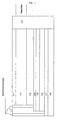
- the layer build-up of which has been given hereinbefore comprises, sequentially,
- Said transparent support is preferably composed of polyethylene terephthtalate, polyethylene napththalate, polymethyl methacrylate, polycarbonate, polyvinyl chloride; (colored) glass, etc., without being limitative thereto, and is very suitable to guide the stimulated emission light from the stimulable phosphors in the storage phosphor panel by light-piping to the "detection" unit through a filter layer at the border of the card along a large thin slit.
- Read-out, after having passed the (optical) "FILTER” layer (as e.g.
- a "BG3" glass filter surrounding the edges with an optical filter transmitting exclusively energy released by said storage phosphor panel can proceed by an array of optical fibres(see: “DETECTION”), collecting the light to a photo-multiplier and converting it therein in an electrical signal.
- said means for absorbing UV-irradiation comprises a storage phosphor panel capable to store radiation energy originating from radiation having a wavelength of up to 350 nm which is highly sensitive to the said radiation.
- storage phosphors or photostimulable phosphors of the storage phosphor panel present in the personal monitor of the present invention are sensitive to a radiation dose of from about 20 mR or more (in the case of "static read-out” or “discontinuous” read-out) of the light emitted by the storage phosphor after stimulation) and even from about 5 mR or more (in the case of scanning of the storage phosphor panel, also called “continuous” or “dynamic” read-out).
- Storage phosphor panels or photostimulable phosphor panels are well-known in the field of "digital radiography", also called “computed radiography", wherein a system has been developed wherein X-rays transmitted by an exposed object (such as the body of a patient) are stored in a photostimulable phosphor screen.
- Digital radiography also called “computed radiography”
- Systems for computed radiography using storage phosphor technology are commercially available e.g. under trade name ADC70, ADC Compact and ADC Solo from Agfa-Gevaert N.V., Mortsel, Belgium and under trade name FCR7000 and FCR AC1 from Fuji Film, Japan.
- Such a photostimulable phosphor screen or panel essentially comprises a layer of photo-stimulable luminescent material which comprises a suitable storage phosphor, a suitable binder material and a support whereto the said supported phosphor layer is adhered.
- said photo-stimulable material is a self-supporting material. Therefore a special type of phosphor is required, known as a "photostimulable phosphor", which, when being incorporated in a panel is exposed to incident pattern-wise modulated X-rays and as a result thereof temporarily stores therein energy contained in the X-ray radiation pattern.
- electroluminescent energy originating from an electroluminescent layer stimulates the energy-loaded storage phosphor particles in the storage phosphor panel in order to stimulate release of stored energy as light energy that is detected and converted to electrical signals which can be processed to produce an irradiation energy pattern or spectrum (after pixelwise energy release) or even a visible image (after imagewise exposure followed by pixelwise energy release) or to quantify integral amounts of stored energy.
- the phosphor should store as much as possible of the incident X-ray energy and emit as little as possible of the stored energy until stimulated by electroluminescent energy.
- the storage phosphor coated onto a panel used as a substrate (like the transparent medium e.g.) or a self-supporting storage phosphor panel is most suitable to include the photostimulable phosphor.
- the said photostimulable or storage phosphor can be made sensitive in order to capture UV/blue light radiation as has been set forth e.g. in Phys. Review Letter, Vol. 65(19), p. 2438-41(1990); in Prog. Nat. Sci., Vol.3(2), p. 160-164(1993) and in Phys.Status Solidi, Vol.136(1), p. 241-246(1993).
- Examples of stimulable phosphors employable in the radiation image storage panel used in the personal monitor of the present invention include:
- the above-described stimulable phosphors are given by no means to restrict the stimulable phosphor employable in the present invention. Any other phosphor can be also employed, provided that the phosphor gives stimulated emission when excited with stimulating rays having a wavelength ⁇ a after exposure to the radiation which should be detected. It is understood that this doesn't mean that the stimulating radiation should be perfectly monochromatic and restricted to rays having a wavelength ⁇ a , but that the spectrum can be broader, including rays having a wavelength ⁇ a , preferably representing therein the rays having the highest intensity.
- Barium fluorohalide phosphors more preferably barium fluorobromide phosphors, and still more preferably europium doped barium fluorobromide phosphors, cannot only be energized to an excited state by X-rays but also by UV-rays, and can then be stimulated by light within a first wavelength range in order to return to the ground state with the emission of light within a second wavelength range.
- the stimulating radiation is arranged in order to have a different wavelength from the emitted light .
- a europium activated or doped bariumfluorobromide storage phosphor wherefore the stimulating light is situated within the range of 600-700 nm (red light, clearly differing from radiation having a wavelength ⁇ a corresponding with energy for which the stimulable phosphor is sensitive to stimulation) and the emitted light is situated within the range of 350-450 nm (blue light).
- said storage phosphor absorbing radiation having a wavelength up to 350 nm is coated on a support in form of a powder of phosphor dispersed in a binder.
- the powder comprises phosphor particles having a particle size distribution with an average volume diameter (d v50 ) between 1 ⁇ m and 100 ⁇ m.
- the amount of storage phosphor present on the support of the indicator in the case of a phosphor powder, ranges from 10 mg/cm 2 to 400 mg/cm 2 , and more preferably the amount of phosphor powder ranges from 20 mg/cm 2 to 200 mg/cm 2 .
- the storage phosphor can in principle be present as a single crystal on the support of the panel of the device according to the present invention.
- an electroluminescent screen or panel is provided in the layer-build-up of the device according to the present invention.
- Such a screen is compact as it is available as a thin foil.
- the electroluminescent phosphors used are chosen with respect to the stimulation properties of the storage phosphor to be stimulated.
- E.g the electroluminescent element used in order to stimulate a storage phosphor with a maximum stimulability in the red region of the visible spectrum will incorporate an electroluminescent phosphor with a light emission tuned to match said wavelength region.
- Red emitting electroluminescent phosphors are e.g. ZnS:Mn, a Mn activated fluorphlogopite phosphor with formula KMg 3 (Si 3 Al)O 10 F 2 :Mn as disclosed in US-A 5,582,768 and SrS:Eu.
- a blue-green emitting luminescent phosphor is e.g., SrS:Ce
- green emitting luminescent phosphors are, e.g.
- Blue emitting luminescent phosphors are e.g., Sr x Ca 1-x Ga 2 S 4 :Ce with 0 ⁇ x ⁇ 1, phosphors as described in US-A 5,598,059, with formula M 2+ M 3+ 2 X 4 :RE, wherein M 2+ is a metal selected from the group consiting of Mg, Ca,Sr and Ba, M 3+ is a metal selected from the group consiting of Al, Ga and In, X is an element selected from the group consisitng of Se and S and RE is an activator selected from the group consisiting of Ce and Eu, a Ti-activated ⁇ -Zirconiumphosphate phosphor with formula Zr 1-x Ti x (HPO 4 ) 2 .H 2 O as disclosed in US-A 5,582,768.
- electroluminescent phosphors have been disclosed in US-A 5,616,285 wherein electroluminescent phosphors based on lamellar intercalation compounds doped with various dopants in order to select the emission color of the doped compound are disclosed.
- said device further comprises an isolating layer which is a layer containing pigments selected from the group consisting of barium titanate, magnesium oxide and barium silicate.
- Said layer is in all embodiments situated adjacent to the electroluminescent layer and between said layer and the energy source providing energy in order to provoke luminescence of the luminescent phosphors in the said luminescent layer, whereby the luminescent energy is captured by the storage phosphors in the photostimulable phosphor layer.
- the transparent electrode layer optionally present as in Fig. 1 should be transparent as electroluminescent light should pass through the layer and reach the photostimulable phosphor particles in order to store energy in an efficient way, even after provoking luminescence of the electroluminescent phosphors by application of a lower voltage over the electrodes if compared with the layer build-up as represented in the other Figures 2-6 e.g. where a higher voltage is required due to the larger distance between the electrode layers.
- Said transparent electrode layer acting as an electrode is a transparent layer of indium-tinoxide (ITO) or of a transparent support carrying a transparent conductive polymer layer composed e.g. of poly-ethylene-dioxythiophene (also called PEDT), polypyrole, polyaniline and the like.
- ITO indium-tinoxide
- PEDT poly-ethylene-dioxythiophene
- the device is preferably present in form of a handsome card , just as a credit card, the device has two (parallel) largest sides and surrounding edges which should be covered with outermost layers.
- the device thus contains as outermost layers covering said device
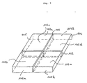
- said device has an electroluminescent layer as set forth hereinbefore which is emitting said stimulation light pixelwise in order to read-out said storage phosphor panel "imagewise" with respect to optionally differing energies detected at differing sites on the device (made different e.g. as a consequence of differing filters divided in a predetermined pattern over the surface of the device in order to detect irradiation having differing energies).
- said electroluminescent element is as large as or larger than the storage phosphor panel to be scanned, then no physical movement is necessary.
- the stimulating light pixel-wise driven by a matrix electrode structure thus travels over the storage phosphor plate by sequentially switching the pixels of the electroluminescent element on and off followed inbetween by detection of the subsequent signals representative for the energy pattern absorbed by the storage phosphors during irradiation with differing energies.
- Each of the row and column electrodes required to get pixelwise activation by an electrical field of the electroluminescent phosphors and further pixelwise stimulation of the stimulable phosphors in the storage phosphor panel is therefore coupled to a voltage source adapted for applying an electric potential to each of said electrodes separately.
- the respective voltages are chosen such that an electric field with a field strength beyond the threshold for making the electroluminescent phosphor emit light is only reached where both electrodes cross.
- a first voltage is applied to the first row electrode and a second voltage is consecutively applied to each of the column electrodes, thus light is emitted consecutively by all matrix points on the first row, then said first voltage is applied to the second row electrode and said second voltage is again consecutively applied to each of the column electrodes, thus light is emitted consecutively by all matrix points on the second row.
- a dot of emitted light equal in size to the pixel created by the row and column electrodes travels over the entire surface of the electroluminescent panel and can pixel-wise stimulate the storage phosphor.
- the voltage source for driving the electrodes can be a DC-voltage source as well as an AC-voltage source, the latter being preferred.
- the electroluminescent element for use in the device of the present invention can be pixel-wise driven by a passive matrix electrode structure as well as by an active matrix electrode structure.
- An electroluminescent element pixel-wise driven by an active matrix electrode structure is preferred for use in the present invention. Since the EL-element is only intended to stimulate a storage phosphor, it is only needed to drive the element on an on or out basis (binary driven). Thus the driver can be made quite simple, even for a pixel-wise driven electroluminescent device.
- the electroluminescent element for use in the device of the present invention may further comprise any additional layer necessary for the functioning of it: it can, e.g., comprise isolating layers for isolating the electroluminescent compound from the electrodes, protective layers on top of the electrodes, barrier layers for protecting the element from moisture, etc..
- Active matrix electroluminescent elements for use in the device of the present invention have e.g. been disclosed in US-A's 5,767,623; 5,650,692; US-A 5,712,528; etc.. These are AC-driven thin film electroluminescent elements (AC TFEL). Also electroluminescent thick film materials as described in, e.g., WO 93/23972 are very useful in the device of the present invention.
- the electroluminescent elements for use in the device of the present invention need only to emit monochrome light.
- the row electrodes or the column electrode or both are transparent electrodes, e.g. made of a transparent support with a layer of indium-tin-oxide (ITO) or of a transparent support carrying a transparent conductive polymer layer as already mentioned hereinbefore.
- ITO indium-tin-oxide
- the electroluminescent compounds used, inorganic as well as organic, are chosen with respect to the stimulation properties of the storage phosphor to be stimulated. So e.g. the electroluminescent compound used to stimulate a storage phosphor with a maximum stimulability in the red region of the visible spectrum, will incorporate an electroluminescent compound with a light emission tuned to match said wavelength region.
- an electroluminescent element comprising an inorganic electroluminescent compound (an electroluminescent phosphor) to stimulate a storage phosphor in a method according to this invention, is preferred, since such devices require generally lower voltage for its activation.
- a device which is sensitive to incident radiation energy which has a wavelength of 350 nm or less. Said incident radiation energy is thus measured integrally or as a spectrum of differing energies, depending on the integral or pixel-wise read-out of the device as described hereinbefore.
- said filter covering the largest surface sides from the device according to the present invention absorbs radiation having a wavelength of 350 nm or more.
- the storage phosphor panel (supported or self-supporting) making part of the device according to the present invention, after being exposed to irradiation thus stores part of the energy of the X-rays and is in such a position with respect to the EL-layer that the light emitted by the EL-layer can reach the storage phosphor and stimulate the phosphor in order to release the stored energy. By doing so, at least part of the stored energy is released as stimulation light. As the amount of stimulated light is proportional to the amount of energy stored in the storage phosphor, the stimulated light can then be captured and converted to an electric signal for further processing.
- the device according to the present invention has a filter layer which is divided over its surface in differing parts absorbing radiation of differing energies in order to selectively detect differing incident radiation energy, originating e.g. from differing radiation sources having a wavelength of 350 nm or less.
- the device according to the present invention is then e.g. covered with a lead filter having differing thicknesses or, depending on the energies to be detected, differing metal filters, for the said differing parts of the surface.
- a lead filter having differing thicknesses or, depending on the energies to be detected, differing metal filters, for the said differing parts of the surface.
- the electroluminescent device normally consisting of one unit, has been divided into 4 separate units (see parts 103 a,b,c and d), which can have been constructed as a whole or apart and be brought together, wherein part (103a) is e.g. sensitive for energies of a Co 60 -source and even higher; wherein part (103b) is e.g. sensitive for energies of an Ir 192 -source, part (103c) for energies between 50 and 150 nm and part (103d) for ultraviolet rays. It is clear that such division of the device as presented hereinbefore is not limitative and that alternatives with respect to shape and energy to be detected are also possible.
- Capturing of the stimulated light can be performed by a light guiding member to a photomultiplier in the same way as it is done in methods wherein the storage phosphor panel is pixel-wise stimulated by a laser beam as in digital radiography.
- the capturing means for the stimulated light as described above (a line- or matrix type array of CCD's or a line or matrix type of a gaseous photondetector) can be used when the storage panel is stimulated by a pixel-wise driven EL-element.
- charge couple devices CCD's
- a matrix of gaseous photon detectors or a line or matrix shaped detector containing ⁇ -Si coupled to TFT's Thin Film Transistors
- an X-ray image detector comprising a two-dimensional position-sensitive, gaseous photon detector
- an X-ray sensitive storage means for storing an X-ray image
- storage means is capable of emitting image-wise modulated light
- two-dimensional position-sensitive gaseous photon detector arranged to detect said imagewise modulated light
- said two-dimensional position sensitive gaseous photon detector comprising a photocathode arranged for receiving image-wise modulated light emitted by said storage means and being operative to provide in response to said image-wise modulated light an output of electrons
- a gaseous electron multiplier being operative on the output of electrons from said photocathode to provide an electron avalanche comprising an increased number of electrons
- an electrode assembly comprising at least one anode and at least one cathode, said electrode assembly being
- the stimulated light can be coupled to the capturing means by means of a self-focusing lens or by means of an array of tapered or non-tapered optical fibres.
- a line shaped capturing means this is preferably as long as the longest dimension of the line-shaped EL-element, which in turn is preferably as long as one of the two dimensions of the storage panel to be stimulated.
- the stimulated light can be guided to the pixel-wise capturing means by tapered optical fibres.
- the pixel-wise two dimensional light capturing means having an area large enough to cover at least the total area of the phosphor panel that is stimulated can be a single light capturing means, or can be made up by juxtaposition of several smaller light capturing means.
- Such means made up by juxtaposition of several smaller capturing means for the stimulated light from a storage phosphor panel with CCD's are disclosed in European application 98200152.1 filed on January 20, 1998, titled "Method for obtaining an electrical representation of a radiation image using CCD sensors".
- the EL-layer, the storage phosphor layer and the matrix shaped capturing means preferably have the same area.
- the matrix shaped light detector for pixel-wise capturing the stimulated light can be a two-dimensional matrix of charge couple devices (CCD's) as well as a two dimensional matrix of a gaseous photon detectors.
- the electroluminescent layer, the storage phosphor layer and the matrix shaped capturing means have the same area.
- the phosphor part and the electroluminescent part can be glued together by an adhesive between the support of the storage phosphor part and the protective layer. It is also possible to apply the storage phosphor directly on the protective layer and to omit the support. Structuring the device in this way can increase the achievable image quality.
- Any other way of combining the electroluminescent part and the phosphor part of the device can be used as well, e.g. both parts can be kept together by electrostatic attraction, by clamping the sides of the device together, etc.. Moreover coating electroluminescent particles and stimulable phosphor particles in one and the same layer is also possible as has been illustrated in the Figures.
- Provoking stimulation by electroluminescent energy generated from said electroluminescent layer thus proceeds, in a preferred embodiment, by electrical excitation along two electrode layers at both sides of the storage panel(s) in order to be coupled to a voltage source adapted for applying an electrical potential between said two electrode layers.
- Said two electrode layers therefore preferably represent a matrix of row and column electrodes, present at one and the other side of the electroluminescent layer respectively and mounted perpendicularly to each other, in order to be coupled to a voltage source adapted for applying an electrical potential to each of said electrodes separately.
- the stimulated light generated into the device according to the present invention is detected as a signal by capturing means and brought to a photomultiplier where the said signal is further processed.
- the stimulation light thus leaves the storage panel and is captured by capturing means and is brought to a photomultiplier where the signal is further processed.
- the device according to the present invention preferably has as capturing means a line of optical fibers.
- the detectable signal(s) is(are) processed and stored in an electronic memory or chip, wherein said electronic memory is a DSP(digital signal processing)-chip.
- the device itself thus preferably comprises an electronic memory being a DSP(digital signal processing)-chip in order to quantitatively determine the irradiation energy captured between the time of entering e.g.
- Said DSP-chip moreover offers digital data of quantitatively detected integral overexposure or underexposure dose of radiation having a wavelength of 350 nm or less, by calculation e.g. of the difference between detected radiation values and maximum tolerable values per irradiation period (expressed as body equivalent).
- Means can further be provided to connect the DSP-chip with a network in order to transfer digitally stored data with respect to irradiation of the device according to the present invention (being proportional with irradiation of a person and/or an object in proximate contact therewith) to a central computer.
- the divice according to the present invention is thus a personal monitor for use as an indicator of the said incident radiation and comprises means for absorbing said incident radiation, wherein the said radiation is proportionally sensitive to the said radiation when simultaneously with the said indicator an object (as the human body) is exposed thereto.
- radiation energy having a wavelength of 350 nm or less and, in particular, incident radiation substantially composed of UV-B and UV-A rays in the wavelength range of from 250 to 350 nm is simultaneously captured by means comprising a storage phosphor panel and by the human skin, exposed to said incident radiation, originating from sunlight or from solar panels present in "solar centres".
- incident radiation substantially composed of UV-B and UV-A rays in the wavelength range of from 250 to 350 nm
- the personal monitor or indicator as device according to the present invention thus accompanying the person who wants to know what dose of harmful irradiation he/she has captured during the time he/she has been exposed to the said radiation doesn't need to be provided with a shutter element in order to start exposure by said irradiation.
- the processed data can be compared with data about maximum tolerable exposure times for differing energy levels stored e.g. digitally in look-up tables which may be present in a read-out apparatus or on the net-work with which a connection is provided.
- results obtained are then stored in digital form in a digital memory storing medium in the personal monitor or via a network with hospitals.
- a report on the display of the read-out apparatus may appear and the report can be made available to the interested person as a hard-copy, in form of e.g. a printed ticket. On that ticket the time of exposure and the recommended maximum tolerable time for differing exposure energies that have been captured may appear.
- a personalized preview for the maximum tolerable irradiation which is acceptable for that day and for the following day or days (e.g. over a period of the coming 3 days) is preferably reported.
- This value can also further be stored on the said digital memory storing medium making part of the personal monitor device according to the present invention.
- the person being exposed to irradiation having differing energies is thus able to controll if the daily irradiation exposure is still within the tolerable boundaries in order to detect possible health risk in the future.
- the storage phosphor panel of the personal monitor device comprises storage phosphors having a dark decay of more than 2 hours in order to be able to read out the stored energy with high enough a precision in the dedicated read-out apparatus which will be described hereinafter in different embodiments.
- dark decay In practice it is necessary to read out and to get an acceptable result, even 15 hours after ending irradiation exposure.
- the phenomenon called “dark decay” should be understood as follows.
- a storage phosphor having stored energy after being exposed to incident radiation as in this application, can release said stored energy also without irradiation by stimulation light. This way of releasing energy is called “dark decay”.
- the dark decay is determined by a procedure wherein irradiation of the phosphor proceeds by radiation of 70 kVp, immediately followed by stimulating said phosphor by a He-Ne laser of 30 mW.
- the fluorescent light emitted by the phosphor upon stimulation is then collected and brought e.g. to a photomultiplier (as e.g.
- the commercially available HAMAMATSU R 376) giving a corresponding electrical current, proportional to the amount of initially emitted fluorescent light.
- the irradiation of the phosphor with the said radiation can be repeated, but the reading of the amount of stimulable light for a given intensity of stimulating energy can only take place after keeping the irradiated storage phosphor with its stored energy for a given time in the dark. This process is repeated and the time after which the emitted fluorescent light (and thus the energy remaining in the phosphor) of a phosphor kept in the dark, has fallen to a level equal to 1/e ("e" being the basic number for natural logarithm scale) is recorded as "dark decay".
- the storage phosphor preferably has a dark decay longer than 120 minutes (2 hours) and preferably even much larger.
- Another factor determining the accuracy is the weakening of the signal or the decay time: although the calculation still leads to perfect results, even with a weakening factor of 2, such high precision can only be attained if such a "half-life" is not exceeding a recommended time interval of about 15 hours. The said time interval however is really sufficient to detect the dose captured in one day.
- Application of the "power law" method described above permits a reproducible detection of a minimum dose of 10 ⁇ R (88 nGray) with a standard deviation of at most 5 %.
- Fitting proceeds by means of a least square analysis.
- Parameters A, t 0 and n are determined in such a way that the sum of the squares of the deviations between the measured curve and the theoretical curve is minimized. Taking into account the values so obtained, permits to generate a theoretical curve, showing no noise anymore. Integration under the said generated theoretical curve from the start of the curve up to the "1/e"-line makes improve the reproducibility as set forth hereinbefore (up to a standard deviation of 3 %, even at a low dose) and allows to detect a minimum dose of 2 ⁇ R, being equivalent with a dose of 20 nGray.
- Preferred read-out providing means are further described hereinafter.
- the irradiation of the phosphor with penetrating radiation is repeated, but the reading of the amount of stimulable light for a given intensity of stimulating energy only takes place after keeping the irradiated phosphor for a given time in the dark. This process is repeated and the time after which the emitted fluorescent light, (and thus the energy remaining in the phosphor) of a phosphor kept in the dark, has fallen to 1/e is recorded as "dark decay".
- a storage phosphor for use in the first embodiment of this invention, has preferably a dark decay longer than 120 minutes (2 hours).
- an indicator according to the present invention has a storage phosphor panel comprising storage phosphors with an electronically erasable memory, wherein erasure is performed in the case of reusable personal monitors or devices as in the present invention at the end of the readout procedure in the apparatus wherein the loaded stimulable phosphor is read out.
- the light tight covering of the phosphor further offers the advantage that a storage phosphor with high "erasability” but with slow “dark decay” can advantageously be used in the context of the present invention.
- the photostimulable phosphor layer is subjected to an erasure operation in order to remove any residual image left in the layer with the purpose to re-use the indicator.
- the stored radiation energy is not completely eliminated by the read out process.
- it is fed from the readout station in the apparatus to an erasing station, where part of the energy still remaining in the phosphor after read out is erased by subjecting the screen to a uniform illumination by means of erasing light. But even if a photostimulable phosphor screen is erased after being read out, it is still possible that residual energy is left on the read out screen or panel. This may be caused by non-optimal adjustment or control of the amount of erasing energy that is applied to the photostimulable phosphor screen.
- Non-optimal adjustment of the applied amount of erasing energy may be the result of the fact that the period of time during which a photostimulable phosphor screen is subjected to erasing light is too short (for example as a result of incorrect transport speed of the screen), or that the amount of energy emitted by the erasing light sources to the phosphor screen to be erased does not correspond with the set amount (for example due to a failing lamp), etc.. Only few of the possible causes have been mentioned, other causes may be envisaged. When a storage panel that has not been erased to an acceptable level is re-used and again exposed to radiation, the residual signal left in the screen will be detected accumulatively.
- Erasure of photostimulable phosphor screens is well-known in the art and can e.g. be obtained by subjecting the layer to an overall illumination with light within the stimulation wavelength range, wherein this stimulation wavelength can again be generated via electroluminescent layers or panels.
- this stimulation wavelength can again be generated via electroluminescent layers or panels.
- the high voltage supply is turned off in the case wherein a photomultiplier is used in order to prevent damaging of the read out electronics.
- the read out electronics are also subjected to a reset operation before being used to read a subsequent radiation dose.
- the apparatus therefore comprises a circulatory feed system for feeding photostimulable phosphor sheets (comprised in a device) along a predetermined circulatory feed path comprising in sequence an exposure unit, a read out unit and an erasure unit. Prior to successive recording of images on the sheets, any remaining images are erased therein. After erasure the sheet is again read out and the signal level is threshold.
- the remaining image is erased again in the image erase unit.
- the erasure step is repeated until the remaining image is sufficiently small.
- the apparatus thus provides a method of reading an amount of radiation energy stored in a photostimulable phosphor panel of the device according to the present invention, comprising as steps:
- the energy remaining in the panel after erasure should be sufficiently small.
- the signal level detected when the panel is read a second time at highest machine sensitivity is a 1000 times smaller than the maximum dynamic range of the read out apparatus at said highest sensitivity.
- step (5) In case the signal resulting from step (5) exceeds a preset threshold signal value, this indicates that the stimulable phosphor layer has not been erased to an adequate extent allowing re-use of the device. In this case the panel should be erased once more or it is to be decided that the particular device cannot be re-used further. In that case the apparatus can swallow the device in order to recycle the different components thereof, as e.g. particularly the housing and the phosphor thereof.
- An apparatus for reading a radiation signal (irradiation energy) that has been stored in a photostimulable phosphor panel may comprise
- the apparatus of the above-described kind may have a single read-out unit.
- Such an apparatus is particularly advantageous from the viewpoint of economy and compact design.
- a read out unit may preferably be located inbetween the input of the apparatus and the erasing unit.
- the apparatus may further comprise means for transporting the device from the input unit via the read out unit to the erasure unit and means for reversing the transport direction so that the panel is transported from the erasure unit through the read out unit to the input unit.
- the means for transporting the panel may perform the transport substantially in a single plane.
- the phosphor may be stimulated for a longer time with the same electroluminescent irradiation in order to erase the phosphor. It can also be transported to a special erasing unit but it is clear that this embodiment is in favor of saving time and space. After erasing the phosphor may be measured again. This residual signal can be compared with the first signal and the difference between these signals may be considered as representative for the dose.
Landscapes
- Physics & Mathematics (AREA)
- Health & Medical Sciences (AREA)
- Life Sciences & Earth Sciences (AREA)
- General Physics & Mathematics (AREA)
- High Energy & Nuclear Physics (AREA)
- Molecular Biology (AREA)
- Spectroscopy & Molecular Physics (AREA)
- Conversion Of X-Rays Into Visible Images (AREA)
Claims (16)
- Dispositif pour enregistrer et pour emmagasiner de l'énergie d'un rayonnement incident et pour lire ladite énergie, comprenant :un luminophore stimulable (1.3) qui absorbe et qui emmagasine ladite énergie et qui peut être stimulé avec une longueur d'onde λa, le dispositif étant caractérisé en ce qu'il comprend en outre :un luminophore électroluminescent (1.5) qui émet, lors de l'application d'un champ électrique, une lumière stimulante avec ladite longueur d'onde λa, ledit dispositif étant équipé d'un moyen pour appliquer un champ électrique sur ledit luminophore électroluminescent (1.5), ledit luminophore stimulable (1.3) et ledit luminophore électroluminescent (1.5) étant disposés, l'un par rapport à l'autre, de telle sorte que ladite lumière émise par ledit luminophore électroluminescent (1.5) atteint ledit luminophore stimulable (1.3) afin de stimuler ledit luminophore dans le but de libérer la lumière stimulée sous la forme d'un signal détectable.
- Dispositif selon la revendication 1, comprenant successivementun panneau contenant un luminophore d'emmagasinage (1.3) à titre de milieu d'emmagasinage pour absorber de l'énergie d'un rayonnement incident ;en position adjacente audit panneau, d'un côté, un support transparent (1.2) qui permet d'exposer ledit panneau contenant un luminophore d'emmagasinage (1.3) à ladite énergie de rayonnement incident ;en position adjacente audit support, de l'autre côté et/ou à l'état incorporé dans le panneau contenant un luminophore d'emmagasinage, en formant ainsi une couche dans ce cas (3.4), une couche électroluminescente (1.5) émettant une lumière stimulante avec ladite longueur d'onde λa pour pouvoir lire ledit panneau contenant un luminophore d'emmagasinage (1.3) ;en position adjacente à ladite couche électroluminescente (1.5) et à une plus grande distance par rapport au panneau contenant un luminophore d'emmagasinage (1.3), successivement :une couche isolante (1.6) et une couche conductrice (1.7).
- Dispositif selon la revendication 2, comprenant, dans l'ordre, ledit panneau contenant un luminophore d'emmagasinage (1.3), ladite couche électroluminescente (1.5) formant le cas échéant une seule couche (3.4) de manière conjointe avec ledit panneau contenant un luminophore d'emmagasinage (1.3), ladite couche isolante (1.6) et ladite couche conductrice (1.7) étant successivement présentes de part et d'autre dudit support transparent (1.2).
- Dispositif selon la revendication 2 ou 3, contenant en outre, à titre de couches situées le plus à l'extérieur, recouvrant ledit dispositif :sur un de ses grands côtés ou sur les deux, à savoir le côté supérieur et/ou le côté opposé, ladite couche étant une couche filtrante (1.1) absorbant l'énergie qui ne doit pas étrs détectée au cours de l'exposition ;aux bords périphériques ou aux limites entourant les couches, une couche périphérique qui recouvre au moins en partie lesdites limites, ladite couche étant une couche faisant office de filtre optique qui transmet à titre exclusif l'énergie libérée par ledit panneau contenant un luminophore d'emmagasinage (1.3).
- Dispositif selon les revendications 2 à 4, dans lequel ladite couche électroluminescente (1.5) émet ladite lumière stimulante en forme de pixels pour pouvoir lire en forme d'image ledit panneau contenant le luminophore d'emmagasinage, en équipant par conséquent ledit dispositif d'un moyen pour pouvoir appliquer un champ électrique sur ledit luminophore électroluminescent via des électrodes constituées par des rangs et des colonnes (1.4) prévues de part et d'autre de ladite couche électroluminescente (1.5) et montées en position réciproquement perpendiculaire, ledit moyen étant couplé à une source de tension conçue pour appliquer un potentiel électrique sur chacune desdites électrodes (1.4), de manière séparée.
- Dispositif selon l'une quelconque des revendications 1 à 5, dans lequel ladite énergie de rayonnement incident possède une longueur d'onde λa de 350 nm ou moins.
- Dispositif selon l'une quelconque des revendications 4 à 5, dans lequel, au cours de l'exposition, ledit filtre (1.1) absorbe un rayonnement possédant une longueur d'onde de 350 nm ou plus.
- Dispositif selon l'une quelconque des revendications 4 à 7, dans lequel ledit filtre (1.1) est subdivisé, sur sa surface, en différentes parties absorbant un rayonnement de différentes longueurs d'ondes, dans le but d'obtenir une détection sélective de l'énergie d'un rayonnement incident différent.
- Dispositif selon la revendication 8, dans lequel ledit filtre (1.1) est un filtre en plomb possédant des épaisseurs différentes pour lesdites différentes parties de la surface.
- Dispositif selon l'une quelconque des revendications 1 à 9, dans lequel le dispositif est conçu de telle sorte que la lumière stimulée peut être détectée sous la forme d'un signal via un moyen de saisie et est acheminée à un photomultiplicateur dans lequel ledit signal est soumis à un traitement ultérieur.
- Dispositif selon la revendication 10, dans lequel ledit moyen de saisie représente une ligne de fibres optiques.
- Dispositif selon l'une quelconque des revendications 1 à 11, comprenant en outre une mémoire électronique.
- Dispositif selon la revendication 12, dans lequel ladite mémoire électronique est une puce de traitement de signaux numériques.
- Dispositif selon l'une quelconque des revendications 2 à 13, dans lequel ladite couche isolante est une couche contenant des pigments choisis parmi le groupe constitué par le titanate de baryum, l'oxyde de magnésium et le silicate de baryum.
- Procédé pour déterminer, d'une manière quantitative, des valeurs emmagasinées de ladite énergie de rayonnement incident, comprenant les étapes consistant à :i) procurer un dispositif selon l'une quelconque des revendications 1 à 14 ;ii) exposer ledit dispositif à un rayonnement incident ;iii) lire ledit panneau contenant un luminophore d'emmagasinage en provoquant une stimulation de libération d'énergie desdits luminophores d'emmagasinage via une couche électroluminescente émettant une lumière stimulée :iv) détecter, par voie numérique, l'énergie libérée à partir dudit panneau contenant un luminophore d'emmagasinage, via un détecteur ;v) effacer l'énergie résiduelle emmagasinée.
- Procédé pour absorber ou capter de l'énergie et pour reproduire de manière quantitative ladite énergie émanant d'un rayonnement pénétrant possédant des énergies différentes via le dispositif selon l'une quelconque des revendications 1 à 14, comprenant les étapes consistant à :i) exposer le luminophore d'emmagasinage à un rayonnement pénétrant,ii) emmagasiner l'énergie émanant dudit rayonnement pénétrant dans ledit luminophore d'emmagasinage ;iii) libérer au moins une partie de ladite énergie emmagasinée sous la forme d'une lumière stimulée Possédant une longueur d'onde, en stimulant ledit luminophore avec un rayonnement électromagnétique dont la longueur d'onde est supérieure à 400 nm ;etiv) lire ladite lumière stimulée, le procédé étant caractérisé en ce que ledit luminophore est stimulé par un rayonnement électromagnétique émanant d'un dispositif électroluminescent entraíné en forme de pixels.
Priority Applications (1)
| Application Number | Priority Date | Filing Date | Title |
|---|---|---|---|
| EP19990203167 EP1001277B1 (fr) | 1998-11-10 | 1999-09-28 | Appareil personnel et réutilisable de surveillance de radiation et procédé de détermination de la quantité de radiation à partir de mesures faires avec l'appareil |
Applications Claiming Priority (3)
| Application Number | Priority Date | Filing Date | Title |
|---|---|---|---|
| EP98203794 | 1998-11-10 | ||
| EP98203794 | 1998-11-10 | ||
| EP19990203167 EP1001277B1 (fr) | 1998-11-10 | 1999-09-28 | Appareil personnel et réutilisable de surveillance de radiation et procédé de détermination de la quantité de radiation à partir de mesures faires avec l'appareil |
Publications (2)
| Publication Number | Publication Date |
|---|---|
| EP1001277A1 EP1001277A1 (fr) | 2000-05-17 |
| EP1001277B1 true EP1001277B1 (fr) | 2005-12-07 |
Family
ID=26150856
Family Applications (1)
| Application Number | Title | Priority Date | Filing Date |
|---|---|---|---|
| EP19990203167 Expired - Lifetime EP1001277B1 (fr) | 1998-11-10 | 1999-09-28 | Appareil personnel et réutilisable de surveillance de radiation et procédé de détermination de la quantité de radiation à partir de mesures faires avec l'appareil |
Country Status (1)
| Country | Link |
|---|---|
| EP (1) | EP1001277B1 (fr) |
Families Citing this family (1)
| Publication number | Priority date | Publication date | Assignee | Title |
|---|---|---|---|---|
| CN118380167B (zh) * | 2024-06-24 | 2024-08-16 | 中国工程物理研究院激光聚变研究中心 | 一种x射线图像信息的抗干扰快速在线读取装置及方法 |
Family Cites Families (3)
| Publication number | Priority date | Publication date | Assignee | Title |
|---|---|---|---|---|
| FI84960C (fi) * | 1990-07-18 | 1992-02-10 | Planar Int Oy | Lysaemnesskikt foer elektroluminescensdisplay. |
| JPH07122366A (ja) * | 1993-10-27 | 1995-05-12 | Oki Electric Ind Co Ltd | 青色発光el素子 |
| JPH07335382A (ja) * | 1994-06-14 | 1995-12-22 | Sharp Corp | 薄膜el素子 |
-
1999
- 1999-09-28 EP EP19990203167 patent/EP1001277B1/fr not_active Expired - Lifetime
Also Published As
| Publication number | Publication date |
|---|---|
| EP1001277A1 (fr) | 2000-05-17 |
Similar Documents
| Publication | Publication Date | Title |
|---|---|---|
| US6642650B1 (en) | Refusable personal monitoring device | |
| US4803359A (en) | Method for detecting radiation image | |
| US6271528B1 (en) | Reusable personal sun-monitor | |
| EP1550885B1 (fr) | Feuille fluorescente pour detecteur de rayonnement, detecteur de rayonnement equipe d'une telle feuille et equipement de detection de rayonnement | |
| EP1351094B1 (fr) | Dispositif pour la reproduction d'image de rayonnement et méthode de reproduction d'image de rayonnement | |
| JPS6226440B2 (fr) | ||
| EP0079751A1 (fr) | Procédé pour éteindre le bruit des feuilles phosphore à stimuler | |
| US20010030302A1 (en) | System for digital radiography and dosimetry | |
| JP4204344B2 (ja) | 放射線画像形成材料および放射線画像形成方法 | |
| US4818877A (en) | Memory display system | |
| EP1001277B1 (fr) | Appareil personnel et réutilisable de surveillance de radiation et procédé de détermination de la quantité de radiation à partir de mesures faires avec l'appareil | |
| Dotzler et al. | Photoluminescence, optically stimulated luminescence, and thermoluminescence study of RbMgF3: Eu2+ | |
| Nanto et al. | Optically‐Stimulated Luminescent Dosimeters | |
| DE69928750T2 (de) | Wiederverwendbares personenbezogenes Strahlenmessgerät und Verfahren zur Bestimmung der Strahlenmenge unter Verwendung dieses Gerätes | |
| US6392249B1 (en) | Method for recording and reproducing images made by penetrating radiation using electroluminescent elements | |
| US5990485A (en) | Label for certifying an inspection by penetrating radiation | |
| US6114707A (en) | Label for certifying an inspection by penetrating radiation | |
| EP1001276B1 (fr) | Méthode d'enregistrement et de reproduction d'image obtenue par rayonnement utilisant elements électroluminescents | |
| US9081101B2 (en) | Sensitive charge for passive dosimetry, dosimeter comprising such a sensitive charge and system for reading by illumination for such a sensitive charge | |
| JP3015685B2 (ja) | 輝尽発光物質を利用した放射線種弁別方法 | |
| JP3105995B2 (ja) | ラドン検出方法、ラドンエネルギー蓄積装置、およびラドン検出装置 | |
| US20040227090A1 (en) | Dosimetry system | |
| EP0844497A2 (fr) | Etiquette pour la certification d'inspection par rayonnement pénétrant | |
| EP2068327A1 (fr) | Moyen de capture de rayonnement et procédé pour la détermination des doses de rayonnement cumulées. | |
| JP2003050278A (ja) | 放射線測定装置および方法 |
Legal Events
| Date | Code | Title | Description |
|---|---|---|---|
| PUAI | Public reference made under article 153(3) epc to a published international application that has entered the european phase |
Free format text: ORIGINAL CODE: 0009012 |
|
| AK | Designated contracting states |
Kind code of ref document: A1 Designated state(s): BE DE FR GB |
|
| AX | Request for extension of the european patent |
Free format text: AL;LT;LV;MK;RO;SI |
|
| 17P | Request for examination filed |
Effective date: 20001117 |
|
| AKX | Designation fees paid |
Free format text: BE DE FR GB |
|
| RAP1 | Party data changed (applicant data changed or rights of an application transferred) |
Owner name: AGFA-GEVAERT |
|
| 17Q | First examination report despatched |
Effective date: 20040722 |
|
| GRAP | Despatch of communication of intention to grant a patent |
Free format text: ORIGINAL CODE: EPIDOSNIGR1 |
|
| RTI1 | Title (correction) |
Free format text: REUSABLE PERSONAL RADIATION MONITORING DEVICE AND METHOD FOR DETERMINING RADIATION QUANTITY MONITORED WITH THE DEVICE |
|
| GRAS | Grant fee paid |
Free format text: ORIGINAL CODE: EPIDOSNIGR3 |
|
| GRAA | (expected) grant |
Free format text: ORIGINAL CODE: 0009210 |
|
| AK | Designated contracting states |
Kind code of ref document: B1 Designated state(s): BE DE FR GB |
|
| PG25 | Lapsed in a contracting state [announced via postgrant information from national office to epo] |
Ref country code: BE Free format text: LAPSE BECAUSE OF FAILURE TO SUBMIT A TRANSLATION OF THE DESCRIPTION OR TO PAY THE FEE WITHIN THE PRESCRIBED TIME-LIMIT Effective date: 20051207 |
|
| REG | Reference to a national code |
Ref country code: GB Ref legal event code: FG4D |
|
| REF | Corresponds to: |
Ref document number: 69928750 Country of ref document: DE Date of ref document: 20060112 Kind code of ref document: P |
|
| ET | Fr: translation filed | ||
| PLBE | No opposition filed within time limit |
Free format text: ORIGINAL CODE: 0009261 |
|
| STAA | Information on the status of an ep patent application or granted ep patent |
Free format text: STATUS: NO OPPOSITION FILED WITHIN TIME LIMIT |
|
| 26N | No opposition filed |
Effective date: 20060908 |
|
| REG | Reference to a national code |
Ref country code: GB Ref legal event code: 746 Effective date: 20070213 |
|
| REG | Reference to a national code |
Ref country code: GB Ref legal event code: 732E |
|
| REG | Reference to a national code |
Ref country code: FR Ref legal event code: TP |
|
| PGFP | Annual fee paid to national office [announced via postgrant information from national office to epo] |
Ref country code: GB Payment date: 20080925 Year of fee payment: 10 |
|
| PGFP | Annual fee paid to national office [announced via postgrant information from national office to epo] |
Ref country code: DE Payment date: 20080925 Year of fee payment: 10 |
|
| PGFP | Annual fee paid to national office [announced via postgrant information from national office to epo] |
Ref country code: FR Payment date: 20080924 Year of fee payment: 10 |
|
| GBPC | Gb: european patent ceased through non-payment of renewal fee |
Effective date: 20090928 |
|
| REG | Reference to a national code |
Ref country code: FR Ref legal event code: ST Effective date: 20100531 |
|
| PG25 | Lapsed in a contracting state [announced via postgrant information from national office to epo] |
Ref country code: FR Free format text: LAPSE BECAUSE OF NON-PAYMENT OF DUE FEES Effective date: 20090930 Ref country code: DE Free format text: LAPSE BECAUSE OF NON-PAYMENT OF DUE FEES Effective date: 20100401 |
|
| PG25 | Lapsed in a contracting state [announced via postgrant information from national office to epo] |
Ref country code: GB Free format text: LAPSE BECAUSE OF NON-PAYMENT OF DUE FEES Effective date: 20090928 |