EP1001352A1 - Datenkovertierungsverfahren, datenumwandler und programmspeichermedium - Google Patents
Datenkovertierungsverfahren, datenumwandler und programmspeichermedium Download PDFInfo
- Publication number
- EP1001352A1 EP1001352A1 EP98935310A EP98935310A EP1001352A1 EP 1001352 A1 EP1001352 A1 EP 1001352A1 EP 98935310 A EP98935310 A EP 98935310A EP 98935310 A EP98935310 A EP 98935310A EP 1001352 A1 EP1001352 A1 EP 1001352A1
- Authority
- EP
- European Patent Office
- Prior art keywords
- time
- frequency
- distribution
- intensity
- wavelet
- Prior art date
- Legal status (The legal status is an assumption and is not a legal conclusion. Google has not performed a legal analysis and makes no representation as to the accuracy of the status listed.)
- Ceased
Links
Images


Classifications
-
- G—PHYSICS
- G06—COMPUTING OR CALCULATING; COUNTING
- G06F—ELECTRIC DIGITAL DATA PROCESSING
- G06F17/00—Digital computing or data processing equipment or methods, specially adapted for specific functions
- G06F17/10—Complex mathematical operations
- G06F17/14—Fourier, Walsh or analogous domain transformations, e.g. Laplace, Hilbert, Karhunen-Loeve, transforms
- G06F17/148—Wavelet transforms
Definitions
- the present invention relates to a data conversion method and apparatus which are used to extract characteristic portions from a time-series signal obtained for analysis, and a program storage medium.
- a wavelet transform of the time-series signal is performed by using a complex type wavelet function to compute the intensity of the signal
- the intensity signal shown in Fig. 11 can be obtained.
- Fig. 11 shows the wavelet intensity signal obtained by expressing the intensity of each signal component with luminance such that portions having higher intensities become brighter, and portions having lower intensities become darker.
- a wavelet intensity signal like the one shown in Fig. 11 a stepped waveform and vibration waveform can be analyzed at the two axes, i.e., the frequency axis (ordinate) and time axis (abscissa).
- the method of setting a threshold which is disclosed in reference 4, is effective when it is found that only desired features exceed the threshold with fail. However, such a case is likely to occur less frequently. If desired features do not exceed the threshold or other features exceed the threshold owing to various factors, it is difficult to perform discrimination. In addition, it is difficult to set a threshold itself. As described above, according to the result shown in Fig. 12 which is extracted with a threshold, the step portion of the original time-series signal cannot be satisfactorily discriminated from the vibration portion.
- peaks extreme values of changes over time are detected in units of scales from a wavelet transform result. If peaks periodically appear, the distances between the peaks are extracted as the periodicity of the original signal. According to the technique in reference 2, the extraction result shown in Fig. 13 can be obtained from the wavelet intensity signal shown in Fig. 11.
- a wavelet transform result serving as a target signal is differentiated in units of scales to extract the extreme values of changes over time as feature amounts in units of scales. Since extreme values include maximum and minimum values, according to the technique in reference 1, minimum values are extracted in units of scales from the wavelet intensity signal in Fig. 11, in addition to the maximum values extracted in units of scales as shown in Fig. 13.
- the extracted features include meaningless features. This makes it difficult to extract vibration components.
- step components cannot be discriminated from vibration components, or temporal information is lost, in particular, although the existence of vibration components can be checked, because the feature amount of vibration components can be extracted only partly. For this reason, features cannot be quantitatively grasped.
- the present invention has been made to solve the above problems, and has as its object to quantitatively grasp changes in various frequency features, with higher precision, which are contained in a time-series signal and obtained by performing a wavelet transform of the time-series signal.
- a time-series signal is converted into a first distribution representing a relationship between a time and a frequency by performing a wavelet transform of the time-series signal on the basis of a wavelet function, the first distribution is then converted into a second distribution representing a relationship between the time, the frequency, and an intensity thereof, and a peak of a frequency intensity distribution is detected per unit time in the second distribution.
- the first apparatus of the present invention comprises input means for inputting a time-series signal, a wavelet transform section for converting the time-series signal input by the input means into a first distribution representing a relationship between a time and a frequency by performing a wavelet transform for the time-series signal on the basis of a set wavelet function, an intensity computing section for converting the first distribution into a second distribution representing a relationship between the time, the frequency, and an intensity thereof, and a peak detecting section for detecting a peak of a frequency intensity distribution per unit time in the second distribution.
- the peak detecting section detects the peaks of frequency intensity distributions in the second distribution at time intervals, characteristic frequency components having high intensities can be extracted from the second distribution over time.
- the first program storage medium of the present invention stores a program comprising the first step of converting a time-series signal into a first distribution representing a relationship between a time and a frequency by performing a wavelet transform of the time-series signal on the basis of a wavelet function, the second step of converting the first distribution into a second distribution representing a relationship between the time, the frequency, and an intensity thereof, and the third step of detecting a peak of a frequency intensity distribution per unit time in the second distribution.
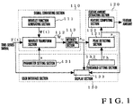
- Fig. 1 is a view showing the arrangement of a data conversion apparatus according to the first embodiment.
- this data conversion apparatus is comprised of a signal converting section 110, a feature amount extracting section 120 for extracting a feature from the signal output from the signal converting section 110, and a user interface section 130 for, for example, setting a parameter for the signal converting section 110 and setting a threshold for the feature amount extracting section 120.
- the signal converting section 110 will be described in detail first.
- the signal converting section 110 is comprised of a wavelet function generating section 111, wavelet transform section 112, and intensity computing section 113.
- the wavelet function generating section 111 generates a complex type wavelet serving as a basic function for a wavelet transform.
- a typical complex type wavelet transform a Gabor wavelet function is available.
- the wavelet transform section 112 performs a wavelet transform of the time-series signal input by an input means or the like (not shown) by using the complex type wavelet function generated by the wavelet function generating section 111.
- the wavelet transform section 112 performs a wavelet transform of the input time-series signal by using the complex type wavelet function generated by the wavelet function generating section 111 on the basis of a scale parameter corresponding to the frequency set by the user interface section 130. In this case, nonorthogonal wavelet transform is performed.
- the feature amount extracting section 120 will be described in detail next.
- the feature amount extracting section 120 is comprised of a peak detecting section 121 and feature computing section 122.
- the peak detecting section 121 detects the maximum value (peak) of a frequency distribution for every unit time in accordance with the wavelet intensity signal output from the intensity computing section 113.
- the peak detecting section 121 detects the peaks (maximum values) of the frequency intensity distributions at intervals of unit times (predetermined time intervals).
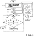
- the number of scale parameters a is set to a maximum value M of i in step S1. That is, the number of divisions of the frequency axis (scale) of the time-frequency information obtained by the wavelet transform is set.
- the number of shift parameters b is set to a maximum value N of j. That is, the number of divisions of the time axis (shift) of the time-frequency information obtained by the wavelet transform is set.
- a threshold is set to Th. This threshold is set by the user interface section 130 to prevent detection of a negligibly small peak that can be produced by a computation error or the like.
- step S2 j is set to 1.
- step S3 i is set to 1.
- step S4 it is checked whether i is larger than 1 and smaller than M. It is assumed that in the time-frequency information obtained as a result of the wavelet transform, no intensity peak appears at the minimum and maximum values of scale (frequency). This determination processing is performed to omit the above case.
- step S6 it is checked whether an intensity A(i, j) at the frequency at a given time is higher than a preset threshold Th. In addition, it is checked whether the intensity A(i, j) is higher than an intensity A(i-1, j). Furthermore, it is checked whether the intensity A(i, j) is higher than an intensity A(i+1, j).
- step S8 1 is added to i.
- step S9 it is checked whether i is larger than M. If it is determined in step S9 that i is not larger than M, steps S4 to S8 are repeated. If it is determined in step S9 that i is larger than M, the flow advances to step S10 to add 1 to j.
- step S11 it is checked whether j is larger than N. If it is determined in step S11 that j is not larger than N, steps S3 to S10 are repeated. If it is determined in step S11 that j is larger than N, the processing is terminated.
- a peak intensity is represented by 1 and an intensity that is not a peak is represented by 0, thereby detecting a peak as a binary value and obtaining a frequency distribution peak signal
- the feature computing section 122 then computes feature amounts such as a frequency, occurrence time, and duration from the detected frequency distribution peak signal for each unit time.
- the user interface section 130 is comprised of a parameter setting section 131, threshold setting section 132, and display section 133.
- the parameter setting section 131 sets a scale parameter for the wavelet transform section 112 in correspondence with a frequency.
- the threshold setting section 132 sets a threshold used by the peak detecting section 121 to prevent detection of a negligibly small peak that is produced due to a computation error or the like.
- the display section 133 displays the wavelet intensity signal output from the signal converting section 110, the frequency distribution peak signal obtained by the feature amount extracting section 120, and the like.
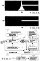
- Fig. 3 shows distribution charts indicating the output results of the wavelet intensity signal and frequency distribution peak signal displayed on the display section 133.
- Fig. 3(a) shows the wavelet intensity signal obtained as a result of the wavelet transform.
- Fig. 3(b) shows the frequency distribution peak signal.
- the abscissa represents the time; and the ordinate (scale), the frequency.
- the second embodiment of the present invention will be described below.
- the above data conversion apparatus is applied to abnormality control detection in an air-conditioner.
- the second embodiment additionally has a hunting determining section 401 and control parameter setting section 402.
- the data conversion apparatus of the second embodiment is comprised of the hunting determining section 401 and control parameter setting section 402, in addition to a signal converting section 110, a feature amount extracting section 120 for extracting a feature from the signal output from the signal converting section 110, a user interface section 130 for setting a parameter for the signal converting section 110 and a threshold for the feature amount extracting section 120.
- the signal converting section 110 is comprised of the wavelet function generating section 111, wavelet transform section 112, and intensity computing section 113.
- the feature amount extracting section 120 is comprised of a peak detecting section 121 and feature computing section 122.
- the user interface section 130 is comprised of a parameter setting section 131, threshold setting section 132, and display section 133.
- a control parameter set at the time of installation may become an improper value due to a change in the performance of the air-conditioner over time.
- control of the air-conditioner becomes unstable, and inconveniences such as hunting, i.e., variations in temperature in the temperature-controlled room in short cycles, occur.
- This hunting reflects the operation state of the air-conditioner. The occurrence of hunting will waste energy or make the user uncomfortable.
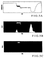
- Fig. 5 shows a temperature detection result (a) in an air-conditioned room, a wavelet intensity distribution (b) obtained by performing a wavelet transform of the result, and a result (c) obtained by extracted from the wavelet transform result using the feature amount extracting section 120.
- the abscissa represents the time; and the ordinate (scale), the frequency.
- the above hunting occurs in a given time zone.
- the hunting appears as vibration components.
- Fig. 5(c) only the vibration components can be extracted in the same manner as in the first embodiment described above.
- the hunting determining section 401 determines the state of hunting indicated by the extracted feature amount on the basis of the frequency, occurrence time, duration, amplitude, and the like.
- the control parameter setting section 402 computes an optimal air-conditioner control value suited to each device in air-conditioning equipment or an environment for an air-conditioning target, and sets the control value in the air-conditioner.
- this embodiment can perform hunting detection for each of a plurality of devices without missing this state. This makes it possible to solve the problem of hunting.
- the third embodiment of the present invention will be described below.
- the above data conversion apparatus is applied to abnormality diagnosis of a rotating device.
- the third embodiment additionally has a normal signal holding section 601, abnormality determining section 602, and alarm output section 603.
- the data conversion apparatus of the third embodiment has the normal signal holding section 601, abnormality determining section 602, and alarm output section 603, in addition to a signal converting section 110, a feature amount extracting section 120 for extracting a feature from the signal output from the signal converting section 110, and a user interface section 130 for setting a parameter for the signal converting section 110 and a threshold for the feature amount extracting section 120.
- the signal converting section 110 is comprised of a wavelet function generating section 111, wavelet transform section 112, and intensity computing section 113.
- the feature amount extracting section 120 is comprised of a feature amount extracting section 120, peak detecting section 121, and feature computing section 122.
- the user interface section 130 is comprised of a parameter setting section 131, threshold setting section 132, and display section 133.
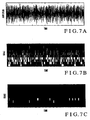
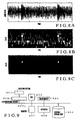
- Fig. 7 shows the vibration waveform (a) of the rotating member during normal operation of the rotating device, the wavelet intensity signal (b), and the result (c) extracted by the feature amount extracting section 120 from the wavelet transform result.
- Fig. 8 shows the vibration waveform (a) of the rotating member at the time of occurrence of abnormality in the rotating device, the wavelet intensity signal (b), and the result (c) extracted by the feature amount extracting section 120 from the wavelet transform result.
- the feature amount in a normal state obtained by the feature amount extracting section 120 is stored in the normal signal holding section 601 in advance.
- the abnormality determining section 602 can determine abnormality by comparing the feature amount obtained at the time of occurrence of abnormality with the feature amount in the normal state.
- the alarm output section 603 outputs an alarm to make it possible to repair the device before a failure. As described above, even if abnormality due to the damage caused in the bearing is small, the abnormality can be reliably detected before the abnormality leads to a failure/stop.
- this embodiment includes the signal converting section 110 and feature amount extracting section 120.
- the operations of these sections may be executed by a CPU.
- an A/D converting section 902 converts the time-series signal obtained by a detecting section 901 into a digital signal.
- a CPU 903 performs a wavelet transform of this converted signal to form a wavelet transform signal developed in a time-frequency domain, computes the intensity of the signal, and detects the maximum value (peak) of a frequency distribution per unit time by using the output wavelet intensity signal.
- the CPU 903 performs the above series of operations in accordance with the program developed in a main memory 904 connected to a bus 903a.
- the program developed in the main memory 904 is stored in an external storage unit 905.
- the wavelet function used for a wavelet transform may be stored in the external storage unit 905 in advance.
- a parameter and threshold may be set with a keyboard 906. An obtained frequency distribution peak signal or the like is displayed on a monitor 907.
- wavelet transform is performed by using the complex type wavelet transform (Gabor wavelet function) represented by equations (2).
- the present invention is not limited to this.
- wavelet transforms can be roughly classified into orthogonal wavelet transforms and nonorthogonal wavelet transforms.
- a wavelet transform used in the above embodiment a nonorthogonal, complex type wavelet function is used.
- a nonorthogonal wavelet transform may be performed by using either a complex type wavelet function as described above or a real number type wavelet function as will be described later.
- a complex type wavelet function such as a Gabor function or the like as described above is used for a nonorthogonal wavelet function, since an intensity can be obtained by computing the absolute value of the wavelet transform result, a peak can be directly detected from the intensity.
- This wavelet function includes a Daubecies function, Harr function, Meyer function, Symlet function, spline function, Coiflet function, and the like.
- characteristic high-frequency components are extracted.
- the present invention is not limited to this.
- Characteristic low-frequency components that hide in high-frequency noise can be extracted by the present invention.
Landscapes
- Engineering & Computer Science (AREA)
- Physics & Mathematics (AREA)
- Mathematical Physics (AREA)
- General Physics & Mathematics (AREA)
- Pure & Applied Mathematics (AREA)
- Mathematical Optimization (AREA)
- Mathematical Analysis (AREA)
- Computational Mathematics (AREA)
- Data Mining & Analysis (AREA)
- Theoretical Computer Science (AREA)
- Algebra (AREA)
- Databases & Information Systems (AREA)
- Software Systems (AREA)
- General Engineering & Computer Science (AREA)
- Complex Calculations (AREA)
Applications Claiming Priority (3)
| Application Number | Priority Date | Filing Date | Title |
|---|---|---|---|
| JP20677597A JP3648023B2 (ja) | 1997-07-31 | 1997-07-31 | データ変換装置およびプログラム記憶媒体 |
| JP20677597 | 1997-07-31 | ||
| PCT/JP1998/003425 WO1999006921A1 (en) | 1997-07-31 | 1998-07-31 | Data conversion method, data converter, and program storage medium |
Publications (2)
| Publication Number | Publication Date |
|---|---|
| EP1001352A1 true EP1001352A1 (de) | 2000-05-17 |
| EP1001352A4 EP1001352A4 (de) | 2008-08-06 |
Family
ID=16528889
Family Applications (1)
| Application Number | Title | Priority Date | Filing Date |
|---|---|---|---|
| EP98935310A Ceased EP1001352A4 (de) | 1997-07-31 | 1998-07-31 | Datenkovertierungsverfahren, datenumwandler und programmspeichermedium |
Country Status (5)
| Country | Link |
|---|---|
| US (1) | US6281814B1 (de) |
| EP (1) | EP1001352A4 (de) |
| JP (1) | JP3648023B2 (de) |
| CN (1) | CN1192319C (de) |
| WO (1) | WO1999006921A1 (de) |
Families Citing this family (10)
| Publication number | Priority date | Publication date | Assignee | Title |
|---|---|---|---|---|
| JP3730435B2 (ja) * | 1999-03-26 | 2006-01-05 | 株式会社東芝 | 波形信号解析装置 |
| US6448909B1 (en) * | 2000-01-28 | 2002-09-10 | The United States Of America As Represented By The Secretary Of The Navy | Analog continuous wavelet transform circuit |
| KR100772669B1 (ko) * | 2001-04-04 | 2007-11-02 | 다이니폰 인사츠 가부시키가이샤 | 원편광 추출 광학 소자의 제조 방법과, 원편광 추출 광학소자 및, 이를 구비한 편광 광원 장치 및 액정 표시 장치 |
| AUPR863001A0 (en) * | 2001-11-01 | 2001-11-29 | Inovatech Limited | Wavelet based fraud detection |
| JP4218824B2 (ja) * | 2002-11-13 | 2009-02-04 | 隆之 大河内 | 木材の年輪箇所検出方法および年輪幅計測方法 |
| JP5606107B2 (ja) * | 2010-03-10 | 2014-10-15 | 三菱電機株式会社 | 基準値作成装置及び基準値作成方法 |
| US9141872B2 (en) * | 2013-09-11 | 2015-09-22 | Digitalglobe, Inc. | Automated and scalable object and feature extraction from imagery |
| KR102174553B1 (ko) * | 2017-12-22 | 2020-11-05 | 미쓰비시덴키 가부시키가이샤 | 음향 계측 시스템 및 파라미터 생성 장치 |
| JP6985180B2 (ja) * | 2018-02-27 | 2021-12-22 | ファナック株式会社 | 数値制御装置 |
| CN119167214B (zh) * | 2024-08-06 | 2025-06-13 | 沈阳航空航天大学 | 一种基于小波变换、二阶差分与1d-lbp的轴承复合故障识别方法 |
Family Cites Families (8)
| Publication number | Priority date | Publication date | Assignee | Title |
|---|---|---|---|---|
| JP3744950B2 (ja) | 1994-03-30 | 2006-02-15 | オリンパス株式会社 | データ解析装置 |
| JPH0883265A (ja) | 1994-09-13 | 1996-03-26 | Toshiba Corp | 振動信号解析装置 |
| US5619998A (en) * | 1994-09-23 | 1997-04-15 | General Electric Company | Enhanced method for reducing ultrasound speckle noise using wavelet transform |
| JPH08177530A (ja) | 1994-12-27 | 1996-07-09 | Toshiba Corp | ガスタービンの異常検知装置 |
| JP3251799B2 (ja) | 1995-02-13 | 2002-01-28 | 三菱電機株式会社 | 機器の診断装置 |
| JPH08329046A (ja) | 1995-05-31 | 1996-12-13 | Toshiba Corp | ウェーブレット変換を用いた信号解析装置 |
| US5821882A (en) * | 1995-08-31 | 1998-10-13 | Yamatake-Honeywell Co., Ltd. | Data conversion method and apparatus |
| US5802369A (en) * | 1996-04-22 | 1998-09-01 | The United States Of America As Represented By The Secretary Of The Navy | Energy-based wavelet system and method for signal compression and reconstruction |
-
1997
- 1997-07-31 JP JP20677597A patent/JP3648023B2/ja not_active Expired - Fee Related
-
1998
- 1998-07-31 CN CNB988078279A patent/CN1192319C/zh not_active Expired - Fee Related
- 1998-07-31 WO PCT/JP1998/003425 patent/WO1999006921A1/ja not_active Ceased
- 1998-07-31 EP EP98935310A patent/EP1001352A4/de not_active Ceased
- 1998-07-31 US US09/485,042 patent/US6281814B1/en not_active Expired - Lifetime
Non-Patent Citations (9)
| Title |
|---|
| DAVID C ROBERTSON ET AL: "WAVELETS AND ELECTROMAGNETIC POWER SYSTEM TRANSIENTS", IEEE TRANSACTIONS ON POWER DELIVERY, IEEE SERVICE CENTER, NEW YORK, NY, US, vol. 11, no. 2, 1 April 1996 (1996-04-01), pages 1050-1057, XP011049126, ISSN: 0885-8977, DOI: DOI:10.1109/61.489367 * |
| PENG Z K ET AL: "Application of the wavelet transform in machine condition monitoring and fault diagnostics: a review with bibliography" MECHANICAL SYSTEMS AND SIGNAL PROCESSING, vol. 18, no. 2, March 2004 (2004-03), pages 199-221, XP002485750 * |
| SASAOKA HIDEKI ET AL: "Air-conditioning fault detection using wavelet analysis", SAVEMATION REVIEW - SAVNG BY AUTOMATION REVIEW, YAMATAKE HONEYWELL KABUSHIKI GAISHA, TOKYO, JP, vol. 17, no. 2, 1999, pages 34-38, XP008116469, ISSN: 0289-4041 -& SASAOKA HIDEKI ET AL: "Air-conditioning fault detection using wavelet analysis - English translation", SAVEMATION REVIEW - SAVNG BY AUTOMATION REVIEW, YAMATAKE HONEYWELL KABUSHIKI GAISHA, TOKYO, JP, vol. 17, no. 2, 1 January 1999 (1999-01-01), pages 34-38, XP008116469, ISSN: 0289-4041 * |
| See also references of WO9906921A1 * |
| STASZEWSKI W J ET AL: "Application of the wavelet transform to fault detection in a spur gear" MECHANICAL SYSTEMS AND SIGNAL PROCESSING, vol. 8, no. 3, May 1994 (1994-05), pages 289-307, XP002485749 * |
| WANG W J ET AL: "Application of wavelets to gearbox vibration signals for fault detection" JOURNAL OF SOUND AND VIBRATION, vol. 192, no. 5, May 1996 (1996-05), pages 927-939, XP002485746 * |
| WANG W J ET AL: "Application of wavelets to gearbox vibration signals for fault detection", JOURNAL OF SOUND & VIBRATION, LONDON, GB, vol. 192, no. 5, 1 May 1996 (1996-05-01), pages 927-939, XP002485746, ISSN: 0022-460X, DOI: DOI:10.1006/JSVI.1996.0226 * |
| WANG W J ET AL: "Early detection of gear failure by vibration analysis - I. Calculation of the time-frequency distribution" MECHANICAL SYSTEMS AND SIGNAL PROCESSING, vol. 7, no. 3, May 1993 (1993-05), pages 193-203, XP002485748 * |
| WANG W J ET AL: "Early detection of gear failure by vibration analysis - II. Interpretation of the time-frequency distribution using image processing techniques" MECHANICAL SYSTEMS AND SIGNAL PROCESSING, vol. 7, no. 3, May 1993 (1993-05), pages 205-215, XP002485747 * |
Also Published As
| Publication number | Publication date |
|---|---|
| US6281814B1 (en) | 2001-08-28 |
| WO1999006921A1 (en) | 1999-02-11 |
| CN1265756A (zh) | 2000-09-06 |
| EP1001352A4 (de) | 2008-08-06 |
| CN1192319C (zh) | 2005-03-09 |
| JPH1153342A (ja) | 1999-02-26 |
| JP3648023B2 (ja) | 2005-05-18 |
Similar Documents
| Publication | Publication Date | Title |
|---|---|---|
| EP1264412B1 (de) | Zerlegung und modellierung komplexer signale | |
| US8066486B2 (en) | Method and apparatus for vibration-based automatic condition monitoring of a wind turbine | |
| US8171796B2 (en) | Acoustic emission detector and controller | |
| JP3484665B2 (ja) | 異常判定方法および装置 | |
| JP2003528292A (ja) | 振動解析によるベアリングの状態ベースのモニタリング | |
| US6281814B1 (en) | Data conversion method, data converter, and program storage medium | |
| EP2135144B1 (de) | Maschinenzustandsüberwachung mithilfe von musterregeln | |
| JPH0718746B2 (ja) | 回転体の異常検出装置 | |
| US20080288213A1 (en) | Machine condition monitoring using discontinuity detection | |
| JPWO2004068078A1 (ja) | 状態判定方法と状態予測方法及び装置 | |
| US6324290B1 (en) | Method and apparatus for diagnosing sound source and sound vibration source | |
| WO2020202567A1 (ja) | 振動音響解析方法及び装置と機器異常部位推定方法及び装置 | |
| JPH1123411A (ja) | 異音判定装置及び異音判定方法 | |
| JP3561151B2 (ja) | 異常診断装置および異常診断方法 | |
| KR101752298B1 (ko) | 회전익 진동 기반 건전성 감시 장치 및 이를 이용하는 감시 방법 | |
| JP3452817B2 (ja) | 漏水音探知識別用信号検出装置 | |
| JP4661853B2 (ja) | 障害分析システム、方法、及びプログラム | |
| JPH08334442A (ja) | 衝撃検知方法及び装置 | |
| JPH08110262A (ja) | オンライン回転体診断装置 | |
| JPH10339664A (ja) | 監視装置及び方法 | |
| CN120011730B (zh) | 一种滚动轴承的故障检测方法、装置、设备及介质 | |
| JP2601799B2 (ja) | 軸受破壊予知方法 | |
| JP2002071447A (ja) | パルス音判定方法 | |
| JPH08329046A (ja) | ウェーブレット変換を用いた信号解析装置 | |
| JP3146062B2 (ja) | 診断装置 |
Legal Events
| Date | Code | Title | Description |
|---|---|---|---|
| PUAI | Public reference made under article 153(3) epc to a published international application that has entered the european phase |
Free format text: ORIGINAL CODE: 0009012 |
|
| 17P | Request for examination filed |
Effective date: 20000117 |
|
| AK | Designated contracting states |
Kind code of ref document: A1 Designated state(s): DE FR GB |
|
| A4 | Supplementary search report drawn up and despatched |
Effective date: 20080707 |
|
| 17Q | First examination report despatched |
Effective date: 20080915 |
|
| REG | Reference to a national code |
Ref country code: DE Ref legal event code: R003 |
|
| STAA | Information on the status of an ep patent application or granted ep patent |
Free format text: STATUS: THE APPLICATION HAS BEEN REFUSED |
|
| 18R | Application refused |
Effective date: 20110519 |