EP1001452B1 - Conteneur electroluminescent pour lampe a decharge haute pression et son procede de fabrication - Google Patents
Conteneur electroluminescent pour lampe a decharge haute pression et son procede de fabrication Download PDFInfo
- Publication number
- EP1001452B1 EP1001452B1 EP99922502A EP99922502A EP1001452B1 EP 1001452 B1 EP1001452 B1 EP 1001452B1 EP 99922502 A EP99922502 A EP 99922502A EP 99922502 A EP99922502 A EP 99922502A EP 1001452 B1 EP1001452 B1 EP 1001452B1
- Authority
- EP
- European Patent Office
- Prior art keywords
- end portions
- respective end
- vessel
- main portion
- mold
- Prior art date
- Legal status (The legal status is an assumption and is not a legal conclusion. Google has not performed a legal analysis and makes no representation as to the accuracy of the status listed.)
- Expired - Lifetime
Links
- 238000004519 manufacturing process Methods 0.000 title claims description 28
- 238000000034 method Methods 0.000 claims description 11
- 239000000463 material Substances 0.000 claims description 9
- 230000004323 axial length Effects 0.000 claims description 7
- 238000012856 packing Methods 0.000 claims description 4
- 238000003780 insertion Methods 0.000 claims 2
- 230000037431 insertion Effects 0.000 claims 2
- 230000002035 prolonged effect Effects 0.000 description 8
- 229910052758 niobium Inorganic materials 0.000 description 7
- 239000010955 niobium Substances 0.000 description 7
- GUCVJGMIXFAOAE-UHFFFAOYSA-N niobium atom Chemical compound [Nb] GUCVJGMIXFAOAE-UHFFFAOYSA-N 0.000 description 7
- ZOKXTWBITQBERF-UHFFFAOYSA-N Molybdenum Chemical compound [Mo] ZOKXTWBITQBERF-UHFFFAOYSA-N 0.000 description 6
- 239000011521 glass Substances 0.000 description 6
- 229910052750 molybdenum Inorganic materials 0.000 description 6
- 239000011733 molybdenum Substances 0.000 description 6
- WFKWXMTUELFFGS-UHFFFAOYSA-N tungsten Chemical compound [W] WFKWXMTUELFFGS-UHFFFAOYSA-N 0.000 description 6
- 229910052721 tungsten Inorganic materials 0.000 description 6
- 239000010937 tungsten Substances 0.000 description 6
- 230000002411 adverse Effects 0.000 description 5
- 230000007797 corrosion Effects 0.000 description 5
- 238000005260 corrosion Methods 0.000 description 5
- 238000007789 sealing Methods 0.000 description 5
- 238000002834 transmittance Methods 0.000 description 5
- PNEYBMLMFCGWSK-UHFFFAOYSA-N aluminium oxide Inorganic materials [O-2].[O-2].[O-2].[Al+3].[Al+3] PNEYBMLMFCGWSK-UHFFFAOYSA-N 0.000 description 4
- 238000005266 casting Methods 0.000 description 4
- 230000008646 thermal stress Effects 0.000 description 4
- 239000000919 ceramic Substances 0.000 description 3
- 238000000465 moulding Methods 0.000 description 3
- 239000002002 slurry Substances 0.000 description 3
- VYPSYNLAJGMNEJ-UHFFFAOYSA-N Silicium dioxide Chemical compound O=[Si]=O VYPSYNLAJGMNEJ-UHFFFAOYSA-N 0.000 description 2
- 230000015572 biosynthetic process Effects 0.000 description 2
- 238000000071 blow moulding Methods 0.000 description 2
- 229910010293 ceramic material Inorganic materials 0.000 description 2
- 239000000203 mixture Substances 0.000 description 2
- 238000012986 modification Methods 0.000 description 2
- 230000004048 modification Effects 0.000 description 2
- 230000035699 permeability Effects 0.000 description 2
- 238000009877 rendering Methods 0.000 description 2
- 229920003171 Poly (ethylene oxide) Polymers 0.000 description 1
- 235000021355 Stearic acid Nutrition 0.000 description 1
- 239000011324 bead Substances 0.000 description 1
- 238000005452 bending Methods 0.000 description 1
- 239000011230 binding agent Substances 0.000 description 1
- 238000007664 blowing Methods 0.000 description 1
- 238000010344 co-firing Methods 0.000 description 1
- 230000000694 effects Effects 0.000 description 1
- 239000011888 foil Substances 0.000 description 1
- 230000004927 fusion Effects 0.000 description 1
- 239000000395 magnesium oxide Substances 0.000 description 1
- CPLXHLVBOLITMK-UHFFFAOYSA-N magnesium oxide Inorganic materials [Mg]=O CPLXHLVBOLITMK-UHFFFAOYSA-N 0.000 description 1
- AXZKOIWUVFPNLO-UHFFFAOYSA-N magnesium;oxygen(2-) Chemical compound [O-2].[Mg+2] AXZKOIWUVFPNLO-UHFFFAOYSA-N 0.000 description 1
- 229910052751 metal Inorganic materials 0.000 description 1
- 239000002184 metal Substances 0.000 description 1
- 229920000609 methyl cellulose Polymers 0.000 description 1
- 239000001923 methylcellulose Substances 0.000 description 1
- 235000010981 methylcellulose Nutrition 0.000 description 1
- 239000012778 molding material Substances 0.000 description 1
- QIQXTHQIDYTFRH-UHFFFAOYSA-N octadecanoic acid Chemical compound CCCCCCCCCCCCCCCCCC(O)=O QIQXTHQIDYTFRH-UHFFFAOYSA-N 0.000 description 1
- OQCDKBAXFALNLD-UHFFFAOYSA-N octadecanoic acid Natural products CCCCCCCC(C)CCCCCCCCC(O)=O OQCDKBAXFALNLD-UHFFFAOYSA-N 0.000 description 1
- 239000004033 plastic Substances 0.000 description 1
- 229920003023 plastic Polymers 0.000 description 1
- 239000000843 powder Substances 0.000 description 1
- 239000010453 quartz Substances 0.000 description 1
- 239000003566 sealing material Substances 0.000 description 1
- 239000008117 stearic acid Substances 0.000 description 1
- 238000007666 vacuum forming Methods 0.000 description 1
- 230000000007 visual effect Effects 0.000 description 1
- XLYOFNOQVPJJNP-UHFFFAOYSA-N water Substances O XLYOFNOQVPJJNP-UHFFFAOYSA-N 0.000 description 1
- RUDFQVOCFDJEEF-UHFFFAOYSA-N yttrium(III) oxide Inorganic materials [O-2].[O-2].[O-2].[Y+3].[Y+3] RUDFQVOCFDJEEF-UHFFFAOYSA-N 0.000 description 1
Images


Classifications
-
- H—ELECTRICITY
- H01—ELECTRIC ELEMENTS
- H01J—ELECTRIC DISCHARGE TUBES OR DISCHARGE LAMPS
- H01J61/00—Gas-discharge or vapour-discharge lamps
- H01J61/02—Details
- H01J61/30—Vessels; Containers
-
- H—ELECTRICITY
- H01—ELECTRIC ELEMENTS
- H01J—ELECTRIC DISCHARGE TUBES OR DISCHARGE LAMPS
- H01J9/00—Apparatus or processes specially adapted for the manufacture, installation, removal, maintenance of electric discharge tubes, discharge lamps, or parts thereof; Recovery of material from discharge tubes or lamps
- H01J9/24—Manufacture or joining of vessels, leading-in conductors or bases
- H01J9/26—Sealing together parts of vessels
- H01J9/265—Sealing together parts of vessels specially adapted for gas-discharge tubes or lamps
- H01J9/266—Sealing together parts of vessels specially adapted for gas-discharge tubes or lamps specially adapted for gas-discharge lamps
Definitions
- the present invention relates to a vessel for a high pressure discharge lamp and a method of manufacturing the same.
- the present invention also relates to a high pressure discharge lamp having such a vessel and a method of manufacturing the same.
- Such a vessel is generally classified into two types.
- the vessel according to a first type is called as “integrated type vessel” and has a main portion forming a discharge space and end portions integrated into the main portion.
- the vessel according to a second type is called as “assembled type vessel” and has a main portion and separate end portions which are inserted into the respective openings of the main portion and thereby assembled with the main portion.
- the assembled type vessel cannot be used for a low watt type of high pressure discharge lamp because of a low lamp efficiency due to the heat loss at junctions of the main portion and the respective end portions.
- the assembled type vessel cannot be used for a high pressure discharge lamp either, because lamp efficiency is an important factor even for a middle-high watt type of high pressure discharge lamp. Therefore, when such lamps are to be manufactured, it has been considered necessary to use the integrated type lamp which does not suffer from the above-mentioned disadvantage of the assembled type vessels.
- the transmittance of the lamp is as high as possible, so that at least a central area of the main portion of the vessel should be as thin as possible.
- the mechanical strength of the end portions to be inserted by the respective electrode members is as high as possible, so that the thickness of the end portions should be as large as possible.
- the thickness of the neighborhood is as large as possible to mitigate adverse influence of corrosion and achieve prolonged lifetime.
- main portion has a thickness at the central area which is smaller than at the respective end portions and at the boundary areas between the respective end portions and the main portion, it is possible to manufacture the lamp having a prolonged lifetime as compared to the lamp with a vessel having an entirely uniform thickness.
- a tubular shaped body 1 ( Fig. 1A ) made of a transparent or translucent ceramic material such as alumina is arranged between an upper half 2 and a lower half 3 of the mold, these mold halves 2, 3 are moved toward each other as shown by arrows a and b, respectively, to set the shaped body 1, and a pressure atmosphere such as air is introduced into an opening 4 of the shaped body 1 so as to obtain a blow-molded body 5 ( Fig. 1B ) of the vessel.
- the blow molding process it is possible to manufacture a vessel in which at least the central area of the main portion has a thickness smaller than at the respective end portions and at the boundary areas between the respective end portions and the main portion.
- the opening 4 it is necessary for the opening 4 to have a diameter enough to admit air into the opening 4.
- the inner diameter of the respective end portions it is difficult for the inner diameter of the respective end portions to have a diameter smaller not more than a designated value of 2 mm, for example. Even if it is possible, it is still difficult for the main body of the vessel to keep a necessary inner diameter of 1-15 mm, for example.
- EP-A-443 964 discloses a lamp vessel having the features of the first part of claim 1.
- the vessel according to the present invention is as set out in claim 1.
- At least a central area of the main portion of the vessel has a thickness smaller than at the respective end portions, so that the central area has a relatively high transmittance and the mechanical strength is relatively high when gaps between the respective end portions and the respective electrode members are sealed with glass.
- the light-emitting material tends to be collected and the proceeding of corrosion is fast in a neighborhood of boundary areas between the respective end portions and the main portion, however, because the central areas of the main portion have a thickness smaller than at the boundary areas between the respective end portions and the main portion, the adverse influence of the corrosion is smaller than the case where it has a substantially uniform thickness as a whole.
- the life time of the vessel according to the present invention is prolonged as compared to that of the vessel which has a substantially uniform thickness as a whole and is manufactured by the casting process. Therefore, the lamp having the vessel according to the present invention has a prolonged lifetime.
- the lamp having the vessel As a diameter of the respective electrode members to be inserted into the respective end portions get larger, the heat loss becomes higher when the lamp is operated, and thus the lamp efficiency is aggravated. Such an adverse influence is remarkable especially when the integrated type vessel for low watt is used, and it is desirable to keep the diameter of the respective electrode members at a necessary minimum length.
- the inner diameter of the respective end portions is much larger than the diameter of the respective electrode members, the light-emitting material can easily penetrate into the gaps between the respective end portions and the respective electrode members after manufacturing the lamp, and the color of the light emitted from the lamp may change, for example.
- the gaps should be as small as possible, that is, if the inner diameter of the respective end portions is not much larger than the diameter of the respective electrode members in view of the characteristics (color, efficiency) of the lamp. As a result, the inner diameter of the respective end portions is not more than about 2 mm.
- the vessel according to the present invention is suitable for the low watt (e.g. 10W, 20W, 50W) type of the lamp. It is also suitable for the middle watt (e.g. 70W, 100W, 150W) type of the lamp and the high watt (e.g. 250W, 400W) type of the lamp in which the lamp efficiency is an important factor. However, if the middle or high watt type of the lamp is used for another type of the lamp in which color rendering is an important factor, for example, it is possible to improve the lamp efficiency and the lifetime as compared to the lamp having the vessel whose thickness is substantially uniform as a whole.
- the middle watt type of the lamp e.g. 70W, 100W, 150W
- the high watt e.g. 250W, 400W
- a ratio of an axial length of the respective end portions to the inner diameter of the respective end portions is not less than 4.
- an outer diameter of an area of respective end portions neighboring the main portion should be not more than about 4 mm.
- the lamp according to the present invention is set out in claim 4.
- the lamp according to the present invention has such a vessel, the limitation of the inner diameter of the respective end portions is smaller than that of the conventional vessel, the transmittance of at least the central area of the main portion becomes high, the lifetime of the lamp is prolonged, and good characteristics (color, efficiency) are obtained.
- a ratio of an axial length of the respective end portions to the inner diameter of the respective end portions may be not less than 4.
- an outer diameter of areas of the respective end portions in adjacent to the main portion may be not more than about 4 mm.
- the invention also provides a method of manufacturing a vessel for a high pressure discharge lamp as set out in claim 5.
- the tubular member made of a transparent or translucent material is set into the mold which is air permeable at least locally, the space between the outer face of the tubular member and the inner face of the mold is compressed with at least one portion of the mold being heated or cooled, to thereby bring the tubular member into contact with the mold so that the member has an outer shape which coincides with the inner face of the mold.
- the limitation of the inner diameter of the respective end portions is smaller than that of the conventional vessel, and it is possible to keep the inner diameter of the main portion at not more than 2 mm which cannot be realized in conventional manner.
- the vessel manufactured by the method of the present invention is suitable for the low watt type of the lamp. It is also suitable for the middle watt type of the lamp and the high watt type of the lamp in which the efficiency is an important factor. However, if the middle or high watt type of the lamp is used for another type of the lamp in which the color rendering is an important factor, for example, it is possible to improve the lamp efficiency and the lifetime compared with the lamp having the vessel whose thickness is substantially uniform as a whole.
- the member which has been brought into contact with the mold, is subjected to stretching so that at least a central area of the main portion has a thickness smaller than at the respective end portions and at boundary areas of the respective end portions and the main portion.
- the central area has a high transmittance and a prolonged prolonged.
- an inner diameter of a portion of the member corresponding to the respective end portions is not more than about 2 mm.
- the member, which has been brought into contact with the mold is subjected to stretching so that a ratio of an axial length of the respective end portions to the inner diameter of the respective end portions is larger than 4.
- a ratio of an axial length of the respective end portions to the inner diameter of the respective end portions is larger than 4.
- an outer diameter of the respective end portions in adjacent to the main portions is reduced furthermore after member is molded into a certain shape . More preferably, the outer diameter is not more than about 4 mm. The aggravation of the lamp efficient is prevented in such a way.
- the lamp can be manufactured by inserting the respective electrode members into the respective end portions of the vessel manufactured by the above-mentioned method.
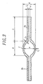
- Fig. 3 is a sectional view for showing an embodiment of the vessel according to the present invention.
- the vessel comprises a substantially spherical main portion 1 forming a discharge space, and end portions 2a, 2b to be inserted respective electrode members.
- the main portion 1 and the end portions 2a, 2b are integrally made of a transparent or translucent material.
- an outer diameter A, an inner diameter a and an axial length B of the main portion 1 are 2-30 mm, 1-15 mm and 2-50 mm, respectively.
- the respective end portions 2a, 2b has an axial length L of 10-20 mm and an inner diameter d of 0.5-2.5 mm. Therefore, a ratio of the length L to the inner diameter d is 4-40. It is preferable to set the ratio within such a range in view of the occurrence of the thermal stress resulting from the difference between the thermal expansion of the respective end portions 2a, 2b and that of the respective electrode members to be inserted.
- a thickness L 1 (0.5-20 mm) of a central area of the main portion 1 is smaller than the thickness L 2 (0.5-30 mm) of the respective end portions 2a, 2b and the thickness L 3 (0.5-30 mm) of boundary areas of the respective end portions 2a, 2b and the main portion 1 by resulting from the pressure difference between an inside and an outside of the vessel.
- the limitation of the inner diameter d is smaller than that of the conventional vessel, and it is possible to keep the inner diameter d at not more than 2 mm which cannot be realized in conventional manner. If the vessel is used for the low watt type of high pressure discharge lamp, it is possible to keep the inner diameter d at 0.2-0.7 mm.
- the central area has a relatively high transmittance and the mechanical strength is relatively high when gaps between the respective end portions 2a, 2b and the respective electrode members are sealed with glass. Further, as the thickness L 2 is smaller than thickness L 2 , an adverse influence of corrosion is reduced. As a result, the lamp having the vessel may have a prolonged lifetime.
- the inner diameter d is not more than 2 mm, it is possible to reduce the gaps between the respective end portions 2a, 2b and the respective electrodes to be inserted after manufacturing the lamp. As a result, the characteristics of the lamp is improved.
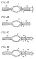
- Figs. 4A to 4D are sectional views for showing modifications of the vessel according to the present invention.
- the vessel as shown in Fig. 4A comprises a main portion 11 and end portions 12a, 12 b, each of which is integrated into the main portion 11 and has a stepped shape.
- the outer diameter D1 of the respective end portions 12a, 12b in adjacent to the main portion 11 should be as small as possible.
- the outer diameter D1 is not more than 1 mm, disadvantages such as a crack may occur when manufacturing the lamp because the vessel cannot have a enough thickness.
- the outer diameter D1 is set to 1-4 mm.
- an outer diameter D2 at the point of the respective end portions 12a, 12b is larger than the outer diameter D1
- the mechanical strength of the respective end portions 12a, 12b is improved.
- the vessel as shown in Fig. 4B comprises a main portion 21 and end portions 22a, 22 b, each of which is integrated into the main portion 21 and has a substantial taper shape.
- an outer diameter D3 at areas of the respective end portions 22a, 22b in adjacent to the main portion 21 is set to 1-4 mm in view of the lamp efficiency and the mechanical strength.
- the vessel as shown in Fig. 4C comprises a main portion 31 and end portions 32a, 32 b, each of which is integrated into the main portion 31 and has a partially stepped shape.
- the respective electrode members to be inserted into the respective end portions 32a, 32b comprises a niobium member, a molybdenum member and a tungsten member
- a region of the respective end portions inserted the respective molybdenum members need to have a greater mechanical strength than that of the respective end portions inserted the respective niobium member and the respective tungsten member. Therefore, an outer diameter D4 or a thickness of a region of the respective end portions inserted the respective molybdenum members is larger than those of the regions of the respective end portions inserted the respective niobium member and the respective tungsten member.
- a thickness at the top of the respective end portions 32a, 32b should be as small as possible. Because the difference between the coefficient of thermal expansion of the transparent or translucent ceramic material such as alumina and that of niobium is comparatively small, it is not necessary to have a comparatively high mechanical strength. Therefore, disadvantages such as a crack hardly occurs when sealing the gaps between the respective end portions and the respective electrode members to be inserted even if a thickness or an outer diameter D5 of a region in adjacent to the top of the respective end portions is smaller than an outer diameter D4.
- the respective electrode members to be inserted into the respective end portions comprises the niobium member, the molybdenum member and the tungsten member.
- an outer diameter D6 of areas of the respective end portions 32a, 32b in adjacent to the main portion 31 is 1-4 mm in view of the lamp efficiency and the mechanical strength.
- the vessel as shown in Fig. 4D comprises a main portion 41 and end portions 42a, 42b, each of which is integrated into the main portion 41 and has a substantial spindle shape.
- the respective electrode members which comprises the niobium member, the molybdenum member and the tungsten member because an outer diameter D7 of a region of the respective end portions inserted the respective molybdenum members is larger than those of regions of the respective end portions inserted the respective niobium member and the respective tungsten member, and an outer diameter D8 of a region in adjacent to a top of the respective end portions is smaller than the outer diameter D7.
- An outer diameter D9 of areas of the respective end portions 42a, 42b in adjacent to the main portion 41 is 1-4 mm in view of the lamp efficiency and the mechanical strength.
- Shapes of end portions as shown in Figs. 3 and 4A-4D are formed by the way as described below such as grinding.
- FIG. 5 is a view for showing an embodiment of the method of manufacturing the vessel according to the present invention
- Fig. 6 is a flow chart for illustrating an embodiment of the method of manufacturing the vessel according to the present invention.
- a mold for forming the vessel in Fig. 5 has a vacuum chamber 53 which is formed by cores 51a, 51b having an air permeability and packings 52a, 52b adhered to the respective cores 51a, 51b. At least the cores 51a, 51b are heated or cooled during the molding of the vessel.
- the respective cores 51a, 51b may be any core which has the air permeability.
- the cores 51a, 51b should be formed by a porous member whose surface has a plurality of holes, by combining a plurality of fine grained beads to each other using a self fusion, a binder or the like, by bending, and gathering one or more wires as well as press molding the gathered wires into a desirable shape, by a porous panting metal, by plastic forming a mesh member into a desirable shape, by forming a plurality of holes onto a molding material as used conventionally, and so on.
- alumina powder having high purity of not less than 99.9 percentage are added 750 ppm of magnesium oxide, 4 weight percentage of methyl cellulose, 2 weight percentage of polyethylene oxide, 5 weight percentage of stearic acid and 23 weight percentage of water, and the resulting mixture is kneaded in a kneader mill for 15 minutes.
- the resulting kneaded mixture is procured to obtain a tubular shaped body (not shown) and the molded body is fixed between the core 51a and the packing 52a as well as the core 51b and packing 52b.
- the fixed body in such a manner is sucked with a vacuum pump 54 and then molded so as to contacting the body onto surfaces of the core 51a, 51b.
- the end portions and the main portion is formed along the molding shape to obtain the integrated type vessel.
- Fig. 7 is a view for showing an embodiment of the high pressure discharge lamp according to the present invention.
- the high pressure lamp includes an outer tube 61 made of quartz glass or hard glass, and a ceramic discharge tube 62 is placed in the outer tube 61 coaxially thereto.
- the ceramic discharge tube 62 comprises a vessel 64 as shown in Fig. 3 , and electrode members 65a, 65b inserted into end portions of the vessel 64 so that the one end of the respective electrode members 65a, 65b is exposed to an inner space formed by a main portion of the vessel 64 and the other thereof is exposed to outside of the vessel.
- the respective electrode members 65a, 65b may have any known structure.
- the ceramic discharge tube 62 is held by the outer tube 61 via two lead wires 66a, 66b.
- the lead wires 66a, 66b are connected to the respective caps 63a, 63b via the respective foils 67a, 67b.
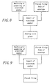
- Fig. 8 shows a flow chart for illustrating a first embodiment of the method of manufacturing the vessel according to the present invention.
- the electrode members are machined or assembled at the same time, before or after a finish fired body of the vessel is obtained in accordance with the manufacturing process as shown in Fig. 6 .
- the respective electrode members are inserted into the respective end portion of the vessel, and the gap between the respective electrode members and the respective end portions is sealed with glass.
- Fig. 9 shows a flow chart for illustrating a second embodiment of the method of manufacturing the vessel according to the present invention.
- the electrode members are machined or assembled at the same time, before or after a finish fired body of the vessel is obtained in accordance with the manufacturing process as shown in Fig. 6 .
- the respective electrode members are inserted into the respective end portion of the vessel, and the respective electrode members and the respective end portions are cofining into an integrated body.
- the main portion of the vessel has the spindle shape, however it may have any other shape such as a tubular or spherical shape. Any other transparent or translucent material such as yttria or quartz may be used instead of alumina.
- the atmospheric pressure between the mold and the molded body may be lower than that of an inner pressure of the molded body instead of sucking with the vacuum pump.
- the end portions may be formed by stretching after the vacuum forming.
- the lamp according to the invention may have the vessel as shown in Figs. 4A-4D instead of that as shown in Fig. 3 . It is also possible to obtain the lamp according to the invention using the know manufacturing process. For example, the gap between the respective electrode members and the respective end portions may be welded instead of sealing with glass or co-firing into the integrated body.
Landscapes
- Engineering & Computer Science (AREA)
- Manufacturing & Machinery (AREA)
- Vessels And Coating Films For Discharge Lamps (AREA)
- Manufacture Of Electron Tubes, Discharge Lamp Vessels, Lead-In Wires, And The Like (AREA)
Claims (11)
- Contenant pour une lampe à décharge haute pression, comprenant une portion principale (1, 11, 21, 31, 41) formant un espace de décharge, et des portions d'extrémité (2a, 2b, 12a, 12b, 22a, 22b, 32a, 32b, 42a, 42b) pour l'insertion d'éléments d'électrode respectifs, ladite portion principale et lesdites portions d'extrémité étant réalisées intégralement en un matériau transparent ou translucide, où au moins une zone centrale de ladite portion principale possède une épaisseur de paroi plus petite qu'aux portions d'extrémité respectives, lesdites portions d'extrémité respectives ayant un diamètre interne non supérieur à 2 mm,
caractérisé en ce qu'aux zones limites entre lesdites portions d'extrémité respectives et ladite portion principale incluant des zones respectives de ladite portion principale adjacente auxdites portions d'extrémité, l'épaisseur de paroi dudit contenant est plus grande qu'à ladite zone centrale de ladite portion principale. - Contenant selon la revendication 1, où le rapport de la longueur axiale des portions d'extrémité respectives audit diamètre interne des portions d'extrémité respectives n'est pas inférieur à 4.
- Contenant selon la revendication 1 ou 2, où le diamètre extérieur des portions d'extrémité respectives aux zones adjacentes à ladite portion principale n'est pas supérieur à environ 4 mm.
- Lampe à décharge haute pression comprenant un contenant selon l'une quelconque des revendications 1 à 3 et des éléments d'électrode insérés dans lesdites portions d'extrémité.
- Procédé de fabrication d'un contenant pour une lampe à décharge haute pression, ledit contenant comprend une portion principale (1, 11, 21, 31, 41) formant un espace de décharge et des portions d'extrémité (2a, 2b etc.) pour l'insertion d'éléments d'électrode respectifs, ladite portion principale et lesdites portions d'extrémité étant intégralement réalisées en un matériau transparent ou translucide;
le procédé comprenant les étapes de: placer un élément tubulaire réalisé en un matériau transparent ou translucide dans un moule, ledit moule (51a, 51b) étant perméable à l'air au moins localement et étant installé dans des garnissages (52a, 52b) définissant une chambre de vide (53) entre eux et ledit moule; et
décompresser ladite chambre de vide (53) et un espace entre une face externe dudit élément tubulaire et une face interne dudit moule, au moins une portion dudit moule étant chauffée ou refroidie, pour amener ainsi ledit élément tubulaire en contact avec ledit moule de telle sorte que ledit élément a une forme extérieure qui coïncide avec ladite face intérieure du moule. - Procédé selon la revendication 5, où ledit élément, qui a été amené en contact avec ledit moule, est soumis à un étirage de sorte qu'au moins une zone centrale de ladite portion principale possède une épaisseur plus petite qu'aux portions d'extrémité respectives et aux zones limites des portions d'extrémité respectives et de ladite portion principale.
- Procédé selon la revendication 5 ou 6, où dans ladite étape de mise en place, un diamètre interne d'une portion dudit élément correspondant aux portions d'extrémité respectives n'est pas supérieur à environ 2 mm.
- Procédé selon l'une quelconque des revendications 5 à 7, où ledit élément, qui a été amené en contact avec ledit moule, est soumis à un étirage de sorte qu'un rapport d'une longueur axiale des portions d'extrémité respectives audit diamètre intérieur des portions d'extrémité respectives est plus grand que 4.
- Procédé selon l'une quelconque des revendications 5 à 8, où un diamètre extérieur des portions d'extrémité respectives adjacentes auxdites portions principales et réduit davantage après que ledit élément a été moulé en une certaine forme.
- Procédé selon la revendication 9, où ledit diamètre extérieur des portions d'extrémité respectives adjacentes auxdites portions principales est réduit pour ne pas être supérieur à 4 mm.
- Procédé de fabrication d'une lampe à décharge haute pression, où les éléments d'électrode respectifs sont insérés dans les portions d'extrémité respectives d'un contenant fabriqué selon l'une quelconque des revendications 5 à 10.
Applications Claiming Priority (3)
| Application Number | Priority Date | Filing Date | Title |
|---|---|---|---|
| JP14561698 | 1998-05-27 | ||
| JP14561698 | 1998-05-27 | ||
| PCT/JP1999/002777 WO1999062103A1 (fr) | 1998-05-27 | 1999-05-26 | Conteneur electroluminescent pour lampe a decharge haute pression et son procede de fabrication |
Publications (3)
| Publication Number | Publication Date |
|---|---|
| EP1001452A1 EP1001452A1 (fr) | 2000-05-17 |
| EP1001452A4 EP1001452A4 (fr) | 2004-10-20 |
| EP1001452B1 true EP1001452B1 (fr) | 2010-02-24 |
Family
ID=15389158
Family Applications (1)
| Application Number | Title | Priority Date | Filing Date |
|---|---|---|---|
| EP99922502A Expired - Lifetime EP1001452B1 (fr) | 1998-05-27 | 1999-05-26 | Conteneur electroluminescent pour lampe a decharge haute pression et son procede de fabrication |
Country Status (7)
| Country | Link |
|---|---|
| US (2) | US6586881B1 (fr) |
| EP (1) | EP1001452B1 (fr) |
| JP (1) | JP3676676B2 (fr) |
| CN (2) | CN100468603C (fr) |
| DE (1) | DE69942052D1 (fr) |
| HU (1) | HU227250B1 (fr) |
| WO (1) | WO1999062103A1 (fr) |
Families Citing this family (16)
| Publication number | Priority date | Publication date | Assignee | Title |
|---|---|---|---|---|
| JP2004513479A (ja) * | 2000-11-01 | 2004-04-30 | コーニンクレッカ フィリップス エレクトロニクス エヌ ヴィ | ランプの製造方法 |
| AU2002231135A1 (en) * | 2000-12-19 | 2002-07-01 | General Electric Company | Method for forming complex ceramic shapes |
| WO2002085590A1 (fr) | 2001-04-17 | 2002-10-31 | Ngk Insulators, Ltd. | Procede de fabrication d'un corps moule, pate de moulage, noyau de moulage, procede de fabrication de ce noyau de moulage, corps creux moule en ceramique, et recipient luminescent |
| US6774566B2 (en) * | 2001-09-19 | 2004-08-10 | Toshiba Lighting & Technology Corporation | High pressure discharge lamp and luminaire |
| US6791267B2 (en) * | 2001-10-02 | 2004-09-14 | Ngk Insulators, Ltd. | High pressure discharge lamps, lighting systems, head lamps for automobiles and light emitting vessels for high pressure discharge lamps |
| JP3907041B2 (ja) * | 2001-10-11 | 2007-04-18 | 日本碍子株式会社 | 高圧放電灯用放電管および高圧放電灯 |
| TW557057U (en) * | 2002-10-09 | 2003-10-01 | Lite On Technology Corp | Scanner |
| US20050194908A1 (en) * | 2004-03-04 | 2005-09-08 | General Electric Company | Ceramic metal halide lamp with optimal shape |
| DE102004024272A1 (de) * | 2004-05-15 | 2005-12-01 | Lanxess Deutschland Gmbh | Pfropfpolymerisathaltige Massen für die Extrusionsverarbeitung |
| US7211954B2 (en) | 2005-03-09 | 2007-05-01 | General Electric Company | Discharge tubes |
| JP2006294581A (ja) * | 2005-03-16 | 2006-10-26 | Toshiba Lighting & Technology Corp | 高圧放電ランプ |
| JP4743847B2 (ja) * | 2005-05-18 | 2011-08-10 | 株式会社小糸製作所 | 自動車用前照灯 |
| JP2007026921A (ja) * | 2005-07-19 | 2007-02-01 | Koito Mfg Co Ltd | 自動車用放電バルブ |
| US7394200B2 (en) * | 2005-11-30 | 2008-07-01 | General Electric Company | Ceramic automotive high intensity discharge lamp |
| WO2008044560A1 (fr) * | 2006-10-05 | 2008-04-17 | Ngk Insulators, Ltd. | Gabarit de maintien pour l'assemblage, dispositif d'assemblage, et procédé de fabrication d'un corps assemblé |
| CN112457031A (zh) * | 2020-12-10 | 2021-03-09 | 郑州凯翔耐火材料有限公司 | 一种低蠕变高铝砖及其制备方法 |
Family Cites Families (18)
| Publication number | Priority date | Publication date | Assignee | Title |
|---|---|---|---|---|
| US3961113A (en) * | 1975-03-03 | 1976-06-01 | Illinois Tool Works Inc. | Thermoplastic preform and heated mandrel constructions |
| AU528293B2 (en) * | 1980-02-06 | 1983-04-21 | Ngk Insulators, Ltd. | Discharge lamp tube |
| US4396857A (en) * | 1980-07-01 | 1983-08-02 | General Electric Company | Arc tube construction |
| GB2085650A (en) * | 1980-09-17 | 1982-04-28 | Matsushita Electronics Corp | High-pressure discharge lamp |
| JPS5823158A (ja) * | 1981-08-04 | 1983-02-10 | Ngk Insulators Ltd | 金属蒸気放電灯用セラミツクチユ−ブの製造法 |
| US4891555A (en) * | 1985-11-15 | 1990-01-02 | General Electric Company | Metal vapor discharge lamps |
| US5153482A (en) * | 1990-02-21 | 1992-10-06 | U.S. Philips Corporation | High-pressure sodium discharge lamp |
| US5144201A (en) * | 1990-02-23 | 1992-09-01 | Welch Allyn, Inc. | Low watt metal halide lamp |
| DE9112690U1 (de) | 1991-10-11 | 1991-12-05 | Patent-Treuhand-Gesellschaft für elektrische Glühlampen mbH, 8000 München | Hochdruckentladungslampe |
| JPH0620649A (ja) * | 1992-07-03 | 1994-01-28 | Toto Ltd | 金属蒸気放電灯の透光性バルブ及びその製造方法 |
| EP0587238B1 (fr) | 1992-09-08 | 2000-07-19 | Koninklijke Philips Electronics N.V. | Lampe à décharge à haute pression |
| JPH07107333A (ja) | 1993-10-01 | 1995-04-21 | Sony Corp | 水平同期回路およびこれを使用したテレビジョン受像機 |
| FR2711014A1 (fr) | 1993-10-04 | 1995-04-14 | Gen Electric | Lampe à quartz à deux extrémités et procédé de fabrication de cette lampe. |
| JPH1081183A (ja) | 1996-09-11 | 1998-03-31 | Ikeda Bussan Co Ltd | エアバッグ装置 |
| JP4316699B2 (ja) * | 1997-07-25 | 2009-08-19 | ハリソン東芝ライティング株式会社 | 高圧放電ランプおよび照明装置 |
| US6137229A (en) * | 1997-09-26 | 2000-10-24 | Matsushita Electronics Corporation | Metal halide lamp with specific dimension of the discharge tube |
| JPH11167896A (ja) | 1997-12-03 | 1999-06-22 | Iwasaki Electric Co Ltd | 金属蒸気放電灯 |
| JP3318250B2 (ja) * | 1997-12-26 | 2002-08-26 | 松下電器産業株式会社 | 金属蒸気放電ランプ |
-
1999
- 1999-05-26 EP EP99922502A patent/EP1001452B1/fr not_active Expired - Lifetime
- 1999-05-26 HU HU0003266A patent/HU227250B1/hu not_active IP Right Cessation
- 1999-05-26 CN CNB2003101024486A patent/CN100468603C/zh not_active Expired - Fee Related
- 1999-05-26 DE DE69942052T patent/DE69942052D1/de not_active Expired - Lifetime
- 1999-05-26 WO PCT/JP1999/002777 patent/WO1999062103A1/fr not_active Ceased
- 1999-05-26 US US09/463,374 patent/US6586881B1/en not_active Expired - Fee Related
- 1999-05-26 JP JP2000551422A patent/JP3676676B2/ja not_active Expired - Fee Related
- 1999-05-26 CN CNB998008486A patent/CN1155987C/zh not_active Expired - Fee Related
-
2002
- 2002-12-27 US US10/331,000 patent/US7041240B2/en not_active Expired - Fee Related
Also Published As
| Publication number | Publication date |
|---|---|
| CN1155987C (zh) | 2004-06-30 |
| EP1001452A4 (fr) | 2004-10-20 |
| US20030096551A1 (en) | 2003-05-22 |
| JP3676676B2 (ja) | 2005-07-27 |
| EP1001452A1 (fr) | 2000-05-17 |
| CN100468603C (zh) | 2009-03-11 |
| CN1577692A (zh) | 2005-02-09 |
| CN1272220A (zh) | 2000-11-01 |
| HU227250B1 (en) | 2010-12-28 |
| US7041240B2 (en) | 2006-05-09 |
| US6586881B1 (en) | 2003-07-01 |
| DE69942052D1 (de) | 2010-04-08 |
| HUP0003266A3 (en) | 2003-04-28 |
| HUP0003266A2 (hu) | 2002-01-28 |
| WO1999062103A1 (fr) | 1999-12-02 |
Similar Documents
| Publication | Publication Date | Title |
|---|---|---|
| EP1001452B1 (fr) | Conteneur electroluminescent pour lampe a decharge haute pression et son procede de fabrication | |
| EP0034056B1 (fr) | Procédé de fabrication d'un tube à décharge en matériau céramique pour lampe à décharge dans une vapeur métallique et tube à décharge fabriqué au moyen de ce procédé | |
| US6126889A (en) | Process of preparing monolithic seal for sapphire CMH lamp | |
| US4800320A (en) | Discharge tube for a high pressure metal vapor discharge lamp and a method of manufacturing the same | |
| JPWO1999062103A1 (ja) | 高圧放電灯用の発光容器及びその製造方法 | |
| JP4709361B2 (ja) | セラミックス発光管 | |
| JP2002164019A (ja) | 高圧放電灯用発光容器 | |
| US6224449B1 (en) | Method of forming lead-in seal in high pressure discharge lamps | |
| KR20010049899A (ko) | 세라믹 아크 튜브 제조 방법 | |
| CA2276763C (fr) | Methode de formage de corps creux en ceramique a formes complexes | |
| US20020072462A1 (en) | Die pressing arctube bodies | |
| KR20020069170A (ko) | 세라믹 아아크관 조립체 및 그 제조 방법 | |
| US6592808B1 (en) | Cermet sintering of ceramic discharge chambers | |
| US7641755B2 (en) | Assembly for forming a ceramic arc discharge vessel and method of manufacture | |
| US20070035250A1 (en) | Ceramic arc tube and end plugs therefor and methods of making the same | |
| JP2005056660A (ja) | 高圧放電ランプ、およびその製造方法 | |
| JPH01186545A (ja) | 高圧放電灯用セラミック発光管 | |
| JP2008519394A (ja) | 放電ランプ、電極、及び、放電ランプの電極部分を製造する方法 | |
| JPH07232970A (ja) | 有底セラミックチューブの製造方法 |
Legal Events
| Date | Code | Title | Description |
|---|---|---|---|
| PUAI | Public reference made under article 153(3) epc to a published international application that has entered the european phase |
Free format text: ORIGINAL CODE: 0009012 |
|
| 17P | Request for examination filed |
Effective date: 20000215 |
|
| AK | Designated contracting states |
Kind code of ref document: A1 Designated state(s): BE DE FR GB NL |
|
| A4 | Supplementary search report drawn up and despatched |
Effective date: 20040908 |
|
| RIC1 | Information provided on ipc code assigned before grant |
Ipc: 7C 04B 35/115 B Ipc: 7H 01J 9/24 B Ipc: 7H 01J 61/30 A |
|
| 17Q | First examination report despatched |
Effective date: 20050209 |
|
| GRAP | Despatch of communication of intention to grant a patent |
Free format text: ORIGINAL CODE: EPIDOSNIGR1 |
|
| GRAS | Grant fee paid |
Free format text: ORIGINAL CODE: EPIDOSNIGR3 |
|
| GRAA | (expected) grant |
Free format text: ORIGINAL CODE: 0009210 |
|
| AK | Designated contracting states |
Kind code of ref document: B1 Designated state(s): BE DE FR GB NL |
|
| REG | Reference to a national code |
Ref country code: GB Ref legal event code: FG4D |
|
| REF | Corresponds to: |
Ref document number: 69942052 Country of ref document: DE Date of ref document: 20100408 Kind code of ref document: P |
|
| REG | Reference to a national code |
Ref country code: NL Ref legal event code: T3 |
|
| PLBE | No opposition filed within time limit |
Free format text: ORIGINAL CODE: 0009261 |
|
| STAA | Information on the status of an ep patent application or granted ep patent |
Free format text: STATUS: NO OPPOSITION FILED WITHIN TIME LIMIT |
|
| 26N | No opposition filed |
Effective date: 20101125 |
|
| PGFP | Annual fee paid to national office [announced via postgrant information from national office to epo] |
Ref country code: DE Payment date: 20130522 Year of fee payment: 15 Ref country code: GB Payment date: 20130522 Year of fee payment: 15 |
|
| PGFP | Annual fee paid to national office [announced via postgrant information from national office to epo] |
Ref country code: BE Payment date: 20130531 Year of fee payment: 15 Ref country code: FR Payment date: 20130531 Year of fee payment: 15 Ref country code: NL Payment date: 20130516 Year of fee payment: 15 |
|
| REG | Reference to a national code |
Ref country code: DE Ref legal event code: R119 Ref document number: 69942052 Country of ref document: DE |
|
| REG | Reference to a national code |
Ref country code: NL Ref legal event code: V1 Effective date: 20141201 |
|
| GBPC | Gb: european patent ceased through non-payment of renewal fee |
Effective date: 20140526 |
|
| PG25 | Lapsed in a contracting state [announced via postgrant information from national office to epo] |
Ref country code: NL Free format text: LAPSE BECAUSE OF NON-PAYMENT OF DUE FEES Effective date: 20141201 |
|
| REG | Reference to a national code |
Ref country code: FR Ref legal event code: ST Effective date: 20150130 |
|
| REG | Reference to a national code |
Ref country code: DE Ref legal event code: R119 Ref document number: 69942052 Country of ref document: DE Effective date: 20141202 |
|
| PG25 | Lapsed in a contracting state [announced via postgrant information from national office to epo] |
Ref country code: DE Free format text: LAPSE BECAUSE OF NON-PAYMENT OF DUE FEES Effective date: 20141202 |
|
| PG25 | Lapsed in a contracting state [announced via postgrant information from national office to epo] |
Ref country code: FR Free format text: LAPSE BECAUSE OF NON-PAYMENT OF DUE FEES Effective date: 20140602 Ref country code: GB Free format text: LAPSE BECAUSE OF NON-PAYMENT OF DUE FEES Effective date: 20140526 |
|
| PG25 | Lapsed in a contracting state [announced via postgrant information from national office to epo] |
Ref country code: BE Free format text: LAPSE BECAUSE OF NON-PAYMENT OF DUE FEES Effective date: 20140531 |