EP1001634A2 - Traitement de signal vidéo, distinction de format d'enregistrement, et reproduction de signal - Google Patents
Traitement de signal vidéo, distinction de format d'enregistrement, et reproduction de signal Download PDFInfo
- Publication number
- EP1001634A2 EP1001634A2 EP99308960A EP99308960A EP1001634A2 EP 1001634 A2 EP1001634 A2 EP 1001634A2 EP 99308960 A EP99308960 A EP 99308960A EP 99308960 A EP99308960 A EP 99308960A EP 1001634 A2 EP1001634 A2 EP 1001634A2
- Authority
- EP
- European Patent Office
- Prior art keywords
- band
- signal
- comparing
- recording format
- recording
- Prior art date
- Legal status (The legal status is an assumption and is not a legal conclusion. Google has not performed a legal analysis and makes no representation as to the accuracy of the status listed.)
- Withdrawn
Links
Images


Classifications
-
- G—PHYSICS
- G11—INFORMATION STORAGE
- G11B—INFORMATION STORAGE BASED ON RELATIVE MOVEMENT BETWEEN RECORD CARRIER AND TRANSDUCER
- G11B20/00—Signal processing not specific to the method of recording or reproducing; Circuits therefor
- G11B20/10—Digital recording or reproducing
- G11B20/12—Formatting, e.g. arrangement of data block or words on the record carriers
-
- H—ELECTRICITY
- H04—ELECTRIC COMMUNICATION TECHNIQUE
- H04N—PICTORIAL COMMUNICATION, e.g. TELEVISION
- H04N9/00—Details of colour television systems
- H04N9/79—Processing of colour television signals in connection with recording
- H04N9/7921—Processing of colour television signals in connection with recording for more than one processing mode
-
- G—PHYSICS
- G11—INFORMATION STORAGE
- G11B—INFORMATION STORAGE BASED ON RELATIVE MOVEMENT BETWEEN RECORD CARRIER AND TRANSDUCER
- G11B15/00—Driving, starting or stopping record carriers of filamentary or web form; Driving both such record carriers and heads; Guiding such record carriers or containers therefor; Control thereof; Control of operating function
- G11B15/02—Control of operating function, e.g. switching from recording to reproducing
- G11B15/026—Control of operating function, e.g. switching from recording to reproducing by using processor, e.g. microcomputer
-
- G—PHYSICS
- G11—INFORMATION STORAGE
- G11B—INFORMATION STORAGE BASED ON RELATIVE MOVEMENT BETWEEN RECORD CARRIER AND TRANSDUCER
- G11B15/00—Driving, starting or stopping record carriers of filamentary or web form; Driving both such record carriers and heads; Guiding such record carriers or containers therefor; Control thereof; Control of operating function
- G11B15/02—Control of operating function, e.g. switching from recording to reproducing
- G11B15/12—Masking of heads; circuits for Selecting or switching of heads between operative and inoperative functions or between different operative functions or for selection between operative heads; Masking of beams, e.g. of light beams
- G11B15/125—Masking of heads; circuits for Selecting or switching of heads between operative and inoperative functions or between different operative functions or for selection between operative heads; Masking of beams, e.g. of light beams conditioned by the operating function of the apparatus
-
- G—PHYSICS
- G11—INFORMATION STORAGE
- G11B—INFORMATION STORAGE BASED ON RELATIVE MOVEMENT BETWEEN RECORD CARRIER AND TRANSDUCER
- G11B20/00—Signal processing not specific to the method of recording or reproducing; Circuits therefor
- G11B20/10—Digital recording or reproducing
-
- G—PHYSICS
- G11—INFORMATION STORAGE
- G11B—INFORMATION STORAGE BASED ON RELATIVE MOVEMENT BETWEEN RECORD CARRIER AND TRANSDUCER
- G11B27/00—Editing; Indexing; Addressing; Timing or synchronising; Monitoring; Measuring tape travel
- G11B27/36—Monitoring, i.e. supervising the progress of recording or reproducing
-
- G—PHYSICS
- G11—INFORMATION STORAGE
- G11B—INFORMATION STORAGE BASED ON RELATIVE MOVEMENT BETWEEN RECORD CARRIER AND TRANSDUCER
- G11B15/00—Driving, starting or stopping record carriers of filamentary or web form; Driving both such record carriers and heads; Guiding such record carriers or containers therefor; Control thereof; Control of operating function
- G11B15/18—Driving; Starting; Stopping; Arrangements for control or regulation thereof
- G11B15/1808—Driving of both record carrier and head
- G11B15/1875—Driving of both record carrier and head adaptations for special effects or editing
-
- G—PHYSICS
- G11—INFORMATION STORAGE
- G11B—INFORMATION STORAGE BASED ON RELATIVE MOVEMENT BETWEEN RECORD CARRIER AND TRANSDUCER
- G11B15/00—Driving, starting or stopping record carriers of filamentary or web form; Driving both such record carriers and heads; Guiding such record carriers or containers therefor; Control thereof; Control of operating function
- G11B15/18—Driving; Starting; Stopping; Arrangements for control or regulation thereof
- G11B15/46—Controlling, regulating, or indicating speed
- G11B15/467—Controlling, regulating, or indicating speed in arrangements for recording or reproducing wherein both record carriers and heads are driven
- G11B15/473—Controlling, regulating, or indicating speed in arrangements for recording or reproducing wherein both record carriers and heads are driven by controlling the speed of the heads
- G11B15/4731—Controlling, regulating, or indicating speed in arrangements for recording or reproducing wherein both record carriers and heads are driven by controlling the speed of the heads control of headwheel rotation
-
- G—PHYSICS
- G11—INFORMATION STORAGE
- G11B—INFORMATION STORAGE BASED ON RELATIVE MOVEMENT BETWEEN RECORD CARRIER AND TRANSDUCER
- G11B20/00—Signal processing not specific to the method of recording or reproducing; Circuits therefor
- G11B20/10—Digital recording or reproducing
- G11B20/12—Formatting, e.g. arrangement of data block or words on the record carriers
- G11B20/1201—Formatting, e.g. arrangement of data block or words on the record carriers on tapes
- G11B20/1211—Formatting, e.g. arrangement of data block or words on the record carriers on tapes with different data track configurations
-
- G—PHYSICS
- G11—INFORMATION STORAGE
- G11B—INFORMATION STORAGE BASED ON RELATIVE MOVEMENT BETWEEN RECORD CARRIER AND TRANSDUCER
- G11B2220/00—Record carriers by type
- G11B2220/90—Tape-like record carriers
- G11B2220/91—Helical scan format, wherein tracks are slightly tilted with respect to tape direction, e.g. VHS, DAT, DVC, AIT or exabyte
-
- G—PHYSICS
- G11—INFORMATION STORAGE
- G11B—INFORMATION STORAGE BASED ON RELATIVE MOVEMENT BETWEEN RECORD CARRIER AND TRANSDUCER
- G11B5/00—Recording by magnetisation or demagnetisation of a record carrier; Reproducing by magnetic means; Record carriers therefor
- G11B5/008—Recording on, or reproducing or erasing from, magnetic tapes, sheets, e.g. cards, or wires
- G11B5/00813—Recording on, or reproducing or erasing from, magnetic tapes, sheets, e.g. cards, or wires magnetic tapes
- G11B5/00847—Recording on, or reproducing or erasing from, magnetic tapes, sheets, e.g. cards, or wires magnetic tapes on transverse tracks
- G11B5/0086—Recording on, or reproducing or erasing from, magnetic tapes, sheets, e.g. cards, or wires magnetic tapes on transverse tracks using cyclically driven heads providing segmented tracks
-
- H—ELECTRICITY
- H04—ELECTRIC COMMUNICATION TECHNIQUE
- H04N—PICTORIAL COMMUNICATION, e.g. TELEVISION
- H04N9/00—Details of colour television systems
- H04N9/79—Processing of colour television signals in connection with recording
- H04N9/80—Transformation of the television signal for recording, e.g. modulation, frequency changing; Inverse transformation for playback
- H04N9/82—Transformation of the television signal for recording, e.g. modulation, frequency changing; Inverse transformation for playback the individual colour picture signal components being recorded simultaneously only
- H04N9/83—Transformation of the television signal for recording, e.g. modulation, frequency changing; Inverse transformation for playback the individual colour picture signal components being recorded simultaneously only the recorded chrominance signal occupying a frequency band under the frequency band of the recorded brightness signal
Definitions
- the present invention relates generally to video signal processing, recording format discriminating, and signal reproducing, and, more particularly, but not exclusively, to a recording format discriminating apparatus for use in a helical scan VTR device capable of discriminating between an analog recording format and a digital recording format of signals recorded on a recording medium.
- the head and the rotary transformer of a recording/reproducing apparatus are made optimum in accordance with the signal format in electromagnetic conversion required for the reproduction of that signal.
- the reproducing head and the rotary transformer dedicated to the format of each of digital and analog signals are used. It should be noted that the rotary transformer in this case is made multichannel for each of the above-mentioned digital and analog signals.
- VTR video tape recorder
- a recording format discriminating apparatus for use on a video tape recorder capable of reproducing a signal recorded on a recording medium in a digital recording format or an analog recording format by one and same head rotary system or a plurality of head rotary systems dedicated to analog recording and digital recording respectively.
- the apparatus comprises: an amplifier, having a capability of automatically controlling a gain of a signal reproduced by one of the head rotary systems, for amplifying the signal to a predetermined level; a first band extracting circuit for extracting a particular narrow frequency band from the amplified signal; a first comparator and detector for detecting by amplification an output of the first band extracting circuit and comparing the detected output with a first reference value; a second comparator and detector for integrating and holding the comparison result output of the first comparator and detector and then comparing the integrated output with a second reference value; and a recording format discriminating circuit for discriminating the recording format of the signal recorded on the recording medium from the comparison result output of the second comparator and detector.
- a digital recording/reproducing apparatus having upward compatibility (in this case, the upward capability is digital recording/reproducing) that allows only the reproduction of conventional analog signals while normally recording and reproducing digital signals is configured for example, the above-mentioned cost increase and the growth of configurational scale cause a significant burden for the manufacturer.
- a signal reproducing apparatus for at least reproducing signals having different band characteristics in electromagnetic conversion from a magnetic recording medium by use of one magnetic head and one rotary transformer, wherein a resonance frequency determined by an equivalent inductance and a resonance capacitance of the magnetic head and the rotary transformer is varied or selected according to formats of signals having different band characteristics in electromagnetic conversion.
- the C/N ratio and amplitude characteristics in each band can be optimized by varying or selecting resonance frequencies and damping quantities according to the signal formats of these signals.
- An 8mm format recording/reproducing apparatus configured to record and reproduce also a digital format signal by switching between the drum rotational speeds and the capstan speeds provides an advantage of allowing, also at digital recording, use of a small-size recording medium (or a cassette) without change and involving additional cost.
- this configuration requires to determine at reproduction whether the recording medium is recorded in analog 8mm format or digital format. For reproduction, selection between these formats must be made manually or automatically.
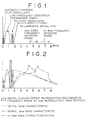
- the format of analog recording (for example, NTSC 8mm video) is characterized by that the frequency allocation of multiplex signal is specified as shown in FIG. 1, providing a gap configuration in which the frequencies of multiplex signals do not overlap one another. Each band varies its occupied bandwidth according to information (video) as time passes but this format prevents the bands from overlapping one another in frequency allocation.
- the frequency spectrum of digital format recording is M-series randomized, being distributed over generally the entire band, changing infrequently in time.
- FIG. 2 shows the aspects of the spectra of both analog recording and digital recording at 8mm video reproduction drum rotational speeds in the case where the ratio of the drum speed at digital recording/reproduction to the drum speed at 8mm video recording/reproduction is 2.5 times as high.
- a digital format signal is recorded in a scrambled form and its spectrum is recorded over a wide band without gap regardless of the information signal (video for example).
- an analog format signal frequency allocations such as video, voice, and tracking and gaps are provided to prevent each frequency band from overlapping one another (refer to FIGS. 1 and 2).
- the presence or absence of the frequency component that provides the gap in the analog format is determined by comparing both signals. If a signal level is found in the gap, it may be determined that this is digital format recording; if not, it may be determined that this is analog format recording. As this gap frequency goes lower, it is more convenient for amplification and detection.
- the gap frequency is equivalent to the band of 1 to 1.4 MHz, a gap between low-frequency converted chrominance frequency band and AFM frequency band for voice signal (the hatched portion shown in FIG. 2) .
- the level ratio between digital and analog in the neighborhood of 1.1 MHz of this gap portion is about 20 dB, which facilitates the discrimination by the detection with a narrow band filter.
- the above-mentioned detection method alone determines that an unrecorded tape is found having no gap frequency component and therefore this tape is recorded in analog fashion. Therefore, it is required to separately determine whether a reproduction tape is with signals recorded or not. For this determination, it is desirable to detect a signal of which level does not change by information at recording.
- the output level of YFM luminance signal
- Mean carrier frequencies are 5 MHz in normal mode and 7 MHz in Hi-8 mode.
- the rotational speed becomes 2.5 times as high, so that the aspect ratio expands to 2.5 times as high and the equivalent reproduction frequency becomes about 12.5 to 17.5 MHz (in 8mm PAL, about 15 to 21 MHz).
- the signal presence/absence detection by use of YFM changing over a wide band causes the problems as mentioned above. Consequently, at digital drum rotation, the detection is made in an equivalent reproduction band (3.5 MHz to 4.6 MHz) which is 2.5 times as high as the AFM signal (voice signal) 1.5 MHz always specified on 8mm format. Detection by filter comparatively broadly around this equivalent reproduction band allows the detection of the YFM signal at 8mm reproduction drum rotation and the AFM signal at digital drum rotation, thereby providing signal detection without especially involving filter switching.
- the signal inputted in the digital/analog discrimination block B is extracted only in its component through a narrow band filter BPF1 5 with the neighborhood of 1.1 MHz being the center.
- the resultant signal is then amplified by an AMP1 7 up to a detectable level to check the difference between digital and analog.
- the amplified signal is then detected by a DET1 8 to be processed by an LPF 8.
- the output signal of the DET1 & LPF 8 is then inputted in a differential comparator COMP1 10 at the "+" (plus) side to be compared with V1 of a reference voltage REF1 9 inputted at the "-" (minus) side.
- the reference signal REF1 9 is set higher than the "+" side input voltage at the time of no signal.
- the comparison output of the differential comparator COMP1 10 is LOW. But, when the detection output over a certain level is inputted at the "+” side, the comparison output goes from LOW to HIGH.
- a HIGH signal is obtained discretely and continuously.
- instantaneous HIGH factors for example, a low-frequency converted chrominance signal, instantaneous sideband expansion of AFM signal, and effects of equivalent reproduction frequency at starting and stop of drum rotation
- the signal is integrated by an integrator INTEGRATE1 11 by use of a time constant of several 10 ms.
- the integrated signal is then inputted in a hold circuit 12.
- This hold circuit 12 is inserted for the purpose that follows. Namely, if the tape travels in different reproduction modes in different formats, servo may be deactivated, resulting in incorrect tracking. In this case, the reproduction is made with different head azimuth angles, so that the RF reproduction output is obtained only once in every several fields, making continuous detection difficult. This phenomenon also occurs at variable-speed reproduction or, if the head is contaminated, at drum rotation starting or end time. Thus, if the RF reproduction drops remarkably, the integration value immediately before this phenomenon is held in the hold circuit 12 to facilitate the detection.
- the hold circuit 12 is turned on/off by a recording signal presence/absence discrimination block A to be described later.
- the output signal of the hold circuit 12 is inputted in a differential comparator COMP2 13 at the "+" side to be compared with V2 voltage of a REF2 14 at the "-" side.
- the output of the COMP1 10 denotes digital format
- the output of the COMP2 13 also goes HIGH.
- This output provides detection signal 1, which is inputted in a microprocessor 15.
- the microprocessor 15 detects the state of this detection signal 1 and such a condition representing presence of data or the state in transmission outputted from the recording signal presence/absence discrimination block A as recording presence and status-in-transition.
- the microprocessor 15 switches the drum rotation and tape travel system to digital reproduction mode.
- the microprocessor 15 also switches the narrow band filter BPF1 5 in the digital/analog discrimination block B to a BPF2 6.
- the subsequent operation will be executed in generally the same manner.
- the RF output including the level fluctuation obtained from the tape head 1 is used without change as the input signal for detection.
- the input signal is amplified by an AMP2 19 via a comparatively broad band filter BPF3 18 around neighborhood of 4.2 MHz.
- the amplified signal is detected by a DET3 20 and processed by an LPF 20.
- the resultant signal is then inputted in a differential comparator COMP3 22 at the "+" side.
- the LPF of the DET3 20 is set to a time constant so that the envelope of the level fluctuation of the RF output is obtained.
- voltage V3 of the REF3 21 is set so that a level drop mainly due to no-recording or at variable-speed reproduction can be detected.
- the output of the COMP3 22 goes LOW when the tape is recorded and HIGH when the tape is not recorded.
- This output signal is processed by an integrator INTEGRATE2 23 to move a large level fluctuation due to single channel head clog (contamination of head gap) or variable-speed reproduction. Then, the integrated signal is compared by a differential comparator COMP4 25 with voltage V4. The COMP4 25 output goes HIGH when the tape is recorded and LOW when the tape is not recorded. This output provides detection signal 2.
- the microprocessor 15 determines the format recorded on this tape as shown in FIG. 4 from the detection signal 1 coming from the digital/analog discrimination block B and the detection signal 2 coming from the recording signal presence/absence discrimination block A.
- the detection signal 1 and the detection signal 2 in the detection signal 1 and the detection signal 2, “0” denotes LOW and “1” denotes HIGH. If the detection signal is "0”, it indicates that the tape is not recorded and the current travel mode is kept unchanged. If the detection signal 2 is "1", the determination of the detection signal 1 is made valid, entering the travel mode suitable for the determined format reproduction.
- the following describes the digital/analog discrimination method used in related-art analog machines (8mm video). If a digital recording format is newly recorded on a recording medium having the same shape (cassette) in addition to conventional analog recording, the digitally recorded portion of the tape cannot be reproduced by a conventional recording/reproducing apparatus. In this case, the tape counter operates (indicating that the tape is recorded), but, if no sync signal at the time of video signal reproduction is given, no reproduced image may be displayed. If this happens, this may be recognized as a machine trouble.
- a digital recording signal is recorded as randomized in frequency. Therefore, if a digital recording signal is reproduced by a conventional analog VTR, it is observed as a noise screen (unless the reproduced video signal is muted). It is difficult for general users to determine whether this video is the reproduction noise of the unrecorded tape or the reproduction signal of digital recording.
- an unrecorded portion of time-series type is arranged in digital recording tape format equivalent to track, the portion corresponding to that unrecorded portion appears at the time of analog reproduction as a band-like noise different in aspect from other portions.
- Execution of the automatic analog/digital discrimination as described above eliminates the inconveniences encountered at the time of reproduction by devices for recording digital and analog signals on a same recording medium (8mm cassette).
- Description of the method of discriminating between analog recording and digital recording on the reproduced screen of a recorded tape on conventional machines (8mm reproducing machines) eliminates the troubles that may unnecessarily confuse users, thereby enhancing user-friendliness.
- the method of detecting through a narrow band filter the gap between the AFM frequency and the low-frequency converted chrominance frequency of 8mm format is characterized by that a large signal level difference for the detection can be obtained, thereby facilitating the discrimination.
- the information about equivalent reproduction signal carrier obtained from the narrow band filter is obtained discretely and continuously at the time of drum starting in other than a drum constant running operation.
- an 8mm format signal because of its isolated frequency allocation, the above-mentioned information can be obtained only discretely and instantaneously.
- this difference is detected by the above-mentioned integrator circuits, thereby allowing early analog/digital discrimination at the time of starting operations such as tape loading.
- FIG. 5A shows the configurations of a magnetic head 101 and a rotary transformer 102
- FIG. 5B shows the configuration of a circuit equivalent to these head and transformer (hereafter referred to as a head rotary system 103)
- FIG.6 shows the configurations of these head 101 and rotary transformer 102 (and the head rotary system 103)
- the amplifier 105 the amplifier 105
- a controller 106 the controller 106
- a resonance capacitance (Ct) a resonance capacitance
- the band in electromagnetic conversion in the head rotary system 103 required at digital recording/reproducing requires 20 MHz or higher.
- the required band in the head rotary system 103 required at analog recording/reproducing is less than 10 MHz even at the tip of white clip in the case of a so-called high-band type 8mm video format for example.
- Head resonance frequency ⁇ 0 occurring in the transmission frequency characteristic of the head rotary system 103 is generally placed at the upper limit of the required band and damped so that C/N (carrier-to-noise) ratio and amplitude phase characteristic are optimized. Consequently, the transmission band of the head rotary system 103 is up to this resonance frequency ⁇ 0 .
- inductance (equivalent converted inductance) obtained as viewed from the entrance of the head amplifier 105 to the head rotary system 103 be Lt
- inductance on the rotor side of the rotary transformer 102 be Lr
- inductance on the stator side be Ls
- turn ratio of the rotary transformer 102 be n
- coupling coefficient k
- head inductance Lh
- the turn ratio of the rotary transformer is 2 to 5. If, for this 8mm video format, the band is to be expanded (or digitized) twice or more as high in the turn ratio n for example, turn ratio becomes 2 to 3. It should be noted that the 2-to-3 turn ratio mentioned above is given because only an integer ratio is allowed as turn ratio. Further, if resonance capacitance Ct is improved, the head resonance frequency ⁇ 0 becomes about 2 times as high.
- the relative speed between tape and head is set 2 times or more as high as the speed at reproduction of a narrow-band signal (an analog signal) only at the time of a wide-band signal (a digital signal), a recording/reproducing apparatus for wide-band signals can be realized with ease.
- the head rotary system 103 can be approximated as shown in FIG. 6. It should be noted that resistance R in the figure is used for damping the head resonance frequency by feedback.
- k in the above-mentioned relation denotes Boltzmann's constant while T denotes absolute temperature. What enclosed in braces ⁇ ⁇ in the above-mentioned relation denotes the total resistance of input converted equivalent noise.
- the first term of the relation denotes a noise source from the amplifier 105.
- the second term denotes a noise source from the damping resistor R. Provided that input converted equivalent noise resistance r shown in FIG. 6 is not included in transmission function.
- the C/N ratio improvement is executed by shifting the head resonance frequency by operating the above-mentioned resonance capacitance Ct.
- the C/N ratio involves a distortion unless the value of the damping resistor R providing optimum amplitude phase characteristic is changed.
- the damping resistor R is incorporated in the amplifier 105 (an integrated circuit IC), the value of the damping resistor R is fixed.
- the value of the damping resistor is fixed, operating the feedback gain Ka of the amplifier 105 according to the change in the resonance capacitor Ct indicates that the above-mentioned relation is established with ease. Namely, at the time of reproducing a narrow-band signal (analog signal), increasing the above-mentioned resonance capacitance Ct to lower the head resonance frequency and, at the same time, increasing the feedback gain Ka can optimize the amplitude phase characteristic. Obviously, in this case, the C/N ratio remains unchanged because the value of the damping resistor R is fixed.
- the optimum amplitude phase characteristic such as described above can be realized by controlling the resonance capacitance Ct and the feedback gain Ka by means of the controller 106.
- a signal voltage induced on the head 101 when a magnetic tape for example is reproduced is multiplied by the rotary transformer 102 by n to provide V1.
- the signal having this signal voltage V1 passes a low-pass filter consisting of the equivalent conversion inductance Lt and the resonance capacitance Ct of the head rotary system 103 and enters the amplifier 105.
- a so-called head resonance frequency caused by the above-mentioned low-pass filter is corrected in amplitude phase characteristic by a feedback loop consisting of the feedback gain Ka, the damping resistor R, and a capacitor Cf, the corrected signal being outputted through an amplifier 153 of a gain K3.
- Gain K2 constituting the feedback gain Ka is controlled by a gain control signal gc coming from the controller 106. For example, as the voltage value of the gain control signal gc lowers, the gain K2 rises, or the feedback gain Ka rises.
- the voltage value of the gain control signal gc is set by resistors R7, R8, and R6 in the controller 106. Whether the gain control signal gc with the voltage value thus set is to be supplied to the amplifier 152 in the amplifier 105 is controlled by turn-on/off of a transistor Q4.
- this additional capacitance Cs is to be used or not is controlled by transistor Q1 and resistor R2, transistor Q2 and resistor R2, and Q3 in the controller 106 so that no effect is caused at the time of recording. For example, when increasing the resonance capacitance Ct to lower the head resonance frequency, the transistors Q1 through Q3 are turned on.
- Operations of a transistor Q4 for controlling the increase in the above-mentioned feedback gain Ka (gain K2) and the transistor Q3 (Q1 to Q3) for controlling the increase in the above-mentioned resonance capacitance Ct (controlling the additional capacitance Cs) are on/off controlled by a mode control signal mc.
- This mode control signal mc is a signal determined according to the formats of signals having different band characteristics in electromagnetic conversion. Namely, in the present embodiment, this mode control signal mc is determined according to whether a signal to be reproduced is a wide-band signal (digital signal) or a narrow-band signal (analog signal).
- the mode control signal mc is LOW (L) at the time of recording or reproduction of a wide-band signal and HIGH (H) at the time of recording or reproduction of a narrow-band signal.
- the transistors Q3 through Q1 and Q4 all turn off (open).
- the mode control signal mc goes HIGH at the time of reproducing a narrow-band signal (analog signal)
- the transistors Q3 through Q1 and Q4 all turn on.
- the transistors Q3 through Q1 turn on, lowering the head resonance frequency by the additional capacitance Cs of the resonance capacitance Ct.
- the transistor Q4 turns on, lowering the voltage of the gain control signal gc to increase the feedback gain Ka. This corrects the amplitude phase characteristic to an optimum level.
- FIG. 6 is circuitry equivalent to one channel with the output of the head rotary system 103 unbalanced. It will be apparent that, in the case of a multi-channel configuration, each channel may also be configured as shown in FIG. 6.
- FIG. 7 shows an example of a circuit configuration equivalent to one channel with the output of the head rotary system 103 balanced. It should be noted that balanced input processing is generally resistant to the elimination of in-phase unnecessary signals.
- components (or elements) similar to those previously described with FIGS. 5A, 5B, and 6 are denoted by the same reference numerals, description of the overlapping portions being skipped.
- a recording amplifier 111 is also illustrated, of which description will be skipped.
- the configurational example of FIG. 7 uses a differential amplifier 121 for the amplifier (the reproducing amplifier 112).
- the differential amplifier 121 is controlled in gain by a gain control signal gc which is similar to that shown in FIG. 6.
- the additional capacitance constituting resonance capacitance Ct is 2Cs and two capacitors are used for this additional capacitance 2Cs.
- a control transistor Q5 is added to the controller 113, thereby preventing balancing from being lost.
- the reproducing amplifier 112 is turned off at recording and mode control signal mc is turned LOW to turn off (open) the transistors Q1, Q5, and Q4 in the controller 113.
- the reproducing amplifier 112 is turned on and, at the time of reproducing a wide-band signal (digital signal) for example, the mode control signal mc is turned LOW to turn off the transistors Q1, Q5, and Q4 in the controller 113.
- the mode control signal mc is turned HIGH to turn on the transistors Q1, Q5, and Q4 in the controller 113.
- the C/N ratio at reproducing a narrow-band signal is improved by use of a minimal additional circuit for the wide-band signal (digital signal) recording/reproducing system.
- FIG. 8 shows the signal reproduction characteristics in the magnetic recording/reproducing apparatus practiced as the present embodiment.
- FIG. 8 indicates the improvement of the C/N ratio in the neighborhood of 10 MHz by about 1.3 dB at the reproduction of a narrow-band signal according to the present embodiment.
Landscapes
- Engineering & Computer Science (AREA)
- Signal Processing (AREA)
- Multimedia (AREA)
- Computer Hardware Design (AREA)
- Digital Magnetic Recording (AREA)
- Recording Or Reproducing By Magnetic Means (AREA)
- Signal Processing For Digital Recording And Reproducing (AREA)
- Television Signal Processing For Recording (AREA)
Applications Claiming Priority (5)
| Application Number | Priority Date | Filing Date | Title |
|---|---|---|---|
| JP10322460A JP2000152158A (ja) | 1998-11-12 | 1998-11-12 | 記録形式判定装置 |
| JP32246098 | 1998-11-12 | ||
| JP34211998A JP3988290B2 (ja) | 1998-12-01 | 1998-12-01 | 信号再生装置 |
| JP34211998 | 1998-12-01 | ||
| JP94211998 | 1998-12-01 |
Publications (2)
| Publication Number | Publication Date |
|---|---|
| EP1001634A2 true EP1001634A2 (fr) | 2000-05-17 |
| EP1001634A3 EP1001634A3 (fr) | 2002-09-25 |
Family
ID=26570828
Family Applications (1)
| Application Number | Title | Priority Date | Filing Date |
|---|---|---|---|
| EP99308960A Withdrawn EP1001634A3 (fr) | 1998-11-12 | 1999-11-10 | Traitement de signal vidéo, distinction de format d'enregistrement, et reproduction de signal |
Country Status (4)
| Country | Link |
|---|---|
| US (1) | US6665488B1 (fr) |
| EP (1) | EP1001634A3 (fr) |
| KR (1) | KR100661252B1 (fr) |
| CN (1) | CN1148724C (fr) |
Families Citing this family (3)
| Publication number | Priority date | Publication date | Assignee | Title |
|---|---|---|---|---|
| JP4277377B2 (ja) * | 1999-08-31 | 2009-06-10 | パナソニック株式会社 | 映像切替装置 |
| JP2005129201A (ja) * | 2003-10-02 | 2005-05-19 | Sony Corp | 磁気記録再生装置 |
| CN104749974B (zh) * | 2013-12-30 | 2017-10-27 | 浙江大华技术股份有限公司 | 一种获取比较电压信号和提取反向控制信号的方法及装置 |
Family Cites Families (8)
| Publication number | Priority date | Publication date | Assignee | Title |
|---|---|---|---|---|
| JPS6012683B2 (ja) * | 1977-03-11 | 1985-04-03 | 株式会社日立製作所 | 映像信号再生回路 |
| JPS6063772A (ja) * | 1983-09-19 | 1985-04-12 | Olympus Optical Co Ltd | デ−タ書込エリア信号発生方法および装置 |
| JPH03130967A (ja) * | 1989-03-31 | 1991-06-04 | Sharp Corp | 磁気再生ヘッドアンプ |
| US6104862A (en) * | 1994-12-19 | 2000-08-15 | Hitachi, Ltd. | Video signal recording and reproducing apparatus compatible with analog and digital video signal recording and reproducing |
| US6178288B1 (en) * | 1995-10-13 | 2001-01-23 | Matsushita Electric Industrial Co., Ltd. | Reproduction device |
| JP3196645B2 (ja) * | 1996-06-24 | 2001-08-06 | 株式会社日立製作所 | 磁気記録再生装置 |
| JPH10255392A (ja) * | 1997-03-14 | 1998-09-25 | Hitachi Ltd | 再生装置 |
| JPH10262204A (ja) * | 1997-03-19 | 1998-09-29 | Hitachi Ltd | 回転ヘッド記録再生装置 |
-
1999
- 1999-11-10 EP EP99308960A patent/EP1001634A3/fr not_active Withdrawn
- 1999-11-11 US US09/439,406 patent/US6665488B1/en not_active Expired - Fee Related
- 1999-11-12 CN CNB991277376A patent/CN1148724C/zh not_active Expired - Fee Related
- 1999-11-12 KR KR1019990050141A patent/KR100661252B1/ko not_active Expired - Fee Related
Also Published As
| Publication number | Publication date |
|---|---|
| EP1001634A3 (fr) | 2002-09-25 |
| KR100661252B1 (ko) | 2006-12-27 |
| CN1257272A (zh) | 2000-06-21 |
| CN1148724C (zh) | 2004-05-05 |
| KR20000035435A (ko) | 2000-06-26 |
| US6665488B1 (en) | 2003-12-16 |
Similar Documents
| Publication | Publication Date | Title |
|---|---|---|
| US6272285B1 (en) | Digital/analog compatible video tape recorder | |
| US5414567A (en) | Magnetic recording and reproducing device | |
| KR920004127B1 (ko) | 자기기록 재생장치 | |
| US5032925A (en) | Circuit for identifying when a reproduced color video signal has been recorded in a high-band or low-band mode | |
| US6665488B1 (en) | Video signal processing apparatus | |
| EP0579198B1 (fr) | Dispositif de contrÔle pour enregistrement magnétique | |
| EP0639826B1 (fr) | Appareil d'enregistrement magnétique avec fonction de test automatique de support d'enregistrement | |
| JPH0614296A (ja) | 映像信号処理装置 | |
| KR100326893B1 (ko) | 자기기록장치 | |
| KR100233539B1 (ko) | 기록특성 보정기능을 갖는 자기기록재생장치 | |
| JP3360457B2 (ja) | 磁気記録再生装置 | |
| KR920007933Y1 (ko) | Vhs/s-vhs방식 vtr에서의 재생신호 이퀄라이저회로 | |
| KR100242648B1 (ko) | 기록특성 보정기능을 갖는 테이프특성 적응기록방식의 자기기록재생장치 | |
| JP3381913B2 (ja) | 映像音声信号記録装置 | |
| JP2000152158A (ja) | 記録形式判定装置 | |
| KR100274215B1 (ko) | 비데오신호의 기록/재생특성을 보정하는 자기기록재생장치 및그 방법 | |
| EP0686966B1 (fr) | Régulateur automatique de courant d'enregistrement d'un enregisteur magnétique | |
| KR0146454B1 (ko) | 녹화취소시 녹화데이터 소거기능을 갖춘 비디오 카세트 레코더 | |
| JP3209416B2 (ja) | 磁気記録装置 | |
| JPS635322Y2 (fr) | ||
| JPH11187355A (ja) | 磁気記録装置 | |
| JPH05258208A (ja) | 磁気記録再生装置 | |
| KR19980085958A (ko) | 비디오 테이프의 정상구간 자동 이동 녹화기능을 갖춘 비디오카세트레코더 | |
| JPH0562340A (ja) | 多重磁気記録再生装置 | |
| JPH0553385U (ja) | 磁気記録再生装置 |
Legal Events
| Date | Code | Title | Description |
|---|---|---|---|
| PUAI | Public reference made under article 153(3) epc to a published international application that has entered the european phase |
Free format text: ORIGINAL CODE: 0009012 |
|
| AK | Designated contracting states |
Kind code of ref document: A2 Designated state(s): AT BE CH CY DE DK ES FI FR GB GR IE IT LI LU MC NL PT SE |
|
| AX | Request for extension of the european patent |
Free format text: AL;LT;LV;MK;RO;SI |
|
| PUAL | Search report despatched |
Free format text: ORIGINAL CODE: 0009013 |
|
| AK | Designated contracting states |
Kind code of ref document: A3 Designated state(s): AT BE CH CY DE DK ES FI FR GB GR IE IT LI LU MC NL PT SE |
|
| AX | Request for extension of the european patent |
Free format text: AL;LT;LV;MK;RO;SI |
|
| 17P | Request for examination filed |
Effective date: 20030227 |
|
| AKX | Designation fees paid |
Designated state(s): DE FR GB |
|
| STAA | Information on the status of an ep patent application or granted ep patent |
Free format text: STATUS: THE APPLICATION IS DEEMED TO BE WITHDRAWN |
|
| 18D | Application deemed to be withdrawn |
Effective date: 20080603 |