EP1002632A2 - Appareil de vulcanisation de pneus. - Google Patents
Appareil de vulcanisation de pneus. Download PDFInfo
- Publication number
- EP1002632A2 EP1002632A2 EP99121955A EP99121955A EP1002632A2 EP 1002632 A2 EP1002632 A2 EP 1002632A2 EP 99121955 A EP99121955 A EP 99121955A EP 99121955 A EP99121955 A EP 99121955A EP 1002632 A2 EP1002632 A2 EP 1002632A2
- Authority
- EP
- European Patent Office
- Prior art keywords
- tire
- mold assembly
- heating medium
- mold
- vulcanizing machine
- Prior art date
- Legal status (The legal status is an assumption and is not a legal conclusion. Google has not performed a legal analysis and makes no representation as to the accuracy of the status listed.)
- Granted
Links
- 230000000712 assembly Effects 0.000 claims abstract description 11
- 238000000429 assembly Methods 0.000 claims abstract description 11
- 238000010438 heat treatment Methods 0.000 claims description 46
- 238000001816 cooling Methods 0.000 description 8
- 230000003028 elevating effect Effects 0.000 description 3
- 238000007599 discharging Methods 0.000 description 2
- 238000000034 method Methods 0.000 description 2
- 239000011324 bead Substances 0.000 description 1
- 238000004519 manufacturing process Methods 0.000 description 1
- 238000003825 pressing Methods 0.000 description 1
- 238000011084 recovery Methods 0.000 description 1
- 238000004073 vulcanization Methods 0.000 description 1
Images


Classifications
-
- B—PERFORMING OPERATIONS; TRANSPORTING
- B29—WORKING OF PLASTICS; WORKING OF SUBSTANCES IN A PLASTIC STATE IN GENERAL
- B29D—PRODUCING PARTICULAR ARTICLES FROM PLASTICS OR FROM SUBSTANCES IN A PLASTIC STATE
- B29D30/00—Producing pneumatic or solid tyres or parts thereof
- B29D30/06—Pneumatic tyres or parts thereof (e.g. produced by casting, moulding, compression moulding, injection moulding, centrifugal casting)
- B29D30/0601—Vulcanising tyres; Vulcanising presses for tyres
-
- B—PERFORMING OPERATIONS; TRANSPORTING
- B29—WORKING OF PLASTICS; WORKING OF SUBSTANCES IN A PLASTIC STATE IN GENERAL
- B29C—SHAPING OR JOINING OF PLASTICS; SHAPING OF MATERIAL IN A PLASTIC STATE, NOT OTHERWISE PROVIDED FOR; AFTER-TREATMENT OF THE SHAPED PRODUCTS, e.g. REPAIRING
- B29C35/00—Heating, cooling or curing, e.g. crosslinking or vulcanising; Apparatus therefor
- B29C35/02—Heating or curing, e.g. crosslinking or vulcanizing during moulding, e.g. in a mould
-
- B—PERFORMING OPERATIONS; TRANSPORTING
- B29—WORKING OF PLASTICS; WORKING OF SUBSTANCES IN A PLASTIC STATE IN GENERAL
- B29C—SHAPING OR JOINING OF PLASTICS; SHAPING OF MATERIAL IN A PLASTIC STATE, NOT OTHERWISE PROVIDED FOR; AFTER-TREATMENT OF THE SHAPED PRODUCTS, e.g. REPAIRING
- B29C33/00—Moulds or cores; Details thereof or accessories therefor
- B29C33/20—Opening, closing or clamping
Definitions
- the present invention relates to a vulcanizing machine of a tire vulcanizing system for vulcanizing a tire, supplying an unvulcanized tire, vulcanizing a tire and discharging a vulcanized tire.
- a tire-vulcanizing machine has two tire molds on the right and left sides thereof so as to increase productivity, and employs a simultaneous mold press type vulcanizing process in which two tires are simultaneously vulcanized with the two tire molds.
- a press mechanism is mounted on a press body, and the right and left tire molds are adapted to be opened or closed at the same time.
- the conventional tire vulcanizing machine described above since the right and left tire molds cannot be opened or closed individually, while no problem occurs when tires which are of the same kind and have the same vulcanizing time are produced, if the tires are of different kind and have vulcanizing times from each other, it is required to adjust an opening or closing operation of the molds for each tire. Therefore, it is difficult to produce the tires efficiently with the conventional tire vulcanizing machine, the conventional tire vulcanizing machine is not suitable for producing a wide variety of tires and for minimizing the stock of products as the member of types of tires to be produced is increasing in recent years.
- the present invention has been achieved in view of the above-mentioned problems associated with the conventional tire vulcanizing machine described above, and it is an object of the present invention to provide a tire vulcanizing machine which can produce a wide variety of tires and can produce the tire efficiently by using a mold opening/closing device of simultaneous mold press type.
- a tire vulcanizing machine in accordance with the present invention has a base frame, a guide column erected on the base frame, an upper movable beam guided by the column so as to move up and down, and at least two connection/disconnection units for connecting or disconnecting the upper movable beam to or from tire mold assemblies, wherein the tire mold assemblies disposed on opposite sides of the column are opened or closed simultaneously or individually.
- the tire vulcanizing machine in accordance with the present invention has the base frame, the guide column erected on the base frame, the upper movable beam guided by the column so as to move up and down, and the two connection/disconnection units for connecting or disconnecting the upper movable beam to or from the tire mold assemblies. Therefore, it is possible to provide the tire- vulcanizing machine which does not reduce its availability even if the frequency of changing molds increases.
- the tire-vulcanizing machine in accordance with the present invention has the base frame, the guide column erected on the base frame, the two upper movable beam guided by the column so as to move up and down, and the two connection/disconnection units for connecting or disconnecting the upper movable beam to or from the tire mold assemblies, wherein the tire mold assemblies disposed on opposite sides of the column are opened or closed simultaneously or individually and each of the tire mold assemblies can be opened or closed individually by using a mold opening/closing unit of simultaneous mold press type. That is, the tire vulcanizing machine in accordance with the present invention can produce tires using a time period for vulcanization suitable for each mold and thus can respond to the production of a wide variety of tires, and further can produce tires more efficiently.
- the tire-vulcanizing machine in accordance with the present invention is provided with a press mechanism in the mold assembly itself, even though the right and left molds are independently operated, it is possible to eliminate the need for providing the machine with an independent opening/closing unit for opening or closing the right and left molds independently. This can reduce the facilities costs.
- FIG. 1 is a front view showing a tire vulcanizing machine of the preferred embodiment in accordance with the present invention
- FIG. 2 is a front view, on an enlarged scale, showing the tire vulcanizing machine of FIG. 1.
- a tire vulcanizing machine 1 of the preferred embodiment in accordance with the present invention has a loader for an unvulcanized tire, an unloader for a vulcanized tire, a tire cooling unit arranged in alignment with a delivery position of the unloader, and an unloader for a cooled tire disposed at the cooling unit, all of which accompany the tire vulcanizing machine 1 and are not shown in the drawings.
- the cooled tire taken out by the unloader is transferred to a suitable place by a tire transfer conveyor arranged outside the drawing.
- a left side unit is in a state in which it is vulcanizing a tire and a right side unit is in a state in which it is being supplied with an unvulcanized tire GT. Also, in a tire vulcanizing machine 1b arranged at the right side, each unit is in a state in which it is vulcanizing a tire.
- the above-mentioned tire vulcanizing machine 1 includes a column 3 erected at the center of an independently arranged base frame 2, an elevating cylinder 4 disposed in the column 3, an upper movable plate (upper movable beam) 7 movable in an up-and-down direction via guide rollers 6 sliding on guide rails 5 fixed to the column 3, a divisible mold operation unit 8 capable of being disconnected, connection/disconnection units 9 for connecting or disconnecting an upper plate assembly M100 of a tire mold assembly M to or from the upper movable plate 7, a bladder operation unit 10 for operating a bladder assembly M300 built-in the tire mold assembly M, a heating chamber C1a of a tire mold C of the tire mold assembly M, and a heating medium supply unit 11 for supplying a heating medium to an upper and a lower heating plates M100A, M200A, wherein the heating medium is supplied into a bladder BL from the bladder operation unit 10.
- the right side machine of the tire vulcanizing machine 1 has been described
- the tire mold assembly M described above is made of the upper plate assembly M100, an upper half mold C1 and a lower half mold C2 of a well-known divisible mold C, a lower plate assembly M200, the bladder BL, the bladder assembly M300, a bracket M400 fixed to the upper plate assembly M100, a plurality of sets of check valves M500 for the upper heating plate M100A fixed to the upper plate assembly M100 and for the heating chamber C1a of the upper half mold C1, a pressure piston plate M200B provided in the lower plate assembly M200, and a special piston valve M600, which is fixed to a suitable portion of the lower plate assembly M200 (for its detail, see Japanese Application Patent No. 9-29746 of the present applicant, which is incorporated herein by reference), for a lower heating plate and an upper heating plate. That is, the tire mold assembly M is fixed on the base frame 2 and the mold thereof is replaced with a fork lift or the like.
- a right portion and a left portion of the upper movable plate 7 of the tire-vulcanizing machine 1 described above are moved up and down at the same time, but all the following units provided in each of the right and the left machines can be operated individually: the loader for the unvulcanized tire, and the unloader for the vulcanized tire, the tire cooling unit, the unloader for the cooled tire, all of which are not shown in the drawing, the divisible mold operation unit 8, the connection/disconnection unit 9 on the upper movable plate 7, the bladder operation unit 10, and the heating medium supply unit 11.
- the upper plate assembly M100 of the tire mold assembly M is not always connected to the upper movable plate 7 nor to the lower plate assembly M200 in the present preferred embodiment, it is a problem how to supply or recover the heating medium to or from the upper plate assembly M100 (the upper heating plate M100A and the heating chamber C1a of the upper half mold C1).
- the upper plate assembly M100 is always connected to the upper movable plate 7, and thus it is essential only that the heating medium introduced into the upper movable plate 7 through a hose or a swivel joint be supplied to the upper plate assembly M100.
- the heating medium is supplied to the upper plate assembly M100 by the heating medium supply unit 11 mounted on the lower plate assembly M200, and while the upper plate assembly M100 is separated from the lower plate assembly M200, a passage for supplying or recovering the heating medium to or from the upper plate assembly M100 is closed to seal the heating medium in the upper plate assembly M100, as shown in FIG. 3.
- the supply or recovery passage described above is closed by the check valve M500.
- the mother pipe side for the heating medium is closed by the special piston valve M600 connected to the check valve M500.
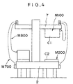
- a structure described below can be employed as a structure for supplying or recovering the heating medium to or from the tire mold assembly M, as shown in FIG. 4.
- the heating medium is introduced into the upper movable plate 7 through a hose or a swivel joint (a first movable part) M700 and then is supplied or recovered to or from the upper plate assembly M100 via a hose or a swivel joint (a second movable part) M800 which has a length nearly equal to the travel of the elevating cylinder 4. If this structure is employed, even when the upper plate assembly M100 is disconnected from the lower plate assembly M200 and even when the upper movable plate 7 is separated from the upper plate assembly M100, the heating medium can continuously be supplied to the upper plate assembly M100, which can lead to a merit of preventing a decrease in the vulcanizing efficiency.
- the unloader of the vulcanized tire (not shown) takes out the tire and places it on the tire cooling unit and starts cooling the tire after the well-known operation.
Landscapes
- Engineering & Computer Science (AREA)
- Mechanical Engineering (AREA)
- Physics & Mathematics (AREA)
- Health & Medical Sciences (AREA)
- Oral & Maxillofacial Surgery (AREA)
- Thermal Sciences (AREA)
- Moulds For Moulding Plastics Or The Like (AREA)
- Heating, Cooling, Or Curing Plastics Or The Like In General (AREA)
Applications Claiming Priority (4)
| Application Number | Priority Date | Filing Date | Title |
|---|---|---|---|
| JP33059198 | 1998-11-20 | ||
| JP33059198 | 1998-11-20 | ||
| JP26975599 | 1999-09-24 | ||
| JP26975599A JP4246862B2 (ja) | 1998-11-20 | 1999-09-24 | タイヤ加硫機 |
Publications (3)
| Publication Number | Publication Date |
|---|---|
| EP1002632A2 true EP1002632A2 (fr) | 2000-05-24 |
| EP1002632A3 EP1002632A3 (fr) | 2000-11-29 |
| EP1002632B1 EP1002632B1 (fr) | 2003-02-12 |
Family
ID=26548898
Family Applications (1)
| Application Number | Title | Priority Date | Filing Date |
|---|---|---|---|
| EP99121955A Expired - Lifetime EP1002632B1 (fr) | 1998-11-20 | 1999-11-09 | Appareil de vulcanisation de pneus. |
Country Status (5)
| Country | Link |
|---|---|
| US (1) | US6338620B1 (fr) |
| EP (1) | EP1002632B1 (fr) |
| JP (1) | JP4246862B2 (fr) |
| KR (1) | KR100348926B1 (fr) |
| DE (1) | DE69905329T2 (fr) |
Cited By (1)
| Publication number | Priority date | Publication date | Assignee | Title |
|---|---|---|---|---|
| EP1658959A3 (fr) * | 2001-08-10 | 2006-06-21 | Bridgestone Corporation | Installation pour la vulcanisation de pneumatiques et procédé utilisant cette installation |
Families Citing this family (9)
| Publication number | Priority date | Publication date | Assignee | Title |
|---|---|---|---|---|
| KR100339379B1 (ko) * | 1999-10-29 | 2002-06-03 | 구자홍 | 바이오칩과 그의 생체 물질 측정장치 및 측정방법 |
| JP5069636B2 (ja) * | 2008-08-11 | 2012-11-07 | 株式会社神戸製鋼所 | タイヤ加硫プレス |
| JP5424727B2 (ja) * | 2009-06-10 | 2014-02-26 | 株式会社ブリヂストン | タイヤの製造方法および装置 |
| JP5627010B2 (ja) * | 2011-06-14 | 2014-11-19 | 株式会社神戸製鋼所 | タイヤ加硫機およびタイヤ加硫方法 |
| CN103737768A (zh) * | 2014-01-20 | 2014-04-23 | 南京佳鼎橡塑机械有限公司 | 双工位抽真空平板硫化机 |
| CN104589550B (zh) * | 2015-01-27 | 2017-02-01 | 广东邦达实业有限公司 | 一种硫化橡胶模自动脱模机构 |
| EP3622098A2 (fr) * | 2017-05-12 | 2020-03-18 | GVD Corporation | Systèmes de dépôt de revêtements sur des surfaces et procédés associés |
| JP6903562B2 (ja) | 2017-12-20 | 2021-07-14 | 株式会社ブリヂストン | タイヤ加硫方法および装置 |
| KR102121885B1 (ko) | 2018-09-07 | 2020-06-11 | 주식회사 한국엔지니어링웍스 | 그린타이어 가류프레스 |
Family Cites Families (10)
| Publication number | Priority date | Publication date | Assignee | Title |
|---|---|---|---|---|
| IT1160163B (it) | 1983-01-12 | 1987-03-04 | Pirelli | Miglioramenti ai dispositivi di vulcanizzazione per pneumatici |
| JPS6248512A (ja) | 1985-08-29 | 1987-03-03 | Mitsubishi Heavy Ind Ltd | タイヤ加硫機の割金型開閉装置 |
| JPS62164506A (ja) | 1986-01-16 | 1987-07-21 | Kobe Steel Ltd | 垂直開閉式タイヤ加硫機 |
| IT1248654B (it) | 1990-05-29 | 1995-01-26 | Pirelli | Pressa di vulcanizzazione con due stampi azionati disgiuntamente fra loro particolarmente per pneumatici di veicoli |
| JP2686375B2 (ja) | 1991-04-23 | 1997-12-08 | 三菱重工業株式会社 | タイヤ製造装置 |
| TW260636B (en) | 1994-05-24 | 1995-10-21 | Kobe Steel Ltd | Tire vulcanizing system |
| JP3004552B2 (ja) | 1994-12-22 | 2000-01-31 | 三菱重工業株式会社 | タイヤ加硫機 |
| JP3254097B2 (ja) | 1995-03-07 | 2002-02-04 | 三菱重工業株式会社 | タイヤ加硫用金型組立体 |
| JP3300735B2 (ja) | 1995-07-14 | 2002-07-08 | 三菱重工業株式会社 | タイヤ加硫用金型組立体 |
| JPH11138544A (ja) | 1997-11-07 | 1999-05-25 | Mitsubishi Heavy Ind Ltd | タイヤ加硫設備 |
-
1999
- 1999-09-24 JP JP26975599A patent/JP4246862B2/ja not_active Expired - Fee Related
- 1999-10-28 KR KR1019990047019A patent/KR100348926B1/ko not_active Expired - Fee Related
- 1999-11-04 US US09/433,960 patent/US6338620B1/en not_active Expired - Fee Related
- 1999-11-09 EP EP99121955A patent/EP1002632B1/fr not_active Expired - Lifetime
- 1999-11-09 DE DE69905329T patent/DE69905329T2/de not_active Expired - Lifetime
Cited By (2)
| Publication number | Priority date | Publication date | Assignee | Title |
|---|---|---|---|---|
| EP1658959A3 (fr) * | 2001-08-10 | 2006-06-21 | Bridgestone Corporation | Installation pour la vulcanisation de pneumatiques et procédé utilisant cette installation |
| US7281916B2 (en) | 2001-08-10 | 2007-10-16 | Bridgestone Corporation | Tire vulcanizing system and tire manufacturing method to be used therefor |
Also Published As
| Publication number | Publication date |
|---|---|
| JP4246862B2 (ja) | 2009-04-02 |
| KR20000035089A (ko) | 2000-06-26 |
| EP1002632A3 (fr) | 2000-11-29 |
| EP1002632B1 (fr) | 2003-02-12 |
| DE69905329D1 (de) | 2003-03-20 |
| JP2000210941A (ja) | 2000-08-02 |
| KR100348926B1 (ko) | 2002-08-14 |
| DE69905329T2 (de) | 2003-07-10 |
| US6338620B1 (en) | 2002-01-15 |
Similar Documents
| Publication | Publication Date | Title |
|---|---|---|
| KR0147182B1 (ko) | 타이어가황기용 분할금형장치 | |
| EP1002632A2 (fr) | Appareil de vulcanisation de pneus. | |
| KR0180924B1 (ko) | 타이어금형 운반장치 | |
| EP1658961B1 (fr) | Procédé de fabrication de pneumatiques utilisant une installation pour la vulcanisation de pneumatiques | |
| JP3872589B2 (ja) | 金型開閉・加硫ステーション | |
| KR100232337B1 (ko) | 타이어 가황기 | |
| KR100359546B1 (ko) | 타이어 가황처리 시스템 및 그 금형 개폐·가황처리스테이션 | |
| CN101827694A (zh) | 横向独立操作的装备有立柱的硫化机 | |
| JP4175444B2 (ja) | タイヤ加硫装置 | |
| JP4191316B2 (ja) | タイヤ加硫設備 | |
| US6582212B1 (en) | Tire vulcanizer and tire vulcanizing equipment equipped with the tire vulcanizer | |
| JP3300735B2 (ja) | タイヤ加硫用金型組立体 | |
| US6719549B1 (en) | Tire vulcanizing equipment | |
| JP2002337148A (ja) | タイヤの製造方法および加硫システム | |
| JP3722865B2 (ja) | タイヤ加硫金型組立体 | |
| JP2003089119A (ja) | タイヤ加硫システム | |
| CN114654770B (zh) | 一种玻璃钢格栅模具液压控制系统 | |
| CN219522753U (zh) | 一种轮胎液压硫化机 | |
| WO1994025241A1 (fr) | Appareil pour decharger des pneus d'une machine a vulcaniser les pneus | |
| JP2000084934A (ja) | タイヤの加硫成形装置および加硫成形方法 | |
| JP4623882B2 (ja) | タイヤ加硫システム | |
| JP2002254152A (ja) | 金型鋳造装置 | |
| JP3272568B2 (ja) | タイヤ金型運搬装置 | |
| JP4909040B2 (ja) | タイヤ加硫設備及びタイヤ加硫方法 | |
| JP2002113720A (ja) | 金型開閉装置およびタイヤ加硫設備 |
Legal Events
| Date | Code | Title | Description |
|---|---|---|---|
| PUAI | Public reference made under article 153(3) epc to a published international application that has entered the european phase |
Free format text: ORIGINAL CODE: 0009012 |
|
| 17P | Request for examination filed |
Effective date: 19991109 |
|
| AK | Designated contracting states |
Kind code of ref document: A2 Designated state(s): DE FR GB |
|
| AX | Request for extension of the european patent |
Free format text: AL;LT;LV;MK;RO;SI |
|
| PUAL | Search report despatched |
Free format text: ORIGINAL CODE: 0009013 |
|
| AK | Designated contracting states |
Kind code of ref document: A3 Designated state(s): AT BE CH CY DE DK ES FI FR GB GR IE IT LI LU MC NL PT SE |
|
| AX | Request for extension of the european patent |
Free format text: AL;LT;LV;MK;RO;SI |
|
| 17Q | First examination report despatched |
Effective date: 20010620 |
|
| AKX | Designation fees paid |
Free format text: DE FR GB |
|
| GRAG | Despatch of communication of intention to grant |
Free format text: ORIGINAL CODE: EPIDOS AGRA |
|
| GRAG | Despatch of communication of intention to grant |
Free format text: ORIGINAL CODE: EPIDOS AGRA |
|
| GRAH | Despatch of communication of intention to grant a patent |
Free format text: ORIGINAL CODE: EPIDOS IGRA |
|
| RIN1 | Information on inventor provided before grant (corrected) |
Inventor name: IRIE, NOBUHIKO, NAGASAKI SHIPYARD & MACHINERY WOR Inventor name: YAMADA, MASATO, NAGASAKI SHIPYARD & MACHINERY WORK |
|
| GRAH | Despatch of communication of intention to grant a patent |
Free format text: ORIGINAL CODE: EPIDOS IGRA |
|
| GRAA | (expected) grant |
Free format text: ORIGINAL CODE: 0009210 |
|
| AK | Designated contracting states |
Designated state(s): DE FR GB |
|
| REG | Reference to a national code |
Ref country code: GB Ref legal event code: FG4D |
|
| REF | Corresponds to: |
Ref document number: 69905329 Country of ref document: DE Date of ref document: 20030320 Kind code of ref document: P |
|
| ET | Fr: translation filed | ||
| PLBE | No opposition filed within time limit |
Free format text: ORIGINAL CODE: 0009261 |
|
| STAA | Information on the status of an ep patent application or granted ep patent |
Free format text: STATUS: NO OPPOSITION FILED WITHIN TIME LIMIT |
|
| 26N | No opposition filed |
Effective date: 20031113 |
|
| PGFP | Annual fee paid to national office [announced via postgrant information from national office to epo] |
Ref country code: DE Payment date: 20101104 Year of fee payment: 12 |
|
| PGFP | Annual fee paid to national office [announced via postgrant information from national office to epo] |
Ref country code: GB Payment date: 20101103 Year of fee payment: 12 |
|
| PGFP | Annual fee paid to national office [announced via postgrant information from national office to epo] |
Ref country code: FR Payment date: 20111118 Year of fee payment: 13 |
|
| GBPC | Gb: european patent ceased through non-payment of renewal fee |
Effective date: 20121109 |
|
| REG | Reference to a national code |
Ref country code: FR Ref legal event code: ST Effective date: 20130731 |
|
| REG | Reference to a national code |
Ref country code: DE Ref legal event code: R119 Ref document number: 69905329 Country of ref document: DE Effective date: 20130601 |
|
| PG25 | Lapsed in a contracting state [announced via postgrant information from national office to epo] |
Ref country code: DE Free format text: LAPSE BECAUSE OF NON-PAYMENT OF DUE FEES Effective date: 20130601 |
|
| PG25 | Lapsed in a contracting state [announced via postgrant information from national office to epo] |
Ref country code: GB Free format text: LAPSE BECAUSE OF NON-PAYMENT OF DUE FEES Effective date: 20121109 Ref country code: FR Free format text: LAPSE BECAUSE OF NON-PAYMENT OF DUE FEES Effective date: 20121130 |