EP1003638B1 - Verfahren und einrichtung zur farbzufuhr - Google Patents
Verfahren und einrichtung zur farbzufuhr Download PDFInfo
- Publication number
- EP1003638B1 EP1003638B1 EP99939342A EP99939342A EP1003638B1 EP 1003638 B1 EP1003638 B1 EP 1003638B1 EP 99939342 A EP99939342 A EP 99939342A EP 99939342 A EP99939342 A EP 99939342A EP 1003638 B1 EP1003638 B1 EP 1003638B1
- Authority
- EP
- European Patent Office
- Prior art keywords
- ink
- feed
- feed according
- ductor roller
- equipment
- Prior art date
- Legal status (The legal status is an assumption and is not a legal conclusion. Google has not performed a legal analysis and makes no representation as to the accuracy of the status listed.)
- Expired - Lifetime
Links
Images

Classifications
-
- B—PERFORMING OPERATIONS; TRANSPORTING
- B41—PRINTING; LINING MACHINES; TYPEWRITERS; STAMPS
- B41F—PRINTING MACHINES OR PRESSES
- B41F31/00—Inking arrangements or devices
- B41F31/02—Ducts, containers, supply or metering devices
- B41F31/022—Ink level control devices
-
- B—PERFORMING OPERATIONS; TRANSPORTING
- B41—PRINTING; LINING MACHINES; TYPEWRITERS; STAMPS
- B41F—PRINTING MACHINES OR PRESSES
- B41F31/00—Inking arrangements or devices
- B41F31/02—Ducts, containers, supply or metering devices
- B41F31/04—Ducts, containers, supply or metering devices with duct-blades or like metering devices
Definitions
- the invention relates to a method and a device for the ink supply of pasty printing inks on printing machines.
- ink feeds on printing presses known (DE-PS 30 30 774), the ink fountain, a duct roller and a plurality of successive along the duct roller, one Contain variable dosing elements forming color gap on the bottom of the ink fountain.
- the pasty printing ink is in the ink box underside including ink metering elements and duct roller formed, open, wedge-shaped ink reservoir.
- the disadvantage of this ink supply is that the ink supply space is very large and therefore different Difficulty changing colors or cleaning. Furthermore, the dosage the amount of ink zones only possible via the ink metering elements.
- a short inking unit with a color metering device is known from DE 38 18 339 A1.
- the Ink metering device consists of a metering system and a pre-metering system.
- the pre-metering system is a conventional ink fountain dosing system.
- the dosing system consists of a Anilox roller against which a doctor is employed for the purpose of metering.
- the anilox roller will contacted by the inking roller of the ink fountain metering system, so that there are two ink supply spaces form. On the one hand, this is the interior of the ink fountain and, on the other hand, a paint storage space between the anilox roller and the ink feed roller.
- Through the gap between the The inking roller and the anilox roller are pre-metered, while the doctor blade finely doses performs. The ink retained by the squeegee is fed back into the ink fountain.
- the object of the invention is to provide a method and a device for ink supply with improved dosage and little cleaning effort.
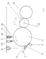
- the inventive method is on the devices shown in Figures 1 and 2 applicable for ink supply.
- a ink fountain 1 in a known open design is assigned a duct roller 2 and Ink fountain contains a plurality of, one after the other, along the duct roller 2 variable color gap forming color metering elements 3 on the underside of the ink fountain 1 (Fig. 1).
- a color metering element 3 is usually assigned to each color zone.
- the ink fountain 1 is designed as an open ink fountain and contains only one Minimum amount of color 4.
- the minimum amount of color means the amount of color that on the function of the ink supply, i.e. for wetting the duct roller and for maintenance a defined hydrodynamic pressure in the ink fountain, is absolutely necessary.
- the surface 5 of the minimum amount of color 4 is assigned a level controller 6, which Fill level or the level of the minimum color quantity 4 is If the specified minimum color level is exceeded, corresponding control steps - increase or decrease the minimum color quantity - initiates or generates warning messages.
- the duct roller 2 is at least one feed system 7 for the amount of consumable ink 8 assigned.
- Consumption color quantity 8 is understood to mean the quantity of color that is used to color the Printing form is necessary for the respective print job, i.e. the amount of consumable ink supplied 8 corresponds to the amount of ink in the inking of the printing form and ultimately is used when applying ink to the substrate.
- a feed system 7 is assigned to each ink zone group.
- a single feed system 7 is traversing according to an embodiment, not shown arranged along the duct roller 2, the level controller 6 expediently is assigned to only one traversing feed system 7.
- the feed system 7 and / or the level controller 6 is advantageously a known one assigned traversing color stirring system.
- Each feed system 7 is connected to a paint supply system, not shown and contains a dosing unit 9 and a pressure switch unit 10.
- the dosing unit is control technology with a device, not shown, for entering Inking unit setting values that are adequate for ink consumption.
- the inking unit settings can usually be made using a known printing plate reader (Scanner) determined or obtained from prepress data (CIP3) or from experience become.
- Scanner printing plate reader
- CIP3 prepress data
- the control of the amount of consumable ink 8 is also via the level query
- Minimum amount of color - increased minimum amount of color means that the amount of consumable ink supplied is too large, a reduction in the quantity of consumable ink is therefore necessary or too low minimum color quantity means too little consumption color quantity supplied, so that is an increase in the amount of consumable ink required - possible.
- the paint supply system can be replaced by a paint supply using cartridges.
- the duct roller 2 is a lifter 11 and this is followed by a friction roller 12 of a known inking unit, not shown.
- the lifter 11 which swings back and forth in the printing operation between the doctor roller 2 and the friction roller 12 is brought into constant contact with both the doctor roller and the friction roller in order to increase the reactivity - quick transport of ink after changing the order into the inking unit - and to improve cleaning.
- washing liquid 13 is applied to the duct roller 2 via a washing device 13.
- a device for ink supply is shown in a closed design.
- the minimum amount of color 4 is in a reduced and closed color storage space 16.
- the minimum amount of ink 4 is not monitored by a level controller 6 but by a pressure switch 14 in the ink supply line 15.
Landscapes
- Inking, Control Or Cleaning Of Printing Machines (AREA)
- Ink Jet (AREA)
Description
- Fig. 1
- eine Einrichtung zur Farbzufuhr in offener Bauart,
- Fig. 2
- eine Einrichtung zur Farbzufuhr in geschlossener Bauart.
Der Duktorwalze 2 ist ein Heber 11 und diesem eine Reibwalze 12 eines nicht dargestellten bekannten Farbwerkes nachgeordnet.
Der im Druckbetrieb zwischen Duktorwalze 2 und Reibwalze 12 hin- und herschwingende Heber 11 wird zur Erhöhung der Reaktionsfähigkeit - schneller Transport von Farbe nach Auftragwechsel in das Farbwerk - und zur Verbesserung der Reinigung in ständigen Berührungskontakt sowohl mit der Duktorwalze als auch mit der Reibwalze gebracht. Zur Reinigung wird auf die Duktorwalze 2 über eine Wascheinrichtung 13 Waschflüssigkeit aufgebracht.
Die Minimalfarbmenge 4 befindet sich dabei in einem verkleinerten und geschlossenen Farbvorratsraum 16.
Die Überwachung der Minimalfarbmenge 4 erfolgt dabei nicht durch einen Niveauregler 6 sondern über einen Druckwächter 14 in der Farbzufuhrleitung 15.
Durch die Aufspaltung der Farbmenge in Minimalfarbmenge und Verbrauchsfarbmenge und die zonenweise Zuführung der Verbrauchsfarbmenge ist eine exaktere Farbdosierung möglich und der Aufwand zur Reinigung bei Auftragwechsel wird minimiert.
- 1
- Farbkasten
- 2
- Duktorwalze
- 3
- Farbdosierelement
- 4
- Minimalfarbmenge
- 5
- Oberfläche
- 6
- Niveauregler
- 7
- Zuführsystem
- 8
- Verbrauchsfarbmenge
- 9
- Dosiereinheit
- 10
- Druckschaltereinheit
- 11
- Heber
- 12
- Reibwalze
- 13
- Wascheinrichtung
- 14
- Druckwächter
- 15
- Farbzufuhrleitung
- 16
- Farbvorratsraum
Claims (21)
- Verfahren zur Farbzufuhr für pastöse Druckfarben mittels eines Farbkastens (1), einer Duktorwalze (2) und einer Mehrzahl von längs der Duktorwalze (2) aufeinanderfolgenden, einen veränderlichen Farbspalt bildenden Farbdosierelementen (3) an der Unterseite des Farbkastens (1), dadurch gekennzeichnet, dass die Menge der Druckfarbe in eine Minimalfarbmenge (4) und eine Verbrauchsfarbmenge (8) unterteilt, die Minimalfarbmenge (4) sich im Farbkasten (1) befindet und die Verbrauchsfarbmenge (8) direkt auf die Duktorwalze (2) aufgebracht wird.
- Verfahren zur Farbzufuhr nach Anspruch 1, dadurch gekennzeichnet, dass die Zufuhr der Verbrauchsfarbmenge (8) farbzonenweise oder farbzonengruppenweise erfolgt.
- Verfahren zur Farbzufuhr nach Anspruch 1, dadurch gekennzeichnet, dass die Zufuhr der Verbrauchsfarbmenge (8) zonenweise oder zonengruppenweise entsprechend des ermittelten Farbverbrauches erfolgt.
- Verfahren zur Farbzufuhr nach Anspruch 3, dadurch gekennzeichnet, dass der Farbverbrauch auf der Grundlage von Farbwerkeinstellwerten ermittelt wird.
- Verfahren zur Farbzufuhr nach Anspruch 3, dadurch gekennzeichnet, dass der Farbverbrauch aus Plattenscannerdaten ermittelt wird.
- Verfahren zur Farbzufuhr nach Anspruch 3, dadurch gekennzeichnet, dass der Farbverbrauch aus Vorstufendaten ermittelt wird.
- Verfahren zur Farbzufuhr nach Anspruch 1, dadurch gekennzeichnet, dass das Niveau der Minimalfarbmenge (4) mittels eines Niveaureglers (6) überwacht wird.
- Verfahren zur Farbzufuhr nach Anspruch 1, dadurch gekennzeichnet, dass bei Auftragende die Zufuhr der Verbrauchsfarbmenge (8) beendet, die Minimalfarbmenge (4) zielgerichtet verbraucht und der Duktorwalze (2) Waschflüssigkeit zugeführt wird.
- Verfahren zur Farbzufuhr nach Anspruch 1, dadurch gekennzeichnet, dass die Zufuhr der Verbrauchsfarbmenge (8) über eine Dosiereinheit (9) und eine Druckschaltereinheit (10) von einer Farbversorgungsanlage erfolgt.
- Verfahren zur Farbzufuhr nach Anspruch 1, dadurch gekennzeichnet, dass die Zufuhr der Verbrauchsfarbmenge (8) über eine Dosiereinheit (3) von einer Farbkartusche erfolgt.
- Verfahren zur Farbzufuhr nach Anspruch 1, dadurch gekennzeichnet, dass die Minimalfarbmenge (4) im offenen Farbkasten (1) enthalten ist.
- Verfahren zur Farbzufuhr nach Anspruch 1, dadurch gekennzeichnet, dass die Minimalfarbmenge (4) in einem abgeschlossenen, verkleinerten Farbvorratsraum (16) enthalten ist.
- Einrichtung zur Farbzufuhr für pastöse Druckfarben mit einem Farbkasten (1), einer Duktorwalze (2) und einer Mehrzahl von längs der Duktorwalze (2) aufeinanderfolgenden, einen veränderlichen Farbspalt bildenden Farbdosierelementen (3) an der Unterseite des Farbkastens (1), dadurch gekennzeichnet, dass dem Farbkasten (1) eine Minimalfarbmenge (4) und der Duktorwalze (2) mindestens ein Zuführsystem (7) zur Zufuhr von Verbrauchsfarbe (8) zugeordnet ist.
- Einrichtung zur Farbzufuhr für pastöse Druckfarben nach Anspruch 13, dadurch gekennzeichnet, dass der Duktorwalze (2) pro Farbzone ein Zuführsystem (7) zur Zufuhr von Verbrauchsfarbe (8) zugeordnet ist.
- Einrichtung zur Farbzufuhr nach Anspruch 13, dadurch gekennzeichnet, dass ein Zuführsystem (7) in einer längs der Duktorwalze (2) traversierenden Einrichtung angeordnet ist.
- Einrichtung zur Farbzufuhr nach Anspruch 13, dadurch gekennzeichnet, dass der Duktorwalze (2) eine Wascheinrichtung (13) zur Zufuhr von Waschflüssigkeit zugeordnet ist.
- Einrichtung zur Farbzufuhr nach Anspruch 13, dadurch gekennzeichnet, dass der Oberfläche (5) der im Farbkasten (1) befindlichen Minimalfarbmenge (4) ein Niveauregler (6) zugeordnet ist.
- Einrichtung zur Farbzufuhr nach Anspruch 13, dadurch gekennzeichnet, dass ein Zuführsystem (7) und ein Niveauregler (6) in einer längs der Duktorwalze (2) traversierenden Einrichtung angeordnet sind.
- Einrichtung zur Farbzufuhr nach Anspruch 18, dadurch gekennzeichnet, dass die ein Zuführsystem (7) und einen Niveauregler (6) enthaltende traversierende Einrichtung identisch mit einer traversierenden Farbrühreinrichtung ist.
- Einrichtung zur Farbzufuhr nach Anspruch 13, dadurch gekennzeichnet, dass das Zuführsystem (7) zur Zufuhr von Verbrauchsfarbe (8) eine mit einer Farbversorgungsanlage verbundene Dosiereinheit (9) einschließlich Druckschaltereinheit (10) enthält.
- Einrichtung zur Farbzufuhr nach Anspruch 13, dadurch gekennzeichnet, dass ein der Duktorwalze (2) nachgeordneter und einer Reibwalze (12) vorgeordneter Heber (11) beim Waschvorgang oder Einlaufvorgang in Berührungskontakt mit der Duktorwalze (2) und der Reibwalze (12) verbringbar ist.
Applications Claiming Priority (3)
| Application Number | Priority Date | Filing Date | Title |
|---|---|---|---|
| DE19826810 | 1998-06-16 | ||
| DE19826810A DE19826810A1 (de) | 1998-06-16 | 1998-06-16 | Verfahren und Einrichtung zur Farbzufuhr |
| PCT/DE1999/001763 WO1999065683A1 (de) | 1998-06-16 | 1999-06-12 | Verfahren und einrichtung zur farbzufuhr |
Publications (2)
| Publication Number | Publication Date |
|---|---|
| EP1003638A1 EP1003638A1 (de) | 2000-05-31 |
| EP1003638B1 true EP1003638B1 (de) | 2002-09-25 |
Family
ID=7871053
Family Applications (1)
| Application Number | Title | Priority Date | Filing Date |
|---|---|---|---|
| EP99939342A Expired - Lifetime EP1003638B1 (de) | 1998-06-16 | 1999-06-12 | Verfahren und einrichtung zur farbzufuhr |
Country Status (4)
| Country | Link |
|---|---|
| US (1) | US6561099B1 (de) |
| EP (1) | EP1003638B1 (de) |
| DE (2) | DE19826810A1 (de) |
| WO (1) | WO1999065683A1 (de) |
Families Citing this family (5)
| Publication number | Priority date | Publication date | Assignee | Title |
|---|---|---|---|---|
| JP4163923B2 (ja) * | 2002-10-01 | 2008-10-08 | 株式会社小森コーポレーション | 凹版印刷機 |
| DE102009018155A1 (de) * | 2009-04-21 | 2010-11-11 | Technotrans Ag | Waschanlage für Druckmaschine |
| CN106218211A (zh) * | 2016-07-20 | 2016-12-14 | 长兴艾飞特科技股份有限公司 | 油印设备 |
| CN107856355A (zh) * | 2017-11-22 | 2018-03-30 | 天津市津东华明纸箱厂 | 一种纸箱快速印图机 |
| DE102019103790A1 (de) * | 2019-02-05 | 2020-08-06 | Koenig & Bauer Ag | Druckwerk und Druckmaschine mit einem Druckwerk |
Family Cites Families (47)
| Publication number | Priority date | Publication date | Assignee | Title |
|---|---|---|---|---|
| FR472535A (de) | 1914-05-20 | |||
| US3730089A (en) * | 1971-06-16 | 1973-05-01 | Itek Corp | Ink monitoring apparatus |
| JPS5133543B2 (de) * | 1972-07-19 | 1976-09-20 | ||
| US3848529A (en) * | 1972-10-24 | 1974-11-19 | Baldwin Gegenheimer Corp | Ink level control system |
| DE2300289C2 (de) * | 1973-01-04 | 1985-01-10 | Mitter & Co, 4815 Schloss Holte | Vorrichtung zum Auftragen flüssiger oder pastöser Farbe für Siebdruckmaschinen |
| US3898929A (en) * | 1973-11-21 | 1975-08-12 | Tor Arild | Hickey picking device for letter press or offset printing presses |
| CH631111A5 (fr) * | 1978-04-07 | 1982-07-30 | Jean Lucien Sarda | Mecanisme d'encrage. |
| WO1979000955A1 (en) * | 1978-04-21 | 1979-11-15 | Baldwin Gegenheimer Corp | Ink level control |
| DE3028025C2 (de) | 1980-07-24 | 1983-04-14 | Miller-Johannisberg Druckmaschinen Gmbh, 6200 Wiesbaden | Verfahren zur Veränderung des Farbflusses durch unterschiedliches Verstellen einzelner Breitenzonen eines Farbmessers oder einzelner Farbdosierelemente bei Druckmaschinen-Farbwerken |
| DE3220360A1 (de) | 1982-05-29 | 1983-12-01 | Heidelberger Druckmaschinen Ag, 6900 Heidelberg | Einrichtung zur beeinflussung der farbgebung an druckmaschinen |
| US4607571A (en) | 1982-12-21 | 1986-08-26 | Dai Nippon Insatsu Kabushiki Kaisha | Method for adjusting an ink fountain in a printing press and ink fountains |
| DD217178B1 (de) * | 1983-06-27 | 1988-05-04 | Polygraph Leipzig | Zonale dosierkorrekturvorrichtung fuer farbkaesten von druckmaschinen |
| DE3324893C1 (de) * | 1983-07-09 | 1985-03-14 | Heidelberger Druckmaschinen Ag, 6900 Heidelberg | Vorrichtung zum Dosieren der Farbe bei Offsetdruckmaschinen |
| US4795286A (en) * | 1985-10-17 | 1989-01-03 | Teibow Co., Ltd. | Pen tip structure |
| DE3707695A1 (de) * | 1987-03-11 | 1988-09-22 | Heidelberger Druckmasch Ag | Verfahren zur definierten erzeugung einer dem fortdruck nahen farbverteilung im farbwerk von rotationsdruckmaschinen |
| DD262193A1 (de) * | 1987-06-26 | 1988-11-23 | Polygraph Leipzig | Farbwerk fuer druckmaschinen |
| EP0338590B1 (de) * | 1988-04-22 | 1996-07-17 | Seiko Epson Corporation | Nach der Art eines Tintenstrahlschreibers arbeitendes Gerät und Verfahren |
| NL8801067A (nl) * | 1988-04-25 | 1989-11-16 | Dam Machine Bv V | Inrichting voor het bedrukken van voorwerpen, zoals bekers uit kunststof en dergelijke. |
| CH677211A5 (de) * | 1988-05-31 | 1991-04-30 | Bobst Sa | |
| US5163368B1 (en) | 1988-08-19 | 1999-08-24 | Presstek Inc | Printing apparatus with image error correction and ink regulation control |
| DE3835221C2 (de) * | 1988-10-15 | 1994-04-21 | Heidelberger Druckmasch Ag | Verfahren zur Bestimmung des Verbrauchs von Druckfarbe in einer Offsetdruckmaschine |
| DE4004056A1 (de) | 1990-02-10 | 1991-08-14 | Roland Man Druckmasch | Verfahren und vorrichtung zur farbsteuerung und zonenweisen voreinstellung |
| US5103728A (en) * | 1990-05-29 | 1992-04-14 | Baldwin Technology Corporation | Ink level control system for offset printing presses |
| US5213044A (en) * | 1990-11-30 | 1993-05-25 | Como Technologies, Incorporated | Method and apparatus for use in printing |
| DE4316294B4 (de) * | 1992-05-15 | 2005-12-15 | Teca-Print Ag | Farbbehälter zum Einfärben eines Klischees einer Tampondruckmaschine |
| DE4242744C2 (de) * | 1992-12-17 | 2001-05-10 | Heidelberger Druckmasch Ag | Stelleinrichtung am Farbkasten von Offset- oder Hochdruckmaschinen |
| US5402246A (en) * | 1993-07-20 | 1995-03-28 | Ohio Electronic Engravers, Inc. | Method for predicting ink consumption |
| DE4339939C2 (de) * | 1993-11-24 | 1995-10-12 | Robert Wagner | Vorrichtung zur Zufuhr von Druckfarbe in ein Farbwerk einer Offsetdruckmaschine |
| DE4401365A1 (de) * | 1994-01-18 | 1995-07-20 | Roland Man Druckmasch | Vorrichtung zur Einfärbung einer Rasterwalze |
| DE9406347U1 (de) * | 1994-04-15 | 1994-06-01 | Heidelberger Druckmaschinen Ag, 69115 Heidelberg | Vorrichtung zum Zuführen von Druckfarbe an Rotationsdruckmaschinen |
| DE29522134U1 (de) | 1995-04-05 | 1999-12-16 | Heidelberger Druckmaschinen Ag, 69115 Heidelberg | Farbkasten im Farbwerk von Druckmaschinen |
| US6318266B1 (en) | 1995-04-11 | 2001-11-20 | Scitex Corporation Ltd. | Ink flow rate indicator |
| JP3592788B2 (ja) * | 1995-04-27 | 2004-11-24 | 三菱重工業株式会社 | フレキソ印刷機のインキ交換方法 |
| DE19525849A1 (de) * | 1995-07-15 | 1997-01-16 | Heidelberger Druckmasch Ag | Farbkasten für Offset- oder Hochdruckmaschinen |
| DE19609946B4 (de) | 1996-03-14 | 2005-11-17 | Man Roland Druckmaschinen Ag | Auftragvorrichtung für eine Druckmaschine |
| DE19615156B4 (de) | 1996-04-17 | 2007-12-27 | Man Roland Druckmaschinen Ag | Verfahren zur Versorgung einer Druckmaschine mit Farbe |
| US5682822A (en) * | 1996-07-15 | 1997-11-04 | Sunderman; John R. | Railway car side bearing |
| DE19631301A1 (de) * | 1996-08-02 | 1998-02-05 | Gorter Cornelis | Farbkammerrakel für eine Druckmaschine |
| JP3426251B2 (ja) * | 1996-09-30 | 2003-07-14 | アクセル グラフィクス システム インコーポレイテッド | 印刷機におけるインク供給部のインクレベルを保持する方法および装置 |
| DE19649318A1 (de) * | 1996-11-28 | 1998-06-04 | Heidelberger Druckmasch Ag | Farbkasten für Rotationsdruckmaschinen |
| US6024018A (en) | 1997-04-03 | 2000-02-15 | Intex Israel Technologies Corp., Ltd | On press color control system |
| DE19717727B4 (de) * | 1997-04-26 | 2005-06-23 | Man Roland Druckmaschinen Ag | Farbwerk für eine Rotationsdruckmaschine |
| US5967049A (en) * | 1997-05-05 | 1999-10-19 | Quad/Tech, Inc. | Ink key control in a printing press including lateral ink spread, ink saturation, and back-flow compensation |
| US5964757A (en) * | 1997-09-05 | 1999-10-12 | Cordis Webster, Inc. | Steerable direct myocardial revascularization catheter |
| CA2224762A1 (en) * | 1998-01-23 | 1999-07-23 | Bob Erbstein | Variable cutoff press unit |
| US5967050A (en) * | 1998-10-02 | 1999-10-19 | Quad/Tech, Inc. | Markless color control in a printing press |
| US6142078A (en) * | 1998-11-10 | 2000-11-07 | Quad/Tech, Inc. | Adaptive color control system and method for regulating ink utilizing a gain parameter and sensitivity adapter |
-
1998
- 1998-06-16 DE DE19826810A patent/DE19826810A1/de not_active Withdrawn
-
1999
- 1999-06-12 DE DE59902825T patent/DE59902825D1/de not_active Expired - Fee Related
- 1999-06-12 WO PCT/DE1999/001763 patent/WO1999065683A1/de not_active Ceased
- 1999-06-12 EP EP99939342A patent/EP1003638B1/de not_active Expired - Lifetime
-
2000
- 2000-02-04 US US09/497,976 patent/US6561099B1/en not_active Expired - Fee Related
Also Published As
| Publication number | Publication date |
|---|---|
| US6561099B1 (en) | 2003-05-13 |
| EP1003638A1 (de) | 2000-05-31 |
| DE19826810A1 (de) | 1999-12-23 |
| WO1999065683A1 (de) | 1999-12-23 |
| DE59902825D1 (de) | 2002-10-31 |
Similar Documents
| Publication | Publication Date | Title |
|---|---|---|
| EP0141168B1 (de) | Farbwerksvoreinstellung | |
| DE19600796B4 (de) | Farbkasten mit Farbkastenwalze im Farbwerk von Druckmaschinen | |
| DE3220537C2 (de) | Vorrichtung für Lackiereinrichtungen | |
| EP0339409B1 (de) | Verfahren und Einrichtung für den Flexo-Druck | |
| DE3507210C2 (de) | ||
| DE3329331A1 (de) | Druckwerk mit kurzem farbwerk | |
| EP1003638B1 (de) | Verfahren und einrichtung zur farbzufuhr | |
| DD236053A1 (de) | Einrichtung zum aufbringen und dosieren von reinigungsfluessigkeit | |
| EP0692381B1 (de) | Vorrichtung zum Entfernen von Farbe aus einem Farbwerk | |
| EP0941847B1 (de) | Einrichtung und Verfahren für das Dosieren von Farbe in Offsetdruckmaschinen | |
| DE19501806C2 (de) | Verfahren zur Reinigung von Zylindern und Walzen eines Druckwerkes einer Druckmaschine | |
| EP1127688B1 (de) | Verfahren und Einrichtung zum Zuführen von Druckfarbe in Farbkästen von Druckmaschinen | |
| DE3025546A1 (de) | Vorrichtung zum aufbringen eines fluessigen bzw. halbfluessigen mediums auf die druckplatte einer druckmaschine, insbesondere offsetdruckmaschine | |
| DE19906078B4 (de) | Verfahren zur Steuerung des Füllstandes für Druckfarbe in einem Farbkasten | |
| DE10009661B4 (de) | Verfahren und Einrichtung zum Zuführen von Druckfarbe in Farbkästen von Druckmaschinen | |
| EP2008817B1 (de) | Vorrichtung zur automatischen Farbversorgung mindestens eines Druckwerks einer Rotationsdruckmaschine mit Cold- und Heatset | |
| DE3705067C1 (en) | Device for improving the ink separation in an inking and damping unit | |
| EP1442884B1 (de) | Verfahren für einen stabilen Maschinenlauf an Druckeinheiten einer Rotationsdruckmaschine für den Betrieb mit teilbreitem Bedruckstoff | |
| EP1060886B1 (de) | Verfahren und Einrichtung zum Zuführen von Druckfarbe in Farbkästen von Druckmaschinen | |
| EP0965449B1 (de) | Keilfarbkasten | |
| DE10116512A1 (de) | Automatische Vorrichtung zur Veränderung des Farbniveaus in einer Durckmaschine | |
| DE102006025325A1 (de) | Verfahren zum Einfärben einer Walze und eine Vorrichtung zur Durchführung des Verfahrens | |
| DE102014014087A1 (de) | Verfahren zur Produktkodierung | |
| DE19928200A1 (de) | Verfahren zur Steuerung des Farbniveaus im Farbkasten einer Bogenoffsetdruckmaschine | |
| EP1043155B1 (de) | Einrichtung zum Dosieren flüssiger Medien |
Legal Events
| Date | Code | Title | Description |
|---|---|---|---|
| PUAI | Public reference made under article 153(3) epc to a published international application that has entered the european phase |
Free format text: ORIGINAL CODE: 0009012 |
|
| 17P | Request for examination filed |
Effective date: 20000204 |
|
| AK | Designated contracting states |
Kind code of ref document: A1 Designated state(s): BE DE ES FR GB IT NL |
|
| 17Q | First examination report despatched |
Effective date: 20010329 |
|
| GRAG | Despatch of communication of intention to grant |
Free format text: ORIGINAL CODE: EPIDOS AGRA |
|
| GRAG | Despatch of communication of intention to grant |
Free format text: ORIGINAL CODE: EPIDOS AGRA |
|
| GRAH | Despatch of communication of intention to grant a patent |
Free format text: ORIGINAL CODE: EPIDOS IGRA |
|
| GRAH | Despatch of communication of intention to grant a patent |
Free format text: ORIGINAL CODE: EPIDOS IGRA |
|
| GRAA | (expected) grant |
Free format text: ORIGINAL CODE: 0009210 |
|
| AK | Designated contracting states |
Kind code of ref document: B1 Designated state(s): BE DE ES FR GB IT NL |
|
| PG25 | Lapsed in a contracting state [announced via postgrant information from national office to epo] |
Ref country code: NL Free format text: LAPSE BECAUSE OF FAILURE TO SUBMIT A TRANSLATION OF THE DESCRIPTION OR TO PAY THE FEE WITHIN THE PRESCRIBED TIME-LIMIT Effective date: 20020925 |
|
| REG | Reference to a national code |
Ref country code: GB Ref legal event code: FG4D Free format text: NOT ENGLISH |
|
| REF | Corresponds to: |
Ref document number: 59902825 Country of ref document: DE Date of ref document: 20021031 |
|
| GBT | Gb: translation of ep patent filed (gb section 77(6)(a)/1977) |
Effective date: 20030121 |
|
| NLV1 | Nl: lapsed or annulled due to failure to fulfill the requirements of art. 29p and 29m of the patents act | ||
| ET | Fr: translation filed | ||
| PG25 | Lapsed in a contracting state [announced via postgrant information from national office to epo] |
Ref country code: ES Free format text: LAPSE BECAUSE OF FAILURE TO SUBMIT A TRANSLATION OF THE DESCRIPTION OR TO PAY THE FEE WITHIN THE PRESCRIBED TIME-LIMIT Effective date: 20030328 |
|
| PG25 | Lapsed in a contracting state [announced via postgrant information from national office to epo] |
Ref country code: BE Free format text: LAPSE BECAUSE OF NON-PAYMENT OF DUE FEES Effective date: 20030630 |
|
| PLBE | No opposition filed within time limit |
Free format text: ORIGINAL CODE: 0009261 |
|
| STAA | Information on the status of an ep patent application or granted ep patent |
Free format text: STATUS: NO OPPOSITION FILED WITHIN TIME LIMIT |
|
| 26N | No opposition filed |
Effective date: 20030626 |
|
| BERE | Be: lapsed |
Owner name: *KOENIG & BAUER A.G. Effective date: 20030630 |
|
| PGFP | Annual fee paid to national office [announced via postgrant information from national office to epo] |
Ref country code: IT Payment date: 20090624 Year of fee payment: 11 Ref country code: FR Payment date: 20090615 Year of fee payment: 11 |
|
| PGFP | Annual fee paid to national office [announced via postgrant information from national office to epo] |
Ref country code: GB Payment date: 20090618 Year of fee payment: 11 Ref country code: DE Payment date: 20090626 Year of fee payment: 11 |
|
| GBPC | Gb: european patent ceased through non-payment of renewal fee |
Effective date: 20100612 |
|
| REG | Reference to a national code |
Ref country code: FR Ref legal event code: ST Effective date: 20110228 |
|
| PG25 | Lapsed in a contracting state [announced via postgrant information from national office to epo] |
Ref country code: IT Free format text: LAPSE BECAUSE OF NON-PAYMENT OF DUE FEES Effective date: 20100612 |
|
| PG25 | Lapsed in a contracting state [announced via postgrant information from national office to epo] |
Ref country code: DE Free format text: LAPSE BECAUSE OF NON-PAYMENT OF DUE FEES Effective date: 20110101 |
|
| PG25 | Lapsed in a contracting state [announced via postgrant information from national office to epo] |
Ref country code: FR Free format text: LAPSE BECAUSE OF NON-PAYMENT OF DUE FEES Effective date: 20100630 |
|
| PG25 | Lapsed in a contracting state [announced via postgrant information from national office to epo] |
Ref country code: GB Free format text: LAPSE BECAUSE OF NON-PAYMENT OF DUE FEES Effective date: 20100612 |