EP1004428A2 - Procédé et appareil pour la fabrication de préimpregnés - Google Patents
Procédé et appareil pour la fabrication de préimpregnés Download PDFInfo
- Publication number
- EP1004428A2 EP1004428A2 EP99119714A EP99119714A EP1004428A2 EP 1004428 A2 EP1004428 A2 EP 1004428A2 EP 99119714 A EP99119714 A EP 99119714A EP 99119714 A EP99119714 A EP 99119714A EP 1004428 A2 EP1004428 A2 EP 1004428A2
- Authority
- EP
- European Patent Office
- Prior art keywords
- reinforcing substrate
- matrix resin
- thermosetting matrix
- roller
- resin
- Prior art date
- Legal status (The legal status is an assumption and is not a legal conclusion. Google has not performed a legal analysis and makes no representation as to the accuracy of the status listed.)
- Granted
Links
Images


Classifications
-
- B—PERFORMING OPERATIONS; TRANSPORTING
- B29—WORKING OF PLASTICS; WORKING OF SUBSTANCES IN A PLASTIC STATE IN GENERAL
- B29B—PREPARATION OR PRETREATMENT OF THE MATERIAL TO BE SHAPED; MAKING GRANULES OR PREFORMS; RECOVERY OF PLASTICS OR OTHER CONSTITUENTS OF WASTE MATERIAL CONTAINING PLASTICS
- B29B15/00—Pretreatment of the material to be shaped, not covered by groups B29B7/00 - B29B13/00
- B29B15/08—Pretreatment of the material to be shaped, not covered by groups B29B7/00 - B29B13/00 of reinforcements or fillers
- B29B15/10—Coating or impregnating independently of the moulding or shaping step
- B29B15/12—Coating or impregnating independently of the moulding or shaping step of reinforcements of indefinite length
- B29B15/122—Coating or impregnating independently of the moulding or shaping step of reinforcements of indefinite length with a matrix in liquid form, e.g. as melt, solution or latex
-
- Y—GENERAL TAGGING OF NEW TECHNOLOGICAL DEVELOPMENTS; GENERAL TAGGING OF CROSS-SECTIONAL TECHNOLOGIES SPANNING OVER SEVERAL SECTIONS OF THE IPC; TECHNICAL SUBJECTS COVERED BY FORMER USPC CROSS-REFERENCE ART COLLECTIONS [XRACs] AND DIGESTS
- Y10—TECHNICAL SUBJECTS COVERED BY FORMER USPC
- Y10T—TECHNICAL SUBJECTS COVERED BY FORMER US CLASSIFICATION
- Y10T156/00—Adhesive bonding and miscellaneous chemical manufacture
- Y10T156/17—Surface bonding means and/or assemblymeans with work feeding or handling means
- Y10T156/1798—Surface bonding means and/or assemblymeans with work feeding or handling means with liquid adhesive or adhesive activator applying means
Definitions
- the present invention relates to a method and an apparatus for manufacturing a prepreg, in which the prepreg is made of a fibrous reinforcing substrate coated and impregnated with a thermosetting matrix.
- Japanese Laid-Open Patent Application No. HEI 8-281645 discloses a technique for continuously manufacturing a prepreg by allowing a long sheet-shape fibrous reinforcing substrate to be coated and impregnated with a thermosetting matrix resin containing no solvent while the reinforcing substrate travels.
- this technique shows a prepreg manufacturing method which includes a first coating process for applying a thermosetting matrix resin containing no solvent in a molten state onto one surface of a sheet-shape reinforcing substrate by using a die coater, a process for heating the reinforcing substrate coated with the thermosetting matrix resin by a heating unit of a non-contact type so that the reinforcing material is impregnated with a thermosetting matrix resin, a second coating process for applying a thermosetting matrix resin to the reinforcing substrate impregnated with the thermosetting matrix resin on its surface opposite to the resin-coated surface by the first coating process by using a die coater, and a process for heating the reinforcing substrate coated and impregnated with the thermosetting matrix resin by a heating unit of a non-contact type so as to semi-cure the thermosetting matrix resin to form a sheet-shape prepreg.
- thermosetting matrix resin tends to easily adhere to the inside of the die coater. Accordingly, the coating precision deteriorates and long time is required to clean and maintain the die coater.
- a die coater itself is very expensive device, it is necessary that two die coaters are respectively placed on one surface and on another surface of the reinforcing substrate so as to apply the thermosetting matrix resin on the respective surfaces. As a result, equipment costs are high.
- the thermosetting matrix resin is applied to the both surfaces of the reinforcing substrate, air inside the reinforcing material tends to be entrapped by the matrix resin. Accordingly, voids are likely to occur in the prepreg.
- Another object of the present invention is to provide a method and an apparatus for manufacturing a prepreg in which the equipment costs is reduced.
- Yet another object of the present invention is to provide a method and an apparatus for manufacturing a prepreg in which generation of voids is prevented.
- the object is achieved according to the present invention by providing a novel method for manufacturing a prepreg in which a reinforcing substrate is impregnated with a thermosetting matrix resin.
- the reinforcing substrate is moved in a traveling direction.
- the thermosetting matrix resin is supplied to an outer circumferential surface of a transferring roller.
- the thermosetting matrix resin which substantially contains no solvent and which is in a molten state is transferred from the outer circumferential surface of the transferring roller to a first surface of a reinforcing substrate while the reinforcing substrate moves.
- the thermosetting matrix resin which is transferred to the first surface is forced to permeate through the reinforcing substrate by pressing at least one pressing roller on the thermosetting matrix resin transferred to the first surface while the reinforcing substrate moves.
- the reinforcing substrate impregnated with the thermosetting matrix resin is heated to semi-cure the thermosetting matrix resin.
- the application of the thermosetting matrix resin onto the reinforcing substrate can be carried out by transferring by using the transferring roller, it is not necessary to take so many tasks in cleaning and maintenance.
- equipment costs for manufacturing prepreg can be lowered because the transferring roller is inexpensive as compared with the die coaters.
- the thermosetting matrix resin transferred to the first surface of the reinforcing substrate is forced to permeate through the reinforcing substrate to the second surface thereof by using the pressing roller. Namely, both surfaces and the inside of the reinforcing substrate are coated and impregnated with the thermosetting matrix resin simply by transferring the thermosetting matrix resin to the first surface of the reinforcing substrate by using the transferring roller and then pressing the pressing roller thereon.
- thermosetting matrix resin permeates the reinforcing substrate well.
- thermosetting matrix resin transferred to the first surface of the reinforcing substrate can be pressed plural times by the respective pressing rollers to permeate through the reinforcing substrate to the second surface of the reinforcing substrate, it is possible to control the amount of permeation of the thermosetting matrix resin more precisely.
- thermosetting matrix resin may be arranged in a position of confronting with the pressing roller in such a manner as to contact the second surface of the reinforcing substrate.
- the thermosetting matrix resin can be allowed to spread on the second surface of the reinforcing substrate by utilizing the surface tension of the backup sheet, thereby making it possible to uniformly apply and spread the thermosetting matrix resin on the second surface of the reinforcing substrate and consequently to increase the amount of application and spread thereof.
- thermosetting matrix resin transferred on the first surface of the reinforcing substrate can be allowed to easily permeate through the reinforcing substrate to the second surface thereof because of pressure difference occurring between the first surface and the second surface of the reinforcing substrate. Therefore, the rate of permeation of the thermosetting matrix resin by the pressing roller can be increased as well as the amount of application and spread can be increased.
- the pressing roller may be rotated in a reversed direction against the traveling direction of the reinforcing substrate.
- the thermosetting matrix resin in a molten state transferred on the first surface of the reinforcing substrate is subjected to a rubbing action against the reinforcing substrate by pressure from the pressing roller. Therefore, by adjusting the rotation speed of the pressing roller, the amount of permeation of the thermosetting matrix resin can be easily controlled.
- the pressing roller may be rotated in the same direction as the advancing direction of the reinforcing substrate.
- the pressing roller by adjusting a winding angle of the reinforcing substrate against the pressing roller, it becomes possible to easily control the amount of permeation of the thermosetting matrix resin.
- a wiping roller shifting the reinforcing substrate so as to wrap the reinforcing substrate around the transferring roller may be installed.
- the thermosetting matrix resin on the surface of the transferring roller can be wiped out with the reinforcing substrate wound around the transferring roller by the wiping roller, thereby making it possible to prevent the thermosetting matrix resin from adhering on the surface of the transferring roller in the event of some troubles such as a temporary stoppage of the transferring roller.
- a novel apparatus for manufacturing a prepreg which includes a feeder, a transferring roller, a resin supplier, at least one pressing roller and a heater.
- the feeder is configured to feed a fibrous reinforcing substrate which has a long sheet-shape and travels in the apparatus.
- the transferring roller is configured to transfer a thermosetting matrix resin in a molten state which is supplied to an outer circumferential surface of the transferring roller onto a first surface of the reinforcing substrate.
- the resin supplier is configured to supply the thermosetting matrix resin to the outer circumferential surface of the transferring roller.
- the at least one pressing roller is configured to force the thermosetting matrix resin which is transferred to the first surface to permeate through the reinforcing substrate by pressing the at least one pressing roller on the thermosetting matrix resin transferred to the first surface.
- the heater is configured to heat the reinforcing substrate impregnated with the thermosetting matrix resin to semi-cure the thermosetting matrix resin.
- an accumulator being operated upon switching the reinforcing substrate over may be employed.
- a resin gun for supplying the thermosetting matrix resin in a molten state onto the transferring roller may be employed.
- a resin feeder may be employed for a sake of feeding the thermosetting matrix resin containing no solvent into the resin gun.
- a metering roller for uniformly spreading the thermosetting matrix resin in a molten state on the surface of the transferring roller may be employed.
- a back-up roller for pressing the reinforcing substrate onto the transferring roller may be employed.
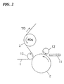
- Fig. 1 shows a prepreg manufacturing apparatus according to a first embodiment of the present invention.
- a reinforcing substrate 1 having a long sheet-shape travels along a traveling direction (TD).
- the reinforcing substrate 1 is made by elongating a fibrous material such as glass cloth.
- a back-up roller 13, a supporting roller 14 and a first transport roller 50 are arranged such that the reinforcing substrate 1 travels straight.
- the traveling direction (TD) of the reinforcing substrate 1 is changed at the back-up roller 13.
- the angle ⁇ 1 between a traveling direction of the reinforcing substrate 1 approaching the back-up roller 13 and a traveling direction of the reinforcing substrate 1 going away from the back-up roller 13 is less than 90°, preferably less than 80°.
- a transferring roller 2 is arranged facing the back-up roller 13.
- the reinforcing substrate 1 travels between the back-up roller 13 and the transferring roller 2.
- the transferring roller 2 is driven in a rotational direction (RD1) opposite to the traveling direction (TD) of the reinforcing substrate 1. Namely, the moving directions of the reinforcing substrate 1 and the transferring roller 2 are opposite at the facing surfaces thereof.
- a metering roller 12 is arranged in the vicinity of the transferring roller 2 and at a downstream of the transferring roller 2 in the traveling direction (TD).
- the metering roller 12 is driven in the same rotational direction (RD2) as that of the transferring roller 2.
- a pressing roller 3 is provided at a downstream of the metering roller 12 and between the back-up roller 13 and the supporting roller 14 along the traveling direction (TD) of the reinforcing substrate 1.
- the pressing roller 3 is driven in a rotational direction (RD3) opposite to the traveling direction (TD) of the reinforcing substrate 1. Namely, the moving directions of the reinforcing substrate 1 and the pressing roller 3 are opposite at the facing surfaces thereof.
- a heating unit 4 is provided between the supporting roller 14 and the first transport roller 50 along the traveling direction (TD). The heating unit 4 is designed to apply heat in a non-contact manner, for example, by a heated air circulating in the heating unit 4.
- thermosetting matrix resin with which the reinforcing substrate 1 is impregnated for example, epoxy resins of the non-solvent type can be used.
- a resin-feeding unit 10 supply the thermosetting matrix resin to the outer circumferential surface of the transferring roller 2.
- the resin-feeding unit 10 includes a first tank (20a) which stores a composition (main agent) having a thermosetting resin as its main component, a second tank (20b) which stores a composition having a curing agent as its main component, and measuring pumps (21a and 21b) which are constituted by gear pumps.
- the measuring pumps (21a and 21b) supply desired amount of the compositions from the tanks (20a and 20b), respectively. Then the measured compositions are mixed.
- thermosetting matrix resin which is a mixture of the respective compositions is fed to the outer circumferential surface the transferring roller 2 in a molten state.
- the thermosetting matrix resin in a molten state fed onto the outer circumferential surface of the transferring roller 2 is spread on the outer circumferential surface of the transferring roller 2 by the metering roller 12 to form a uniform thin film on the outer circumferential surface of the transferring roller 2.
- the reinforcing substrate 1 is pressed on the transferring roller 2 by a back-up roller 13. Accordingly, the uniform film of the thermosetting matrix resin formed on the outer circumferential surface of the transferring roller 2 is transferred to one surface (a first surface (1a)) of the reinforcing substrate 1. As a result, a uniform film of the thermosetting matrix resin is formed on the first surface (1a) of the reinforcing substrate 1. Since the thermosetting matrix resin transferred to the first surface (1a) of the reinforcing substrate 1 is in a molten state, the thermosetting matrix resin naturally permeates the reinforcing substrate 1. In this manner, the thermosetting matrix resin is applied to the reinforcing substrate 1 by the transferring roller 2. Therefore it is not necessary to use a die coater and consequently there is no problem that the thermosetting matrix resin hardens inside the die coater.
- the reinforcing substrate 1 coated with the transferred thermosetting matrix resin in a molten state travels to the pressing roller 3.
- the pressing roller 3 is arranged so as to press the first surface (1a) of the reinforcing substrate 1 on which the thermosetting matrix resin is coated.
- the thermosetting matrix resin on the first surface (1a) of the reinforcing substrate 1 is pressed by the pressing roller 3 so as to permeate thorough the reinforcing substrate 1 to the other surface (a second surface (1b)) of the reinforcing substrate 1.
- thermosetting matrix resin on one surface of the reinforcing substrate 1 by using the transferring roller 2
- the reinforcing substrate 1 is uniformly impregnated with the thermosetting matrix resin. Therefore, it is not necessary to install die coaters on both sides of the reinforcing substrate 1, which are used in the conventional apparatus to apply the thermosetting matrix resin on the both sides of the reinforcing substrate 1.
- thermosetting matrix resin is transferred onto the first surface of the reinforcing substrate 1 by the transferring roller 2 and the thermosetting matrix resin transferred onto the first surface (1a) is pushed into the reinforcing substrate 1 to permeate it by pressing the pressing roller 3 on the same side (the first surface) of the reinforcing substrate 1, air contained inside the reinforcing substrate 1 easily escapes from the second surface of the reinforcing substrate 1 without being entrapped therein. Therefore, the generation of voids in the reinforcing substrate 1 can be prevented.
- the pressing roller 3 In order to control an amount of the thermosetting matrix resin which permeates through the reinforcing substrate 1 to the second surface (1b), the pressing roller 3 is rotated in either direction opposite to or same as the traveling direction (TD) of the reinforcing substrate 1, and otherwise stopped.
- the pressing roller 3 is driven in a rotational direction (RD4) opposite to the traveling direction (TD) of the reinforcing substrate 1.
- the moving directions of the reinforcing substrate 1 and the pressing roller 3 are opposite at the facing surfaces thereof.
- the thermosetting matrix resin in a molten state on the first surface of the reinforcing substrate 1 is pressed into the reinforcing substrate 1 by the pressing roller 3.
- the pressing force of this pressing action becomes stronger as the rotational speed (peripheral velocity) of the pressing roller 3 increases, and consequently the amount of the thermosetting matrix resin which permeates through the reinforcing substrate 1 to the second surface thereof increases. Therefore, by adjusting the rotational speed (peripheral velocity) of the pressing roller 3, the permeation amount of the thermosetting matrix resin is easily controlled.
- the pressing roller 3 is driven in a rotational direction (RD5) same as the traveling direction (TD) of the reinforcing substrate 1. Namely, the moving directions of the reinforcing substrate 1 and the pressing roller 3 are the same at the facing surfaces thereof. In this manner, since opposing faces of the reinforcing substrate 1 and the pressing roller 3 move in the same direction, the thermosetting matrix resin in a molten state on the first surface of the reinforcing substrate 1 is pressed into the reinforcing substrate 1 to permeate it to the second surface thereof by a pressurizing action of the pressing roller 3.
- thermosetting matrix resin which permeates the reinforcing substrate 1 to the second surface (1b) decreases.
- the amount of the thermosetting matrix resin which permeates the reinforcing substrate 1 to the second surface (1b) increases. Therefore, by adjusting the winding angle ⁇ R , the permeation amount of the thermosetting matrix resin is easily controlled.
- thermosetting matrix resin is coated on and permeated the reinforcing substrate in the foregoing process
- the reinforcing substrate 1 moves to the heating unit 4. While the reinforcing substrate 1 passes through the heating unit 4 in a non-contact manner, the thermosetting matrix resin is heated so that the thermosetting matrix resin is semi-cured to be the B stage, and a sheet-shape prepreg 22 is thereby obtained.
- This sheet-shape prepreg 22 is transported by a transport roller 23 and then may be wound up or cut into predetermined lengths. It may be sent to the further optional process.
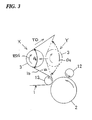
- Fig. 4 shows a prepreg manufacturing apparatus according to a second embodiment of the present invention.
- a heating device 5 is placed between the transferring roller 2 and the pressing roller 3 and on the side of the second surface (1b) of the reinforcing substrate 1.
- a non-contact heating device which uses radiation heat, for example, far infrared rays or the like, or a hot air blow is adopted.
- the other constructions are similar to those as shown in Fig. 1.
- thermosetting matrix resin transferred to the first surface (1a) of the reinforcing substrate 1 from the transferring roller 2 is heated by the heating device 5 so as to keep the temperature of the thermosetting matrix resin to prevent a lowering of the viscosity of the thermosetting matrix resin in the molten state.
- the heating device 5 is preferably adjusted to control the temperature of the thermosetting matrix resin so as to optimize the permeation condition of the thermosetting matrix resin through the reinforcing substrate 1.
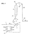
- Fig. 5 shows a prepreg manufacturing apparatus according to a third embodiment of the present invention.
- a plurality of the pressing rollers 3 are provided along the traveling direction (TD) of the reinforcing substrate 1 and between the transferring roller 2 and the heating unit 4.
- the other constructions are similar to those as shown in Fig. 1. Since the thermosetting matrix resin permeates the reinforcing substrate 1 by plural pressing operations performed by the plurality of the pressing rollers 3, the permeation amount of the thermosetting matrix resin can be controlled more precisely. Although the permeation amount of the resin by a single pressing roller 3 is limited, plural pressing rollers 3 can compensate a shortage of the permeation amount. Further, the permeation amount can be more precisely controlled by adjusting respective peripheral velocities of the respective pressing rollers 3.
- Fig. 6 shows a prepreg manufacturing apparatus according to a fourth embodiment of the present invention.
- a back-up sheet 6 is placed at an opposite side of the pressing roller 3 with respect to the reinforcing substrate 1 to contact the second surface (1b) of the reinforcing substrate 1.
- the back-up sheet 6 is an endless belt and made of a material having mold release characteristics with respect to the thermosetting matrix resin, such as a mold-releasing paper.
- the backup sheet 6 is supported around a pair of rollers (26 and 26). The backup sheet 6 moves in the same direction and at the same speed as those of the reinforcing substrate 1 at the contacting surfaces thereof while contacting the reinforcing substrate 1.
- thermosetting matrix resin in a molten state permeates the reinforcing substrate 1 to the second surface by the pressure of the pressing roller 3
- thermosetting matrix resin on the second surface (1b) which has permeated the reinforcing substrate 1 spreads on the second surface (1b) of the reinforcing substrate 1 by the operation of the surface tension of the back-up sheet 6.
- Fig. 7 shows a suction device of a prepreg manufacturing apparatus according to a fifth embodiment of the present invention.
- a suction device 24 is placed facing the pressing roller 3 at an opposite side of the pressing roller 3 with respect to the reinforcing substrate 1.
- the suction device 24 has a suction face (24a) closely facing the second surface (1b) of the reinforcing substrate 1.
- the other constructions are similar to those as shown in Fig. 1.
- a pressure in the space (S) formed between the second surface (1b) of the reinforcing substrate 1 and the suction face (24a) becomes negative.
- thermosetting matrix resin in a molten state which has been transferred onto the first surface (1a) of the reinforcing substrate 1 easily permeates through the reinforcing substrate 1 to the second surface (1b). Therefore, the permeation speed of the thermosetting matrix resin increases and the permeation amount also increases.
- suction action of the suction device 24 to adjust the degree of the negative pressure in the space (S), i.e., the pressure applied to the second surface (1b) of the reinforcing substrate 1, it is possible to control the permeation amount of the thermosetting matrix resin.
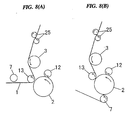
- Figs. 8(A) and 8(B) show a main component of a prepreg manufacturing apparatus according to a sixth embodiment of the present invention.
- a wiping roller 7 is installed on the side of the second surface (1b) and at an upstream position of the buck-up roller 13 along the traveling direction (TD) of the reinforcing substrate 1.
- the wiping roller 7 is movable between a side position of the transferring roller 2 as shown in Fig. 8(A) and a lower position below the transferring roller 2 as shown in Fig. 8(B).
- reference numeral 25 indicates a smoothing roller for smoothing the first and second surfaces (1a and 1b) of the reinforcing substrate 1.
- the wiping roller 7 stays at the side position as shown in Fig. 8(A) and does not contact the reinforcing substrate 1.
- the thermosetting matrix resin fed on the surface of the transferring roller 2 might harden and adhere to the surface of the transferring roller 2, it is necessary to wipe the thermosetting matrix resin on the surface of the transferring roller 2 immediately after the stoppage. Further, when the resin is exchanged to another one, it is also necessary to wipe the thermosetting matrix resin on the surface of the transferring roller 2.
- thermosetting matrix resin when it is necessity to wipe the thermosetting matrix resin on the surface of the transferring roller 2, the wiping roller 7 is moved to the lower position as shown in Fig. 8(B) to wind the reinforcing substrate 1 to the transferring roller 2 and subsequently the wound reinforcing substrate 1 wipes the thermosetting matrix resin on the surface of the transferring roller 2. Therefore, it is possible to prevent the thermosetting matrix resin from adhering to the surface of the transferring roller 2.
- Fig. 9 shows a prepreg manufacturing apparatus according to a seventh embodiment of the present invention.
- reference numeral 8 designates a feed-out unit having a pair of feed-out rollers (28a and 28b) each of which a long reinforcing substrate 1 is wound to.
- the reinforcing substrate 1 fed out from either of the feed-out rollers (28a and 28b) moves to an accumulator unit 9.
- the accumulator unit 9 has a plurality of movable rollers 29 that are movable upward and downward.
- the reinforcing substrate 1 is supported by each movable roller 29 to wind in the accumulator unit 9.
- the operation of the apparatus is continuously carried out by the accumulator unit 9.
- the back-up roller 13, the transferring roller 2, the pressing roller 3, the smoothing roller 25 and the heating unit 4, which are aforementioned in the foregoing embodiments, are placed along the traveling direction (TD) of the reinforcing substrate 1.
- the resin feeding unit 10 is connected to a resin gun 11 from which the molten thermosetting matrix resin is fed to the transferring roller 2.
- the reinforcing substrate 1 impregnated with the thermosetting matrix resin is heated by the heating unit 4 so that the thermosetting matrix resin is semi-cured to the B-stage, and a sheet-shape prepreg 22 is thereby obtained.
- the sheet-shape prepreg 22 is transported by a transport roller 23. After the surface of the prepreg 22 is pressurized and compressed by a compaction roller 30, the sheet-shape prepreg 22 is wound up on a wind-up roller 32 of a wind-up unit 31.
- the sheet-shape prepreg 22 may be cut into a predetermined size by a cutter unit and then the pieces of sheet-shape prepregs 22 may be stacked on the prepreg stacking device.
Landscapes
- Engineering & Computer Science (AREA)
- Mechanical Engineering (AREA)
- Reinforced Plastic Materials (AREA)
- Laminated Bodies (AREA)
Applications Claiming Priority (2)
| Application Number | Priority Date | Filing Date | Title |
|---|---|---|---|
| JP33482298 | 1998-11-25 | ||
| JP33482298 | 1998-11-25 |
Publications (3)
| Publication Number | Publication Date |
|---|---|
| EP1004428A2 true EP1004428A2 (fr) | 2000-05-31 |
| EP1004428A3 EP1004428A3 (fr) | 2001-08-29 |
| EP1004428B1 EP1004428B1 (fr) | 2004-04-28 |
Family
ID=18281614
Family Applications (1)
| Application Number | Title | Priority Date | Filing Date |
|---|---|---|---|
| EP99119714A Expired - Lifetime EP1004428B1 (fr) | 1998-11-25 | 1999-10-05 | Procédé et appareil pour la fabrication de préimpregnés |
Country Status (4)
| Country | Link |
|---|---|
| US (2) | US6245383B1 (fr) |
| EP (1) | EP1004428B1 (fr) |
| DE (1) | DE69916753T2 (fr) |
| TW (1) | TW416907B (fr) |
Families Citing this family (4)
| Publication number | Priority date | Publication date | Assignee | Title |
|---|---|---|---|---|
| DE102010008100A1 (de) * | 2010-02-15 | 2011-08-18 | Fraunhofer-Gesellschaft zur Förderung der angewandten Forschung e.V., 80686 | Verfahren und Vorrichtung zur Imprägnierung von Fasern |
| US10837224B2 (en) * | 2018-01-22 | 2020-11-17 | Ged Integrated Solutions, Inc. | Conveyor and method of manufacture |
| DE102020102015A1 (de) | 2020-01-28 | 2021-07-29 | Comprisetec Gmbh | Herstellung von Prepregs für ein Faserverbundbauteil |
| EP4491363B1 (fr) | 2023-07-13 | 2026-02-18 | Comec - Costruzioni Meccaniche Innovative S.r.l. | Système d'imprégnation automatisé de matériau fibreux dans un format de câble |
Family Cites Families (9)
| Publication number | Priority date | Publication date | Assignee | Title |
|---|---|---|---|---|
| SU1165482A1 (ru) * | 1984-01-12 | 1985-07-07 | Украинский Научно-Исследовательский И Конструкторский Институт По Разработке Машин И Оборудования Для Переработки Пластических Масс,Резины И Искусственной Кожи | Устройство дл пропитки полотна |
| JPS6118661A (ja) * | 1984-07-06 | 1986-01-27 | Nippon Denso Co Ltd | 帯状材料のアキユームレータ |
| JPH07112703B2 (ja) * | 1986-12-17 | 1995-12-06 | 東芝ケミカル株式会社 | プリプレグの製造方法 |
| FI902686A7 (fi) * | 1989-05-29 | 1990-11-30 | Becker Gummiwerke | Menetelmä molemminpuolisesti päällystettyjen hihnakuljettimien valmistamiseksi, erityisesti paperi- ja tekstiilikoneita varten, ja laite menetelmän suorittamiseksi |
| EP0476752B2 (fr) * | 1990-09-17 | 2003-04-02 | Resolution Research Nederland B.V. | Procédé et dispositif pour l'imprégnation avec des résines d'un substrat fibreux |
| MY118735A (en) * | 1993-12-29 | 2005-01-31 | Shell Int Research | Process and apparatus for resin impregnating of a porous web |
| MY131661A (en) * | 1993-12-29 | 2007-08-30 | Faustel Inc | Process and apparatus for resin impregnation of a porous web |
| DE4445478C2 (de) * | 1994-12-20 | 2003-12-18 | Sucker Mueller Hacoba Gmbh | Schlichtvorrichtung |
| EP0810080B1 (fr) * | 1996-05-29 | 2001-07-04 | Matsushita Electric Works, Ltd. | Procédé pour la fabrication de produits préimpregnés utilisables comme matériaux d'isolation électrique |
-
1999
- 1999-09-29 US US09/407,764 patent/US6245383B1/en not_active Expired - Fee Related
- 1999-10-05 EP EP99119714A patent/EP1004428B1/fr not_active Expired - Lifetime
- 1999-10-05 DE DE69916753T patent/DE69916753T2/de not_active Expired - Lifetime
- 1999-10-18 TW TW088118086A patent/TW416907B/zh not_active IP Right Cessation
-
2000
- 2000-10-18 US US09/690,816 patent/US6464783B1/en not_active Expired - Lifetime
Also Published As
| Publication number | Publication date |
|---|---|
| TW416907B (en) | 2001-01-01 |
| DE69916753D1 (de) | 2004-06-03 |
| EP1004428B1 (fr) | 2004-04-28 |
| US6464783B1 (en) | 2002-10-15 |
| DE69916753T2 (de) | 2005-04-21 |
| US6245383B1 (en) | 2001-06-12 |
| EP1004428A3 (fr) | 2001-08-29 |
Similar Documents
| Publication | Publication Date | Title |
|---|---|---|
| EP3702137B1 (fr) | Dispositif de stratification et méthode de stratification | |
| US4329387A (en) | Prepreg material having increased surface tack | |
| EP2436723B1 (fr) | Procédé de fabrication d'un pré-imprimé pour carte de circuit imprimé et dispositif de fabrication d'un pré-imprimé pour carte de circuit imprimé | |
| KR100990417B1 (ko) | 기재의 도포 방법, 기재, 도포 장치, 적층물의 제조 방법및 적층물 | |
| KR101793611B1 (ko) | 다목적 점착테이프 제조장치 | |
| JP4481009B2 (ja) | 多孔質転写表面へ剥離剤を供給して密着転写する方法及び装置 | |
| KR20090051744A (ko) | 도포 방법 및 도포 장치 | |
| JP3336911B2 (ja) | プリプレグの製造方法およびその装置 | |
| JP2001187362A (ja) | 熱硬化性ポリウレタンの連続塗工方法および熱硬化性ポリウレタンシートの製造方法 | |
| JP2003001648A (ja) | ポリウレタンシートの製造方法および製造装置 | |
| EP0324892B2 (fr) | Machine pour coller des films en matière plastique avec dispositifs d'étendage pour matière adhésive | |
| US6245383B1 (en) | Method for manufacturing prepreg in which reinforcing substrate is impregnated with thermosetting matrix resin | |
| CN116981573A (zh) | 用于在带材上涂布油墨薄层的涂布模块 | |
| KR101079772B1 (ko) | 디스플레이 패널용 프리프레그 필름 제조 장치 및 제조 방법 | |
| JP3139359B2 (ja) | 枚葉塗工方法およびカラーフィルタの製造方法 | |
| JP3008814B2 (ja) | プリプレグの製造方法及びその装置 | |
| CN221268716U (zh) | 一种多功能涂布机 | |
| KR102380140B1 (ko) | 코팅 장치 및 이를 이용한 코팅 방법 | |
| KR102265029B1 (ko) | 복합재 라미네이팅 프리프레그 제조장치 | |
| JPH08132537A (ja) | 複合材料の製造方法及びその装置 | |
| CN220742451U (zh) | 转印设备 | |
| US20220410339A1 (en) | Polishing pad with protruded polishing structures, system for manufacturing the same, and method for manufacturing the same | |
| JPH08183029A (ja) | 複合材料の連続的製造方法及びその装置 | |
| KR20070091639A (ko) | 코팅 또는 닥터링 블레이드의 제조방법 | |
| JPH03207472A (ja) | 離型シートへの樹脂コーティング方法 |
Legal Events
| Date | Code | Title | Description |
|---|---|---|---|
| PUAI | Public reference made under article 153(3) epc to a published international application that has entered the european phase |
Free format text: ORIGINAL CODE: 0009012 |
|
| AK | Designated contracting states |
Kind code of ref document: A2 Designated state(s): AT BE CH CY DE DK ES FI FR GB GR IE IT LI LU MC NL PT SE |
|
| AX | Request for extension of the european patent |
Free format text: AL;LT;LV;MK;RO;SI |
|
| PUAL | Search report despatched |
Free format text: ORIGINAL CODE: 0009013 |
|
| AK | Designated contracting states |
Kind code of ref document: A3 Designated state(s): AT BE CH CY DE DK ES FI FR GB GR IE IT LI LU MC NL PT SE |
|
| AX | Request for extension of the european patent |
Free format text: AL;LT;LV;MK;RO;SI |
|
| 17P | Request for examination filed |
Effective date: 20020204 |
|
| AKX | Designation fees paid |
Free format text: DE GB IT |
|
| 17Q | First examination report despatched |
Effective date: 20021028 |
|
| GRAP | Despatch of communication of intention to grant a patent |
Free format text: ORIGINAL CODE: EPIDOSNIGR1 |
|
| GRAS | Grant fee paid |
Free format text: ORIGINAL CODE: EPIDOSNIGR3 |
|
| GRAA | (expected) grant |
Free format text: ORIGINAL CODE: 0009210 |
|
| AK | Designated contracting states |
Kind code of ref document: B1 Designated state(s): DE GB IT |
|
| REG | Reference to a national code |
Ref country code: GB Ref legal event code: FG4D |
|
| REF | Corresponds to: |
Ref document number: 69916753 Country of ref document: DE Date of ref document: 20040603 Kind code of ref document: P |
|
| PLBE | No opposition filed within time limit |
Free format text: ORIGINAL CODE: 0009261 |
|
| STAA | Information on the status of an ep patent application or granted ep patent |
Free format text: STATUS: NO OPPOSITION FILED WITHIN TIME LIMIT |
|
| 26N | No opposition filed |
Effective date: 20050131 |
|
| PGFP | Annual fee paid to national office [announced via postgrant information from national office to epo] |
Ref country code: DE Payment date: 20140930 Year of fee payment: 16 Ref country code: GB Payment date: 20141001 Year of fee payment: 16 |
|
| PGFP | Annual fee paid to national office [announced via postgrant information from national office to epo] |
Ref country code: IT Payment date: 20141015 Year of fee payment: 16 |
|
| REG | Reference to a national code |
Ref country code: DE Ref legal event code: R119 Ref document number: 69916753 Country of ref document: DE |
|
| GBPC | Gb: european patent ceased through non-payment of renewal fee |
Effective date: 20151005 |
|
| PG25 | Lapsed in a contracting state [announced via postgrant information from national office to epo] |
Ref country code: IT Free format text: LAPSE BECAUSE OF NON-PAYMENT OF DUE FEES Effective date: 20151005 Ref country code: GB Free format text: LAPSE BECAUSE OF NON-PAYMENT OF DUE FEES Effective date: 20151005 Ref country code: DE Free format text: LAPSE BECAUSE OF NON-PAYMENT OF DUE FEES Effective date: 20160503 |