EP1004468A2 - Structure d'ouverture de déversement du carburant - Google Patents
Structure d'ouverture de déversement du carburant Download PDFInfo
- Publication number
- EP1004468A2 EP1004468A2 EP99123422A EP99123422A EP1004468A2 EP 1004468 A2 EP1004468 A2 EP 1004468A2 EP 99123422 A EP99123422 A EP 99123422A EP 99123422 A EP99123422 A EP 99123422A EP 1004468 A2 EP1004468 A2 EP 1004468A2
- Authority
- EP
- European Patent Office
- Prior art keywords
- engaging
- screw
- cap
- cylinder
- fuel
- Prior art date
- Legal status (The legal status is an assumption and is not a legal conclusion. Google has not performed a legal analysis and makes no representation as to the accuracy of the status listed.)
- Granted
Links
- 239000000446 fuel Substances 0.000 title claims abstract description 117
- 239000000945 filler Substances 0.000 claims description 42
- 238000007789 sealing Methods 0.000 claims description 11
- 230000000630 rising effect Effects 0.000 claims description 4
- 230000002093 peripheral effect Effects 0.000 claims 11
- 230000007246 mechanism Effects 0.000 description 18
- 230000004048 modification Effects 0.000 description 10
- 238000012986 modification Methods 0.000 description 10
- 230000005489 elastic deformation Effects 0.000 description 9
- 238000013459 approach Methods 0.000 description 3
- 230000006835 compression Effects 0.000 description 2
- 238000007906 compression Methods 0.000 description 2
- 238000007599 discharging Methods 0.000 description 2
- 230000000694 effects Effects 0.000 description 2
- 239000002828 fuel tank Substances 0.000 description 2
- 239000004952 Polyamide Substances 0.000 description 1
- 238000005452 bending Methods 0.000 description 1
- 238000010276 construction Methods 0.000 description 1
- 230000001747 exhibiting effect Effects 0.000 description 1
- 239000003502 gasoline Substances 0.000 description 1
- 238000001746 injection moulding Methods 0.000 description 1
- 229920002647 polyamide Polymers 0.000 description 1
Images


Classifications
-
- B—PERFORMING OPERATIONS; TRANSPORTING
- B60—VEHICLES IN GENERAL
- B60K—ARRANGEMENT OR MOUNTING OF PROPULSION UNITS OR OF TRANSMISSIONS IN VEHICLES; ARRANGEMENT OR MOUNTING OF PLURAL DIVERSE PRIME-MOVERS IN VEHICLES; AUXILIARY DRIVES FOR VEHICLES; INSTRUMENTATION OR DASHBOARDS FOR VEHICLES; ARRANGEMENTS IN CONNECTION WITH COOLING, AIR INTAKE, GAS EXHAUST OR FUEL SUPPLY OF PROPULSION UNITS IN VEHICLES
- B60K15/00—Arrangement in connection with fuel supply of combustion engines or other fuel consuming energy converters, e.g. fuel cells; Mounting or construction of fuel tanks
- B60K15/03—Fuel tanks
- B60K15/04—Tank inlets
- B60K15/0406—Filler caps for fuel tanks
-
- B—PERFORMING OPERATIONS; TRANSPORTING
- B60—VEHICLES IN GENERAL
- B60K—ARRANGEMENT OR MOUNTING OF PROPULSION UNITS OR OF TRANSMISSIONS IN VEHICLES; ARRANGEMENT OR MOUNTING OF PLURAL DIVERSE PRIME-MOVERS IN VEHICLES; AUXILIARY DRIVES FOR VEHICLES; INSTRUMENTATION OR DASHBOARDS FOR VEHICLES; ARRANGEMENTS IN CONNECTION WITH COOLING, AIR INTAKE, GAS EXHAUST OR FUEL SUPPLY OF PROPULSION UNITS IN VEHICLES
- B60K15/00—Arrangement in connection with fuel supply of combustion engines or other fuel consuming energy converters, e.g. fuel cells; Mounting or construction of fuel tanks
- B60K15/03—Fuel tanks
- B60K15/04—Tank inlets
-
- Y—GENERAL TAGGING OF NEW TECHNOLOGICAL DEVELOPMENTS; GENERAL TAGGING OF CROSS-SECTIONAL TECHNOLOGIES SPANNING OVER SEVERAL SECTIONS OF THE IPC; TECHNICAL SUBJECTS COVERED BY FORMER USPC CROSS-REFERENCE ART COLLECTIONS [XRACs] AND DIGESTS
- Y10—TECHNICAL SUBJECTS COVERED BY FORMER USPC
- Y10S—TECHNICAL SUBJECTS COVERED BY FORMER USPC CROSS-REFERENCE ART COLLECTIONS [XRACs] AND DIGESTS
- Y10S220/00—Receptacles
- Y10S220/33—Gasoline tank cap
Definitions
- the present invention relates to an engaging structure of a fuel cap and a filler neck pipe for a fuel pouring inlet of automobile.
- a filler neck pipe extending from a fuel tank has an opening toward the fuel pouring inlet of automobile, and the opening is screwed in engagement with the fuel cap.
- a first screw threaded in an outer periphery of the fuel cap and a second screw threaded in an inner periphery of the filler neck pipe are engaged, so that a sealing part of a fuel cap is fast to the opening of the filler neck pipe so as to close the opening of the filler neck pipe and prevent a fuel steam from volatilization.
- the filler cap is, when pouring the fuel, taken off from the filler neck pipe by rotating the fuel cap, e.g., in a counterclockwise direction, and if, after pouring the fuel, the fuel cap is put on the opening of the filler neck pipe and is rotated, e.g., in a clockwise direction, the opening of the filler neck pipe is closed.
- the fastening should go on until the sealing portion of the fuel cap is fast to the opening of the filler neck pipe and is exactly sealed.
- Fuel caps housing therein torque detecting mechanism and sound mechanism have recently been known.
- the torque detecting mechanism works to cause the fuel cap to run idle and cause the sound mechanism to issue a sound to notify with a sound that the fuel cap is tightened up to the necessary tightening amount.
- An operator can recognize thereby that the fuel cap is exactly tightened, and a dullness or loosening of the sealing portion by over-tightening can be prevented.
- the invention is to solve such an exclusive event, and it is an object of the invention that one step or a plurality of steps are introduced before releasing the engagement between the first screw part of the fuel cap and the second screw part of the opening part of the filler neck pipe, so that, though the engaging distance of the first screw part and the second screw part is shortened, slowly discharging time of the fuel steam may be lengthened, thereby to securely avoid abruptly spouting of the fuel steam or rapidly opening of the fuel cap.
- the structure of the fuel pouring inlet according to the first aspect of the invention is achieved by furnishing a first engaging part having elasticity and elastically deforming in circumferential direction or diameter direction in one sides of an outer periphery of the cylinder part and an inner periphery of the opening, and a second engaging part engageable with the first engaging part in another sides of the outer periphery of the cylinder part and the inner periphery of the opening.
- the first engaging part When mounting the cap, the first engaging part is engaged with the second engaging part and is elastically deformed, and after releasing the engagement of the first engaging part and the second engaging part, the first screw part and the second screw part is screwed whereby the cap is fitted and secured on the filler neck pipe.
- the first engaging part is engaged with the second engaging part and is elastically deformed, and after releasing the engagement of the first engaging part and the second engaging part, the engagement between the cap and the filler neck pipe is released.
- the first engaging part can be constituted by an arm part having elasticity defined in the outer periphery of the cylinder part
- the second engaging part can be constituted by a projection defined in the inner periphery of the opening part
- the first engaging part can be substantially V-shaped, projecting from the outer periphery of the cylinder part and elastically deformable, following the outer periphery, in directions that one end of the first engaging part is near to and remote from another end, and the second engaging part can be constituted by a notch for allowing the engaging part defined in the second screw part to pass under a condition of being elastically deformed.
- the cylinder part when attaching the cap onto the filler neck pipe, at first the cylinder part is inserted in the opening part, and a screw starting end part of the first screw part is engaged with a screw end part of the second screw part.
- the first engaging part and the second engaging part are formed respectively from the screw starting end to a screw terminal end, by rotating the cap, e.g., clockwise, the cylinder part advances in the opening part by the screwing of the first screw part and the second screw part.
- the structure is designed such that the screwing is accomplished at a time when the engagement between the first engaging part and the second engagement is released, the elasticity of the first engaging part can be functioned as a conventional torque detecting mechanism does. But in this case, if the sealing part of the cap is dull or deteriorated, the sealing property of the filler neck pipe is often lowered by the cap. Therefore, it is preferable that the structure is designed such that the screwing is ended after further screwing than the time when the engagement between the first engaging part and the second engaging part is released. In a latter case, it is desirous that the same torque detecting mechanism and the sound mechanism as the related art are provided so as to prevent the sealing portion from being made dull by over tightening
- the cap When the cap is removed from the filler neck pipe for supplying an oil, if rotating the cap, e.g., counterclockwise, the cylinder part is retreated to the opening side in the opening part by the screwing between the first screw part and the second screw part. The sealing property of the sealing part is released thereby, so that the fuel seam is gradually discharged. By more loosening the cap, the first engaging part and the second engaging part are engaged.
- the pressure of the fuel steam in the filler neck pipe acts on the pipe in a direction discharging from the opening part.
- the structure is composed such that the elastic force of the first engaging part acts in the circumferential direction or the diameter direction of the cylinder part. Therefore, even if the pressure of the fuel steam in the filler neck pipe is high, the engagement between the first engaging part and the second engaging part is not released by such pressure, rather the cap is prevented from rapidly opening by the engagement between the first engaging part and the second engaging part.
- the cap is prevented from rapidly opening by the engagement between the first engaging part and the second engaging part. Also under a condition that the first engaging part and the second engaging part are engaged, the fuel steam can be easily discharged from the opening part. If the engaging distance between the first screw part and the second screw part is shortened, a time that the fuel steam is slowly released from the opening part can be shortened and such disadvantage can be avoided that the fuel steam is spouted on taking off the cap.
- the fuel steam can be easily discharged, so that the time that the fuel steam is slowly released from the opening part can be lengthened, and the disadvantage that the fuel steam is spouted on taking off the cap can be avoided.
- the cap when removing the cap, the cap is rotated until the engaging part is engaged with the notch, and is further rotated so that the engaging part is elastically deformed to allow the notch to pass, and the cap is pulled thereafter. Namely, two step actions of rotation and pull are necessary, so that the time that the fuel stem is released in the atmospheric air can be more lengthened, and the disadvantage that the fuel steam is spouted on taking off the cap can be avoided.
- the first engaging part is a convex part elastically deformable as rising and setting in a diameter direction from the outer periphery of the cylinder part
- the second engaging part is composed of the second screw in itself
- the convex part passes the second screw part under a condition that it is set from the cylinder part
- the first screw part is composed which is engageable with the second screw part under a condition that the convex part projects from the cylinder part.
- the convex part When the cap is attached onto the filler neck pipe, at first the cylinder is inserted into the opening part, and then the convex part is pressed by the second screw part and elastically deformed as it is set in the cylinder part, so that the convex gets over the second screw part, and at the same time it is elastically deformed due to reaction force and projected from the cylinder.
- the convex functions as the first screw part and screws the second engaging part.
- the cap For removing the cap, when the cap is rotated, it is retreated in the opening direction of the filler neck pipe by screwing the convex part and the second screw part, and finally when the cap is pulled in the direction remote from the opening part, the convex part is elastically deformed and is released from the engagement with the second screw part, and the cap can be removed.
- the engagement between the convex part and the second screw part prevents the cap from rapidly opening part.
- the fuel steam can be easily discharged, so that the time that the fuel steam is slowly released from the opening part can be lengthened, and the disadvantage that the fuel steam is spouted on taking off the cap can be avoided.
- the engagement between the first engaging part and the second engaging part prevents the cap from rapidly opening part, and the time that the fuel steam is slowly released from the opening part can be lengthened. Therefore, the engaging distance between the first screw part and the second screw part is shorter than a convention one, for example, being within 360 degree is desirable. Thereby, while keeping safety, the rotation of the cap can be made easy.
- the arm part is formed to extend from the screw starting end of the first screw part and the projection is placed corresponding to a position of the arm part at such a time.
- the resistance is recognized thereby immediately before finishing the screwing, so that the operating feeling is heightened.
- the arm part is easily formed.
- a slant continuing to the projection is preferably formed. In such a way, the resistance may be gradually increased when engaging the arm part and the projection, and the operating feeling is naturally sensed.
- the elastically deforming direction of the arm part may be selected from the circumferential or radius directions of the cylinder part. Depending upon situations, the elastic deformation may be provided in both of the circumferential and radius directions.
- the engaging part is formed to be a substantially V-shaped engaging part, it is preferable that the engaging part is formed in the vicinity of the screw starting end of the first screw part, and the notch is provided between the screw starting and finishing ends of the second screw part. The resistance is recognized thereby immediately before finishing the screwing, so that the operating feeling is heightened.
- the elastic force of the engaging part can be functioned as the related art torque detecting mechanism.
- the second screw part is to be a double-screw thread
- the cylinder part is preferably formed with a positioning projection for engaging the end of the double-screw thread.
- the positioning projection is engaged with the end of the second screw part, so that the structure is composed as the convex part is held at a position engaging the screw starting end of the second screw part, and a positioning performance at attaching the cap is improved.
- the positioning projection is, at pulling, engaged with the end part of the second screw part, a drawing timing may be perceived.
- the convex part may be directly elastically deformable in itself, or may be made indirectly elastically deformable by providing a biasing member to effect the convex part in a projecting direction from the cylinder.
- Fig.1A shows a cross sectional view of the structure of the fuel pouring inlet according to a first embodiment of the present invention.
- Fig.1C shows a perspective view showing a state where a cap 1 is removed from a filler neck pipe 2. This structure of the fuel pouring inlet is applied to a structure of a fuel pouring inlet for a gasoline tank of automobile.
- the first screw part 12 of a single screw thread projects outside in a radius direction, and a distance between a screw starting end part 12a of the first screw part 12 and a screw terminal end part 12b falls in a range of around 360 degree of the outer circumference of the cylinder part 11.
- an arm part 14 extending to a front end side of the cylinder 11 and bending around 30 degree is formed turnably following the outer circumferential surface of the cylinder part 11.
- a filler neck pipe 2 has a metal-made cylindrical opening part 20 at the front end, and when the gasket 17 is attached under pressure to the circumference at the front end of the opening part 20, the opening 29 is air-tightly closed by the cap 1. Further, at the outer circumferential surface of the opening part 20, a lid 21 is turnably held and is biased by a spring 22 to close a rear end opening of the opening part 20.
- the opening part 20 is formed with three vent holes 23.
- the cylinder part 11 is at first inserted in the opening part 20.
- a notch is formed in the second screw part 24 as shown in Fig.1B, and the horizontal distance (a) of the notch is slightly larger than the horizontal length (b) of the arm part 14. Accordingly, the arm part 14 passes through the notch of the second screw part 24, and the first screw part 12 contacts the second screw part 24. Then, the cap 1 is turned clockwise so the first screw part 12 engages the second screw part 24, and the screwing starts.
- the cover part 10 When taking off the cap 1 from the filler neck pipe 2, the cover part 10 is rotated counterclockwise, and the cylinder part 11 is also rotated in synchronization. The moment of rotation, compression of the gasket 17 is released, the fuel steam slowly discharged in the atmospheric air from a space formed between the cap 1 and the filler neck pipe 2.
- the front end of the arm part 14 contacts the projection 26, and while the arm part 14 is gradually elastically deforming in an upper right direction of Fig.1, it gets to the position of the projection 25. Accordingly, the resistance by the elastic force of the arm part 14 gradually increases, and also in this duration the fuel steam is released in the atmospheric air.
- the structure of the fuel pouring inlet of the present embodiment due to the resistance effected by the elastic deformation of the arm part 14, it is difficult to rapidly rotate the cap 1, and a time while the arm part 14 is caused to be elastically deformed is inevitably lengthened. Since the fuel steam is discharged bit by bit in the air in this duration and the pressure of the fuel steam is lowered, at a time when the front end of the arm part 14 gets over the projection 25, the pressure of the fuel steam is almost an atmospheric pressure. Accordingly, it is possible to shorten the screw distance from the time when the front end of the arm part 14 gets over the projection 25 at removing the cap 1, exhibiting the operational excellency. Even if the engagement between the first screw part 12 and the second screw part 24 is released, there is no disadvantage that the fuel steam is spouted at once.
- the resistance by the elastic deformation of the arm part 14 is, when tightening the cap 1, heightened only the moment when the front end of the arm part 14 gets over the projection 25.
- the resistance is slowly heightened immediately after rotating it counterclockwise, and the resistance suddenly fades away when the front end of the arm 14 gets over the projection 25, and thereafter no resistance is perceived. Therefore, the structure is excellent in the operating feeling.
- a structure of a fuel pouring inlet shown in Fig.4 is that the arm part 14 is elastically deformable in the circumferential direction of the cylinder 11 and is defined with a concave part 15 (a bore being allowed) for allowing deformation of the arm part 14.
- the arm part 14 extends almost in an axial direction of the cylinder part 11, extending from the upper part of the cylinder part 11 across the first screw part 12.
- This arm part 14 is elastically deformable in the radius direction of the cylinder part 11, and is defined with a bore 15 for allowing deformation of the arm part 14.
- a protrusion 14a being projected in the radius direction of the cylinder part 11 is formed at the tip end of the arm part 14. The protrusion 14a contacts the projection 25.
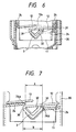
- Fig.6 illustrates the structure of the fuel pouring inlet according to a second embodiment of the present invention.
- This structure of the fuel pouring inlet is the same as the first embodiment excepting different structure to be described in the following.
- the opening part 20 has the second screw part 24 of a double screw thread, and between the screw starting end 24a of the second screw part 24 and the screw terminal end 24b, as shown in Figs.7 and 8, a notch of a horizontal distance (a) is formed.
- the engaging part 3 is substantially V-shaped, and is allowed for elastic deformation following the outer circumferential surface of the cylinder part 11 by the concave part 32 formed in the periphery.
- a horizontal distance (b) between the end 30 and the other end 31 is slightly larger than the horizontal distance (a) of the notch under a condition where no force is effected on the engaging part 3.
- the cylinder part 11 is at first inserted in the opening part 20 and the cap 1 is turned clockwise. Then, the front end of the engaging part 3 engages the notch of the horizontal distance (a) formed between the screw starting end 24a of the second screw part 24 and the screw terminal end 24b, and under this condition, the cap 1 is pressed in the axial direction. Thereby, the engaging part 3 is pressed by the notch to cause the elastic deformation as shown in Fig.8, and if further pressing, a condition shown in Fig.7 is generated.
- the first screw part 12 engages the second screw part 24 so as to start the screwing.
- the screwing is finished.
- the torque detecting mechanism 16 is worked, and the cylinder part 11 is not rotated but the cover part 10 only is rotated clockwise.
- the sound mechanism (not shown) issues a voice, and the operator recognizes it, thereby enabling to prevent the gasket 17 from being made dull.
- the cover part 10 When taking off the cap 1 from the filler neck pipe 2, the cover part 10 is rotated counterclockwise, and the cylinder part 11 is also rotated in synchronization. The moment of rotation, compression of the gasket 17 is released, the fuel steam is slowly discharged in the atmospheric air from the space formed between the cap 1 and the filler neck pipe 2.
- the fuel steam slowly goes out in the atmospheric air from the space between the cap 1 and the opening part 20. Accordingly, the time that the steam slowly goes out in the atmospheric air is longer, and there is no disadvantage that the fuel steam is spouted at once.
- the examples of the double screw thread are shown in the first screw part 12 and the second screw part 24 (simplified in Figs.7 and 8), and of course the same working and effect can be brought about in the single screw thread.
- Fig.9 shows a modification of the second embodiment.
- the end 30 and the other end 31 of the engaging part 3 are independent and composed elastically deformably.
- the cap 1 when the cap 1 is tightened, it is pressed by the screw starting end 24a of the first screw part 24 and the screw terminal end 24b, so that the engaging part 3 is elastically deformed in a direction that the end 30 and the other end 31 approach each other, and the engaging part 3 is pressed into the notch and the screwing starts.
- the other end 31 When removing the cap 1, the other end 31 is pressed by the screw terminal end 24b and is elastically deformed, and if further pulling the cap 1, the engaging part 3 is elastically deformed in the direction that one end 30 and the other end 31 more approach, and the cap 1 can be pulled out at a time that the horizontal distance (b) of one end 30 and the other end 31 is smaller than the horizontal distance (a) of the notch. Since the number of steps for pulling the cap 1 is increased in comparison with the embodiment in Figs. 6 to 8, the time that the fuel steam goes out into the atmospheric air is more lengthened, and there is no disadvantage that the fuel steam is spouted at once.
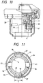
- Fig.10 shows the structure of the fuel pouring inlet according to a third embodiment.
- This structure of the fuel pouring inlet is the same as the first embodiment excepting different structure to be described in the following.
- an independent engaging ring 4 is coaxially disposed in the inner periphery of the cylinder 11, an independent engaging ring 4 is coaxially disposed.
- the engaging ring 4, as shown in Fig.11, comprises an elastically deformable ring shaped spring part 40 and a pair of convex parts 41 in opposition by 180 degree projecting in the outer circumferential direction. Front ends of the convex parts 41 are curved, projecting outward in the diameter direction from windows 18 formed in the cylinder part 11 and are engageable with the second screw part 24.
- the convex parts 41 are set in the winders 18 so as not to interfere with the second screw part 24.
- a pair of positioning projections 19 are formed extending toward the front end of the cylinder part 11 at positions off by 90 degree from the windows 18, and are composed such that they engage the notches 27 of the horizontal distance (c) formed in the second screw part 24 of the double screw thread.
- the cap 1 is more pressed. Then, the convex part 41 contacting the second screw part 24 receives reaction of pressure from the second screw part 24 and is pressed inward in the diameter direction, and the spring part 40 is elastically deformed in the diameter shrinking direction, whereby the convex parts 41 are set in the windows 18. Thereby the cap 1 can be advanced further inside, and the convex parts 41 get over the second screw part 24.
- the convex parts 41 project in the diameter direction and engage the second screw part 24, and if rotating the cap 1, the convex parts 41 serve as the first screw part 12 and screw in mesh with the second screw part 24. Thereafter, rotating it 45 degree, the torque detecting mechanism is worked to accomplish the tightening.
- the number of steps for pulling the cap 1 is more increased, and the time that the fuel steam goes out into the atmospheric air is more lengthened, and there is no disadvantage tat the fuel steam is spouted at once.
Landscapes
- Engineering & Computer Science (AREA)
- Life Sciences & Earth Sciences (AREA)
- Sustainable Development (AREA)
- Sustainable Energy (AREA)
- Chemical & Material Sciences (AREA)
- Combustion & Propulsion (AREA)
- Transportation (AREA)
- Mechanical Engineering (AREA)
- Cooling, Air Intake And Gas Exhaust, And Fuel Tank Arrangements In Propulsion Units (AREA)
- Closures For Containers (AREA)
Applications Claiming Priority (2)
| Application Number | Priority Date | Filing Date | Title |
|---|---|---|---|
| JP33316098 | 1998-11-24 | ||
| JP33316098 | 1998-11-24 |
Publications (3)
| Publication Number | Publication Date |
|---|---|
| EP1004468A2 true EP1004468A2 (fr) | 2000-05-31 |
| EP1004468A3 EP1004468A3 (fr) | 2001-04-25 |
| EP1004468B1 EP1004468B1 (fr) | 2003-04-09 |
Family
ID=18262969
Family Applications (1)
| Application Number | Title | Priority Date | Filing Date |
|---|---|---|---|
| EP99123422A Expired - Lifetime EP1004468B1 (fr) | 1998-11-24 | 1999-11-24 | Structure d'ouverture de déversement du carburant |
Country Status (3)
| Country | Link |
|---|---|
| US (1) | US6202882B1 (fr) |
| EP (1) | EP1004468B1 (fr) |
| DE (1) | DE69906664T2 (fr) |
Cited By (4)
| Publication number | Priority date | Publication date | Assignee | Title |
|---|---|---|---|---|
| EP1162099A3 (fr) * | 2000-06-07 | 2003-01-02 | Toyoda Gosei Co., Ltd. | Bouchon de réservoir et appareil de bouchon de réservoir |
| EP1145890A3 (fr) * | 2000-04-12 | 2003-03-05 | BLAU Kunststofftechnik Zweigniederlassung der Tesma Europa GmbH | Dispositif de remplissage |
| EP1512572A3 (fr) * | 2003-09-05 | 2007-09-26 | Toyoda Gosei Co., Ltd. | Bouchon de réservoir |
| CN110154740A (zh) * | 2019-06-03 | 2019-08-23 | 戴胜汽车科技(苏州)有限公司 | 一种单响加油口盖 |
Families Citing this family (4)
| Publication number | Priority date | Publication date | Assignee | Title |
|---|---|---|---|---|
| US6648016B2 (en) | 2002-01-24 | 2003-11-18 | Alfmeier Corporation | Valve assembly for a fuel tank |
| US8123058B2 (en) * | 2008-09-11 | 2012-02-28 | Rexam Healthcare Packaging Inc. | Closure with stopping mechanism |
| JP5907028B2 (ja) * | 2012-09-28 | 2016-04-20 | 豊田合成株式会社 | 燃料タンクの開閉装置 |
| US9416698B2 (en) * | 2014-05-13 | 2016-08-16 | Honda Motor Co., Ltd. | Fastening method, assembly and structure of engine oil fill extension tube |
Citations (1)
| Publication number | Priority date | Publication date | Assignee | Title |
|---|---|---|---|---|
| JPH10333160A (ja) | 1996-11-28 | 1998-12-18 | Lopco:Kk | 紫外光硬化型樹脂用の紫外光照射装置および紫外光照射方法と紫外光照射装置を備えた基板貼り合わせ処理システム |
Family Cites Families (8)
| Publication number | Priority date | Publication date | Assignee | Title |
|---|---|---|---|---|
| US4020970A (en) * | 1975-12-24 | 1977-05-03 | Illinois Tool Works Inc. | Rotatable closure device |
| US4497419A (en) * | 1984-02-02 | 1985-02-05 | Stant Inc. | One-piece cap |
| JP3118879B2 (ja) * | 1991-06-27 | 2000-12-18 | 豊田合成株式会社 | 燃料キャップ |
| GB9406499D0 (en) * | 1994-03-31 | 1994-05-25 | Britax Wingard Ltd | Fuel tank filler pipe closure |
| US5529201A (en) * | 1994-05-20 | 1996-06-25 | Stant Manufacturing Inc. | Cam-on filler neck cap |
| US5524786A (en) * | 1994-12-27 | 1996-06-11 | Ford Motor Company | Body conforming fuel tank cap latch mechanism |
| US5732841A (en) * | 1996-03-19 | 1998-03-31 | Tesma International Inc. | Fuel cap |
| EP1070009B1 (fr) * | 1997-01-16 | 2007-08-29 | Stant Manufacturing Inc. | Bouchon de goulot de remplissage a fermeture rapide |
-
1999
- 1999-11-24 DE DE69906664T patent/DE69906664T2/de not_active Expired - Fee Related
- 1999-11-24 EP EP99123422A patent/EP1004468B1/fr not_active Expired - Lifetime
- 1999-11-24 US US09/444,722 patent/US6202882B1/en not_active Expired - Fee Related
Patent Citations (1)
| Publication number | Priority date | Publication date | Assignee | Title |
|---|---|---|---|---|
| JPH10333160A (ja) | 1996-11-28 | 1998-12-18 | Lopco:Kk | 紫外光硬化型樹脂用の紫外光照射装置および紫外光照射方法と紫外光照射装置を備えた基板貼り合わせ処理システム |
Cited By (9)
| Publication number | Priority date | Publication date | Assignee | Title |
|---|---|---|---|---|
| EP1145890A3 (fr) * | 2000-04-12 | 2003-03-05 | BLAU Kunststofftechnik Zweigniederlassung der Tesma Europa GmbH | Dispositif de remplissage |
| US6905040B2 (en) | 2000-04-12 | 2005-06-14 | Blau Kunststofftechnik Zweigniederlassung Der Tesma Europa Gmbh | Filler device and closure cap having complementary engagement elements |
| EP1162099A3 (fr) * | 2000-06-07 | 2003-01-02 | Toyoda Gosei Co., Ltd. | Bouchon de réservoir et appareil de bouchon de réservoir |
| US6568553B2 (en) | 2000-06-07 | 2003-05-27 | Toyoda Gosei Co., Ltd. | Tank cap and tank cap apparatus |
| EP1415846A3 (fr) * | 2000-06-07 | 2004-12-15 | Toyoda Gosei Co., Ltd. | Bouchon de réservoir et appareil de bouchon de réservoir |
| US6913162B2 (en) | 2000-06-07 | 2005-07-05 | Toyoda Gosei Co., Ltd. | Tank cap and tank cap apparatus |
| EP1512572A3 (fr) * | 2003-09-05 | 2007-09-26 | Toyoda Gosei Co., Ltd. | Bouchon de réservoir |
| CN110154740A (zh) * | 2019-06-03 | 2019-08-23 | 戴胜汽车科技(苏州)有限公司 | 一种单响加油口盖 |
| CN110154740B (zh) * | 2019-06-03 | 2024-01-16 | 戴胜汽车科技(苏州)有限公司 | 一种单响加油口盖 |
Also Published As
| Publication number | Publication date |
|---|---|
| US6202882B1 (en) | 2001-03-20 |
| DE69906664D1 (de) | 2003-05-15 |
| EP1004468B1 (fr) | 2003-04-09 |
| EP1004468A3 (fr) | 2001-04-25 |
| DE69906664T2 (de) | 2004-04-08 |
Similar Documents
| Publication | Publication Date | Title |
|---|---|---|
| US6202882B1 (en) | Structure of fuel pouring inlet | |
| JP2009037843A (ja) | コネクタ | |
| JP2006056454A (ja) | 車両用燃料キャップ | |
| US5582435A (en) | Resin pipe provided with retainer fitting | |
| JP2914195B2 (ja) | 内燃機関のプラグキャップ | |
| EP1512572B1 (fr) | Bouchon de réservoir | |
| JP4130350B2 (ja) | プラグキャップ及びその製造方法 | |
| JP4469235B2 (ja) | 燃料キャップ | |
| JP5125914B2 (ja) | ガスケットとキャップおよびタンク用開閉装置 | |
| JP4877167B2 (ja) | キャップとこれを有する燃料給油装置 | |
| JP3656795B2 (ja) | 筒体と止め具の固定構造 | |
| US20050121454A1 (en) | Fuel cap | |
| US20040262312A1 (en) | Fuel cap device | |
| JP2000219260A (ja) | 燃料注入口構造 | |
| JP2009083547A (ja) | 車両のケーブルガイド | |
| US20050098562A1 (en) | Fuel cap with seal-retention gasket and means | |
| JP2001146245A (ja) | 注出口とキャップとの組合体 | |
| JP4235096B2 (ja) | ヒンジキャップ | |
| JP4179124B2 (ja) | キャップ装置 | |
| JPH11301290A (ja) | 燃料タンク用キャップ | |
| JP2000085826A (ja) | キャップ | |
| JP4780072B2 (ja) | 環状のガスケットとこれを有するキャップ | |
| JPH0751388Y2 (ja) | 自動車用燃料タンク給油口 | |
| JP2513886Y2 (ja) | 車両用フュ―エルフィラ―キャップ | |
| JP4409675B2 (ja) | 筆記具のキャップ装着構造 |
Legal Events
| Date | Code | Title | Description |
|---|---|---|---|
| PUAI | Public reference made under article 153(3) epc to a published international application that has entered the european phase |
Free format text: ORIGINAL CODE: 0009012 |
|
| 17P | Request for examination filed |
Effective date: 19991124 |
|
| AK | Designated contracting states |
Kind code of ref document: A2 Designated state(s): DE FR GB |
|
| AX | Request for extension of the european patent |
Free format text: AL;LT;LV;MK;RO;SI |
|
| PUAL | Search report despatched |
Free format text: ORIGINAL CODE: 0009013 |
|
| AK | Designated contracting states |
Kind code of ref document: A3 Designated state(s): AT BE CH CY DE DK ES FI FR GB GR IE IT LI LU MC NL PT SE |
|
| AX | Request for extension of the european patent |
Free format text: AL;LT;LV;MK;RO;SI |
|
| AKX | Designation fees paid |
Free format text: DE FR GB |
|
| GRAH | Despatch of communication of intention to grant a patent |
Free format text: ORIGINAL CODE: EPIDOS IGRA |
|
| GRAH | Despatch of communication of intention to grant a patent |
Free format text: ORIGINAL CODE: EPIDOS IGRA |
|
| GRAA | (expected) grant |
Free format text: ORIGINAL CODE: 0009210 |
|
| AK | Designated contracting states |
Designated state(s): DE FR GB |
|
| REG | Reference to a national code |
Ref country code: GB Ref legal event code: FG4D |
|
| ET | Fr: translation filed | ||
| PLBE | No opposition filed within time limit |
Free format text: ORIGINAL CODE: 0009261 |
|
| STAA | Information on the status of an ep patent application or granted ep patent |
Free format text: STATUS: NO OPPOSITION FILED WITHIN TIME LIMIT |
|
| 26N | No opposition filed |
Effective date: 20040112 |
|
| PGFP | Annual fee paid to national office [announced via postgrant information from national office to epo] |
Ref country code: FR Payment date: 20041109 Year of fee payment: 6 |
|
| PGFP | Annual fee paid to national office [announced via postgrant information from national office to epo] |
Ref country code: DE Payment date: 20041118 Year of fee payment: 6 |
|
| PGFP | Annual fee paid to national office [announced via postgrant information from national office to epo] |
Ref country code: GB Payment date: 20041124 Year of fee payment: 6 |
|
| PG25 | Lapsed in a contracting state [announced via postgrant information from national office to epo] |
Ref country code: GB Free format text: LAPSE BECAUSE OF NON-PAYMENT OF DUE FEES Effective date: 20051124 |
|
| PG25 | Lapsed in a contracting state [announced via postgrant information from national office to epo] |
Ref country code: DE Free format text: LAPSE BECAUSE OF NON-PAYMENT OF DUE FEES Effective date: 20060601 |
|
| GBPC | Gb: european patent ceased through non-payment of renewal fee |
Effective date: 20051124 |
|
| PG25 | Lapsed in a contracting state [announced via postgrant information from national office to epo] |
Ref country code: FR Free format text: LAPSE BECAUSE OF NON-PAYMENT OF DUE FEES Effective date: 20060731 |
|
| REG | Reference to a national code |
Ref country code: FR Ref legal event code: ST Effective date: 20060731 |