EP1004479A2 - Schablone und perforierte Halterungsplatte - Google Patents
Schablone und perforierte Halterungsplatte Download PDFInfo
- Publication number
- EP1004479A2 EP1004479A2 EP99309024A EP99309024A EP1004479A2 EP 1004479 A2 EP1004479 A2 EP 1004479A2 EP 99309024 A EP99309024 A EP 99309024A EP 99309024 A EP99309024 A EP 99309024A EP 1004479 A2 EP1004479 A2 EP 1004479A2
- Authority
- EP
- European Patent Office
- Prior art keywords
- panel
- pressing
- pillar
- perforated panel
- feet
- Prior art date
- Legal status (The legal status is an assumption and is not a legal conclusion. Google has not performed a legal analysis and makes no representation as to the accuracy of the status listed.)
- Withdrawn
Links
Images


Classifications
-
- B—PERFORMING OPERATIONS; TRANSPORTING
- B60—VEHICLES IN GENERAL
- B60R—VEHICLES, VEHICLE FITTINGS, OR VEHICLE PARTS, NOT OTHERWISE PROVIDED FOR
- B60R16/00—Electric or fluid circuits specially adapted for vehicles and not otherwise provided for; Arrangement of elements of electric or fluid circuits specially adapted for vehicles and not otherwise provided for
- B60R16/02—Electric or fluid circuits specially adapted for vehicles and not otherwise provided for; Arrangement of elements of electric or fluid circuits specially adapted for vehicles and not otherwise provided for electric constitutive elements
- B60R16/0207—Wire harnesses
-
- Y—GENERAL TAGGING OF NEW TECHNOLOGICAL DEVELOPMENTS; GENERAL TAGGING OF CROSS-SECTIONAL TECHNOLOGIES SPANNING OVER SEVERAL SECTIONS OF THE IPC; TECHNICAL SUBJECTS COVERED BY FORMER USPC CROSS-REFERENCE ART COLLECTIONS [XRACs] AND DIGESTS
- Y10—TECHNICAL SUBJECTS COVERED BY FORMER USPC
- Y10S—TECHNICAL SUBJECTS COVERED BY FORMER USPC CROSS-REFERENCE ART COLLECTIONS [XRACs] AND DIGESTS
- Y10S269/00—Work holders
- Y10S269/90—Supporting structure having work holder receiving apertures or projections
-
- Y—GENERAL TAGGING OF NEW TECHNOLOGICAL DEVELOPMENTS; GENERAL TAGGING OF CROSS-SECTIONAL TECHNOLOGIES SPANNING OVER SEVERAL SECTIONS OF THE IPC; TECHNICAL SUBJECTS COVERED BY FORMER USPC CROSS-REFERENCE ART COLLECTIONS [XRACs] AND DIGESTS
- Y10—TECHNICAL SUBJECTS COVERED BY FORMER USPC
- Y10S—TECHNICAL SUBJECTS COVERED BY FORMER USPC CROSS-REFERENCE ART COLLECTIONS [XRACs] AND DIGESTS
- Y10S269/00—Work holders
- Y10S269/903—Work holder for electrical circuit assemblages or wiring systems
Definitions
- the present invention relates to an assembly jig for wire harnesses to be fastened to a perforated panel on which multiple holes are arranged and formed with a predetermined spacing, and to a perforated panel fixture for fastening the assembly jig.
- a wiring base board is used on which a number of wiring jigs are provided. Conventionally, holes are formed at predetermined positions in the base board and the lower end of the wiring jig is fitted into the holes and fastened with bolts on both top and bottom surfaces of the perforated board.
- the board mounted with the wiring jig becomes the exclusive article for assembling the particular kind of wire harness.
- This general-use type wiring board allows a wiring jig to be mounted from the top surface but the mounting position of the wiring jigs is determined by the mounting hole position that is preliminarily formed.
- the mounting position can be adjusted after mounting the wiring jigs by adopting a mounting hole with an ellipse shape on the perforated panel, fastening with bolts from the top and bottom surfaces of the perforated panel is necessary in this case calling for additional time and labour for mounting the wiring jigs.
- an object of the present invention is to provide a wire harness assembly jig capable of being easily fitted and taken out and which can be arranged at any position from the top surface of the perforated panel and also to provide a perforated panel fixture for supporting this assembly.
- a fixture for fastening a wire harness assembling jig on a perforated panel in which multiple holes are arranged and formed with a predetermined spacing comprising a supporting member for supporting an assembly jig, and a pressing mechanism for securing the supporting member onto the perforated panel, the pressing mechanism including a pressing member having a pair of feet for positioning the pressing mechanism from one side of the panel by being interfit with two mounting holes in close proximity to each other.
- the pair of feet penetrate through each hole in the perforated panel and are provided with protrusions for engaging with the other side of the perforated panel.
- the supporting member has a pillar supporting area interfit with a pillar and a bench board arranged on the perforated panel
- the pressing member has a transverse portion which spans over the bench board and is connected at opposite ends with the pair of feet, and a pressing screw provided on the transverse portion for pressing down the bench board.
- the assembly jig can be mounted at any desired position without restriction to the position of holes pre-formed with predetermined spacing in the perforated panel.
- fitting and removing the assembly jig from the top surface of the perforated panel as well as arranging it onto any position can be implemented from one side of the perforated panel.
- an assembly jig for assembling wire harnesses fastened on a perforated panel in which multiple holes are arranged and formed with a pre-determined spacing comprising predetermined parts for use of assembling, a pillar having a pointed lower end which supports the part from the lower side, a supporting member for supporting the pillar, and a pressing mechanism for pressing and fastening the supporting member onto the perforated panel, the pressing mechanism including a pressing member having a pair of feet for positioning the pressing mechanism from one side of the panel by being interfit with two mounting holes in close proximity to each other.
- a wiring jig is provided with a cable receiving area which receives cables.
- a crank-form supporting member supports a pillar which supports the cable receiving area.
- the supporting member is fastened to a perforated panel by tightening a pressing screw of a pressing member having a pair of feet mounted in adjacent holes of the panel. Loosening the pressing screw allows the supporting member to rotate and also slide so that the pillar can be installed at any desired position without being restricted by the position of the holes that are pre-formed with predetermined spacing in the perforated panel.
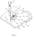
- Figure 1 represents a perspective view showing an embodiment of the invention in which one wiring jig 1 for an assembly jig is mounted on a perforated panel 3.
- the wiring jig 1 is equipped with a cable receiving area 4 supported by a pillar 5 from the lower side.
- This pillar 5 is supported by a crank-form supporting member 6 fastened by a pressing member 7 onto the surface 3a of the perforated panel 3.
- the perforated panel 3 comprises a flat board having a certain thickness and is, for example, constructed from a metallic plate.
- a number of round mounting holes 2 are provided in the board which penetrate through the top surface 3a and bottom surface 3b of the flat board.
- the mounting holes 2 are aligned in two directions at right angles to each other, e.g. vertical and horizontal directions. In each direction, the holes 2 are arranged at predetermined regular intervals of a certain pitch P, but with a different pitch between the vertical and the horizontal directions.
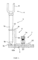
- FIG. 2 of the drawings shows a side view of the wiring jig 1.
- the cable receiving area 4 is equipped with a U-shaped metal support 41 for receiving the cable.
- a cable receiving area 4 is illustrated but the invention is not restricted to the use of a jig for cable receiving alone, i.e. any kind of jig may be applicable so long as it may be a jig necessary for assembling a wire harness, such as a connector receiving jig, a clamp mounting jig, an indicating jig for a taping position and the like.
- the pillar 5 is of a substantially circular outline.
- the lower end 5b of the pillar 5 is of sharply pointed conical form. By mounting the lower end 5 b to fit on the top surface 3a, the pillar 5 can be mounted at any desired position on the perforated panel 3 with fine accuracy.
- the supporting member 6 is of generally Z outline comprising an upper horizontal arm or pillar supporting area 61, a lower horizontal arm or bench board 63 and a vertical connection web or board 64 from opposite each of which the area 61 and the board 63 extend in opposite directions.
- the supporting member 6 is formed from a flat strip of rectangular section.
- the bench board 63 is arranged on the top surface 3a of the perforated panel 3, and is pressed against the perforated panel 3 by the use of a pressing screw 74 of the pressing member 7 as described in more detail later herein.
- connection board 64 is provided for connecting the pillar supporting area 61 and the bench board 63, and extends in a vertical direction from one end 63a of the bench board 63 to one end of the pillar supporting area 61.
- the pillar supporting area 61 extends parallel to the bench board 63.
- a circular hole 62 which receives the above-mentioned pillar 5 is formed on the rear central part of the pillar supporting area 61.
- the pillar supporting area 61 supports the pillar 5 in an area 5c intermediate its ends.
- the supporting member 6 since the supporting member 6 is provided in a crank form, the supporting member 6 can support the intermediate area 5c of the pillar 5 in such a manner that the pillar 5 is stabilised.
- FIG. 3 of the drawings illustrates in detail the structure of the pressing member 7.
- the pressing member 7 is of metal and fastens the supporting member 6 onto the perforated panel 3.
- the pressing member 7 is equipped with a transverse bar or bridge 72 which is connected at opposite ends 72a and 72b to a pair of feet 71 thereby constituting a member of inserted "U" outline.
- each foot 71 protrusions 75 for engaging with the bottom surface 3b of the perforated panel 3 are provided.
- the engaging protrusions 75 extend in the same direction, towards the right as seen in Figure 3.
- the pressing member 7 is mounted on the top surface 3a of the perforated panel 3 by making the feet 71 interfit with two mounting holes 2 which are adjacent to each other from the top surface 3a.
- the member 7 is then displaced in a transverse direction to cause the protrusions 75 to engage with the bottom surface 3b of the perforated panel 3.
- transverse bar 72 spans over the top surface 3a of the bench board 63 of the support member 6.
- the intermediate area 72c of this transverse bar 72 is expanded internally to accommodate a screw hole 73 which extends in an upright direction through the intermediate area 72c.
- the pressing screw 74 is screwed into the screw hole 73 from the upper side. Tightening the pressing screw 74 will cause the bench board 63 to press down on the top surface 3a of the perforated panel with the feet 71 lifting up to engage the bottom surface in order to secure the supporting member 6 on the perforated panel 3.
- the transverse bar 72 is composed of two parts which are laminated together.
- the wiring jig 1 is fastened and the mounting strength of the wiring jig 1 is high enough.
- securing the support member 6 from the top surface 3a only of the perforated panel 3 makes it possible to mount and take out the wiring jig 1 from one side of the perforated panel 3 without requiring access to the other side of the panel 3.
- Figure 4 represents a plan view of the wiring jig 1. As shown, loosening the pressing screw 74 allows the supporting member 6 to rotate in a direction shown with an arrow mark A1 and/or to slide in a direction shown with an arrow mark A2. That is, the position of pillar 5 can be adjusted to any desired position without being restricted by the position of the mounting holes 2 which are pre-formed at a predetermined position in the perforated panel 3.
Landscapes
- Engineering & Computer Science (AREA)
- Mechanical Engineering (AREA)
- Installation Of Indoor Wiring (AREA)
- Supply And Installment Of Electrical Components (AREA)
Applications Claiming Priority (2)
| Application Number | Priority Date | Filing Date | Title |
|---|---|---|---|
| JP33460298A JP3552928B2 (ja) | 1998-11-25 | 1998-11-25 | ワイヤーハーネスの組立用治具 |
| JP33460298 | 1998-11-25 |
Publications (2)
| Publication Number | Publication Date |
|---|---|
| EP1004479A2 true EP1004479A2 (de) | 2000-05-31 |
| EP1004479A3 EP1004479A3 (de) | 2000-07-12 |
Family
ID=18279235
Family Applications (1)
| Application Number | Title | Priority Date | Filing Date |
|---|---|---|---|
| EP99309024A Withdrawn EP1004479A3 (de) | 1998-11-25 | 1999-11-12 | Schablone und perforierte Halterungsplatte |
Country Status (3)
| Country | Link |
|---|---|
| US (1) | US6308944B1 (de) |
| EP (1) | EP1004479A3 (de) |
| JP (1) | JP3552928B2 (de) |
Cited By (2)
| Publication number | Priority date | Publication date | Assignee | Title |
|---|---|---|---|---|
| FR2956828A1 (fr) * | 2010-02-26 | 2011-09-02 | Peugeot Citroen Automobiles Sa | Machine d'assemblage comportant un poste commun d'outillages |
| CN108056861A (zh) * | 2018-01-31 | 2018-05-22 | 重庆安布伦斯科技有限公司 | 用于担架的组装系统 |
Families Citing this family (14)
| Publication number | Priority date | Publication date | Assignee | Title |
|---|---|---|---|---|
| JP3598914B2 (ja) * | 1999-11-24 | 2004-12-08 | 住友電装株式会社 | 多孔板用組立保持具固定装置 |
| DE202005011793U1 (de) * | 2005-07-27 | 2005-10-06 | Haimer Gmbh | Positioniereinrichtung für Span abhebende Werkzeuge in Werkzeugfutteralen |
| US7607870B2 (en) * | 2006-11-02 | 2009-10-27 | Hughes Jr Robert K | Rotary tube notching apparatus |
| DE102007011931A1 (de) * | 2007-03-13 | 2008-09-18 | Krones Ag | Vorrichtung zum Behandeln von Behältnissen |
| US8764000B2 (en) * | 2007-06-28 | 2014-07-01 | United Technologies Corporation | Tool alignment fixture |
| US10256011B2 (en) | 2014-10-31 | 2019-04-09 | Panduit Corp. | Wire harness assembly system |
| US10441993B2 (en) | 2015-09-11 | 2019-10-15 | Lear Corporation | Vertical twisting system and method |
| US9561910B1 (en) | 2016-02-08 | 2017-02-07 | Lear Corporation | Vertical assembly line |
| US10242771B2 (en) | 2016-08-16 | 2019-03-26 | Design Ready Controls, Inc. | Electrical control panel wire harness assembly pegs |
| US10388436B1 (en) | 2016-08-16 | 2019-08-20 | Design Ready Controls, Inc. | Wire harness assembly holding device |
| US10411444B2 (en) | 2016-08-16 | 2019-09-10 | Design Ready Controls, Inc. | Method of assembling electrical control panel wire harness |
| US11232888B1 (en) | 2016-08-16 | 2022-01-25 | Design Ready Controls, Inc. | Method of assembling electrical control panel wire harness |
| CN113632182B (zh) * | 2019-03-29 | 2022-12-30 | 株式会社自动网络技术研究所 | 布线模块 |
| DE102022004406A1 (de) | 2022-11-25 | 2024-01-04 | Mercedes-Benz Group AG | Halteeinrichtung zum Halten einer elektrischen Leitung |
Family Cites Families (14)
| Publication number | Priority date | Publication date | Assignee | Title |
|---|---|---|---|---|
| US287884A (en) * | 1883-11-06 | Thill-coupling jack | ||
| JPH03114111A (ja) * | 1989-09-28 | 1991-05-15 | Yazaki Corp | ワイヤハーネス布線治具 |
| JPH0569823A (ja) | 1990-03-16 | 1993-03-23 | Nippon Sharyo Seizo Kaisha Ltd | 鉄道車両用構体 |
| JPH082887Y2 (ja) * | 1990-05-14 | 1996-01-29 | 住友電装株式会社 | ワイヤーハーネス組立板用案内治具 |
| JPH0562542A (ja) | 1991-08-29 | 1993-03-12 | Fujikura Ltd | ワイヤーハーネス組立治具 |
| JPH05114315A (ja) * | 1991-10-18 | 1993-05-07 | Yazaki Corp | ワイヤーハーネスの配索治具及び配索方法 |
| US5168904A (en) * | 1991-10-23 | 1992-12-08 | Electro-Wire Products, Inc. | Reconfigurable wiring harness jig |
| JP2917750B2 (ja) * | 1993-05-19 | 1999-07-12 | 住友電装株式会社 | ワイヤーハーネス組立板用案内治具 |
| US5490664A (en) * | 1994-01-31 | 1996-02-13 | United Technologies Automotive, Inc. | Universal fork wire harness assembly jig |
| ES1029511Y (es) | 1994-11-23 | 1995-11-01 | Mecanismos Aux Ind | Tablero modular para montaje de cableados perfeccionado. |
| US5630576A (en) * | 1995-08-11 | 1997-05-20 | Williams; Willis R. | Saddle clamp workpiece clamping apparatus |
| JP3114111B2 (ja) | 1995-11-16 | 2000-12-04 | 日本電信電話株式会社 | 論理エミュレーション方法及びシステム |
| US6003852A (en) * | 1997-06-09 | 1999-12-21 | Sumitomo Wiring Systems, Ltd. | Assembly device for a wiring harness |
| EP0889278A1 (de) * | 1997-07-02 | 1999-01-07 | Virax S.A. | Vorrichtung zum Festhalten eines Objektes am Rand einer Fläche, insbesondere ein Werkzeug wie ein Spannstock oder dergleich auf einer Werkbank |
-
1998
- 1998-11-25 JP JP33460298A patent/JP3552928B2/ja not_active Expired - Fee Related
-
1999
- 1999-11-12 EP EP99309024A patent/EP1004479A3/de not_active Withdrawn
- 1999-11-23 US US09/447,575 patent/US6308944B1/en not_active Expired - Fee Related
Non-Patent Citations (1)
| Title |
|---|
| None |
Cited By (3)
| Publication number | Priority date | Publication date | Assignee | Title |
|---|---|---|---|---|
| FR2956828A1 (fr) * | 2010-02-26 | 2011-09-02 | Peugeot Citroen Automobiles Sa | Machine d'assemblage comportant un poste commun d'outillages |
| CN108056861A (zh) * | 2018-01-31 | 2018-05-22 | 重庆安布伦斯科技有限公司 | 用于担架的组装系统 |
| CN108056861B (zh) * | 2018-01-31 | 2019-09-10 | 重庆安布伦斯科技有限公司 | 用于担架的组装系统 |
Also Published As
| Publication number | Publication date |
|---|---|
| JP2000164054A (ja) | 2000-06-16 |
| EP1004479A3 (de) | 2000-07-12 |
| US6308944B1 (en) | 2001-10-30 |
| JP3552928B2 (ja) | 2004-08-11 |
Similar Documents
| Publication | Publication Date | Title |
|---|---|---|
| US6308944B1 (en) | Assembly jig including a fixture for a perforated panel | |
| US5694678A (en) | Universal wire harness retainer clip holding system | |
| US11527875B2 (en) | Mounting bracket assembly for an electrical receptacle system | |
| US4181293A (en) | Handrail support hardware | |
| US20040129826A1 (en) | Simplified interconnect for center of wide body aircraft | |
| JPH0562542A (ja) | ワイヤーハーネス組立治具 | |
| JPH07282654A (ja) | ワイヤーハーネスの組立用支持具 | |
| JP2007131158A (ja) | バッテリ固定装置 | |
| JP4234350B2 (ja) | 机等とローパーティションとの連結構造 | |
| CA3204160A1 (en) | Roof rack for a motor vehicle, motor vehicle, and method for producing a roof rack | |
| KR0185336B1 (ko) | 와이어링 하니스 제작 보오드 | |
| JP3925843B2 (ja) | 機器取付台 | |
| JP4071931B2 (ja) | 部材取付構造 | |
| CN219394725U (zh) | 一种光伏组件的安装装置和光伏组件安装系统 | |
| JP3034466B2 (ja) | 物干竿等の支持装置 | |
| JP3080571B2 (ja) | キャリヤの脚部材 | |
| JP3614022B2 (ja) | 配電ブロックの取付構造 | |
| JPH0610027Y2 (ja) | 雪辷り止め金具 | |
| JPH0679028U (ja) | 布線治具 | |
| KR0140221Y1 (ko) | 차량용 파워 트레인 탑재용 브라켓 구조 | |
| EP1037350A1 (de) | Verbindungsanordnung für einen Kabelkanal | |
| JP2961416B1 (ja) | 省スペース型ブラケット | |
| JP3007845U (ja) | フロアパネルの支持脚 | |
| KR200153571Y1 (ko) | 차량의 리어콘솔 고정구조 | |
| JPH073231U (ja) | 電気接続箱の車体取付け構造 |
Legal Events
| Date | Code | Title | Description |
|---|---|---|---|
| PUAI | Public reference made under article 153(3) epc to a published international application that has entered the european phase |
Free format text: ORIGINAL CODE: 0009012 |
|
| PUAL | Search report despatched |
Free format text: ORIGINAL CODE: 0009013 |
|
| 17P | Request for examination filed |
Effective date: 19991202 |
|
| AK | Designated contracting states |
Kind code of ref document: A2 Designated state(s): DE FR GB |
|
| AX | Request for extension of the european patent |
Free format text: AL;LT;LV;MK;RO;SI |
|
| AK | Designated contracting states |
Kind code of ref document: A3 Designated state(s): AT BE CH CY DE DK ES FI FR GB GR IE IT LI LU MC NL PT SE |
|
| AX | Request for extension of the european patent |
Free format text: AL;LT;LV;MK;RO;SI |
|
| AKX | Designation fees paid |
Free format text: DE FR GB |
|
| STAA | Information on the status of an ep patent application or granted ep patent |
Free format text: STATUS: THE APPLICATION HAS BEEN WITHDRAWN |
|
| 18W | Application withdrawn |
Withdrawal date: 20011217 |