EP1004492B1 - Limitation de course de pédale pour systèmes de freinage électro-hydrauliques - Google Patents
Limitation de course de pédale pour systèmes de freinage électro-hydrauliques Download PDFInfo
- Publication number
- EP1004492B1 EP1004492B1 EP99309338A EP99309338A EP1004492B1 EP 1004492 B1 EP1004492 B1 EP 1004492B1 EP 99309338 A EP99309338 A EP 99309338A EP 99309338 A EP99309338 A EP 99309338A EP 1004492 B1 EP1004492 B1 EP 1004492B1
- Authority
- EP
- European Patent Office
- Prior art keywords
- pressure
- braking
- hydraulic
- brake
- master cylinder
- Prior art date
- Legal status (The legal status is an assumption and is not a legal conclusion. Google has not performed a legal analysis and makes no representation as to the accuracy of the status listed.)
- Expired - Lifetime
Links
- 238000002955 isolation Methods 0.000 claims description 11
- 230000003111 delayed effect Effects 0.000 claims description 2
- 239000012530 fluid Substances 0.000 description 5
- 230000001133 acceleration Effects 0.000 description 3
- 230000000694 effects Effects 0.000 description 2
- 230000003213 activating effect Effects 0.000 description 1
- 230000000994 depressogenic effect Effects 0.000 description 1
- 238000010586 diagram Methods 0.000 description 1
- 238000006073 displacement reaction Methods 0.000 description 1
- 238000004088 simulation Methods 0.000 description 1
Images


Classifications
-
- B—PERFORMING OPERATIONS; TRANSPORTING
- B60—VEHICLES IN GENERAL
- B60T—VEHICLE BRAKE CONTROL SYSTEMS OR PARTS THEREOF; BRAKE CONTROL SYSTEMS OR PARTS THEREOF, IN GENERAL; ARRANGEMENT OF BRAKING ELEMENTS ON VEHICLES IN GENERAL; PORTABLE DEVICES FOR PREVENTING UNWANTED MOVEMENT OF VEHICLES; VEHICLE MODIFICATIONS TO FACILITATE COOLING OF BRAKES
- B60T8/00—Arrangements for adjusting wheel-braking force to meet varying vehicular or ground-surface conditions, e.g. limiting or varying distribution of braking force
- B60T8/32—Arrangements for adjusting wheel-braking force to meet varying vehicular or ground-surface conditions, e.g. limiting or varying distribution of braking force responsive to a speed condition, e.g. acceleration or deceleration
- B60T8/321—Arrangements for adjusting wheel-braking force to meet varying vehicular or ground-surface conditions, e.g. limiting or varying distribution of braking force responsive to a speed condition, e.g. acceleration or deceleration deceleration
-
- B—PERFORMING OPERATIONS; TRANSPORTING
- B60—VEHICLES IN GENERAL
- B60T—VEHICLE BRAKE CONTROL SYSTEMS OR PARTS THEREOF; BRAKE CONTROL SYSTEMS OR PARTS THEREOF, IN GENERAL; ARRANGEMENT OF BRAKING ELEMENTS ON VEHICLES IN GENERAL; PORTABLE DEVICES FOR PREVENTING UNWANTED MOVEMENT OF VEHICLES; VEHICLE MODIFICATIONS TO FACILITATE COOLING OF BRAKES
- B60T13/00—Transmitting braking action from initiating means to ultimate brake actuator with power assistance or drive; Brake systems incorporating such transmitting means, e.g. air-pressure brake systems
- B60T13/10—Transmitting braking action from initiating means to ultimate brake actuator with power assistance or drive; Brake systems incorporating such transmitting means, e.g. air-pressure brake systems with fluid assistance, drive, or release
- B60T13/66—Electrical control in fluid-pressure brake systems
- B60T13/68—Electrical control in fluid-pressure brake systems by electrically-controlled valves
- B60T13/686—Electrical control in fluid-pressure brake systems by electrically-controlled valves in hydraulic systems or parts thereof
-
- B—PERFORMING OPERATIONS; TRANSPORTING
- B60—VEHICLES IN GENERAL
- B60T—VEHICLE BRAKE CONTROL SYSTEMS OR PARTS THEREOF; BRAKE CONTROL SYSTEMS OR PARTS THEREOF, IN GENERAL; ARRANGEMENT OF BRAKING ELEMENTS ON VEHICLES IN GENERAL; PORTABLE DEVICES FOR PREVENTING UNWANTED MOVEMENT OF VEHICLES; VEHICLE MODIFICATIONS TO FACILITATE COOLING OF BRAKES
- B60T8/00—Arrangements for adjusting wheel-braking force to meet varying vehicular or ground-surface conditions, e.g. limiting or varying distribution of braking force
- B60T8/32—Arrangements for adjusting wheel-braking force to meet varying vehicular or ground-surface conditions, e.g. limiting or varying distribution of braking force responsive to a speed condition, e.g. acceleration or deceleration
- B60T8/34—Arrangements for adjusting wheel-braking force to meet varying vehicular or ground-surface conditions, e.g. limiting or varying distribution of braking force responsive to a speed condition, e.g. acceleration or deceleration having a fluid pressure regulator responsive to a speed condition
- B60T8/40—Arrangements for adjusting wheel-braking force to meet varying vehicular or ground-surface conditions, e.g. limiting or varying distribution of braking force responsive to a speed condition, e.g. acceleration or deceleration having a fluid pressure regulator responsive to a speed condition comprising an additional fluid circuit including fluid pressurising means for modifying the pressure of the braking fluid, e.g. including wheel driven pumps for detecting a speed condition, or pumps which are controlled by means independent of the braking system
- B60T8/4072—Systems in which a driver input signal is used as a control signal for the additional fluid circuit which is normally used for braking
- B60T8/4081—Systems with stroke simulating devices for driver input
Definitions
- the present invention is concerned with the limitation of brake pedal travel within the context of electro-hydraulic (EHB) braking systems during ABS braking.
- EHB electro-hydraulic
- a typical EHB system for a vehicle comprises a brake pedal, respective braking devices connected to the vehicle wheels and which are capable of being brought into communication with electronically controlled proportional control valves in order to apply hydraulic fluid under pressure to the braking devices, a hydraulic pump driven by an electric motor, and a high pressure hydraulic pressure accumulator fed by said pump for the provision of hydraulic fluid under pressure which can be passed to the braking devices via the proportional control valves in order to apply hydraulic fluid under pressure to the braking devices in so called "brake by wire” mode in proportion to the driver's braking demand as sensed at the brake pedal.
- the EHB system is controlled by an electronic controller (ECU).
- a travel simulator is also provided which is connected hydraulically to a master cylinder coupled to the brake pedal and which allows, by increasing the volume under pressure, the brake pedal to be depressed to an extent comparable with that of conventional systems.
- the travel simulator may be isolated during this mode of braking by the closure of an electrically operated valve in order to reduce the pedal travel required to apply the desired braking pressure.
- the brake pressure is then automatically controlled for optimum vehicle deceleration.
- Buffer reservoirs which are connected to the outlet pressure spaces of the brake unit, during automatic braking achieve a pedal displacement simulation by way of which an electronic control unit recognizes the vehicle deceleration which the driver wishes to select by the brake pedal actuation.
- the travel simulator isolation valve is arranged to be closed when the ABS mode is active.
- the brake pedal will then be unable to be pushed beyond a position corresponding to a wheel-locking pressure, thereby making it easier for the driver to modulate the brake pressure and avoid excessive deceleration if the road adhesion improves.
- closure of the travel simulator isolation valve is arranged to be delayed until at least two of the vehicle wheels are under ABS control.
- the master cylinder pressure is arranged to be memorized, the memorized value being used subsequently to control re-opening of the valve.
- the valve is arranged to remain closed until either the master cylinder pressure falls below the memorized pressure, or until less than two wheels remain under ABS control.
- the illustrated EHB system comprises a brake pedal 10 with an associated sensor 12 for the acquisition of the driver's braking demand.
- the driver's demand is transferred to an electronic control unit (ECU) 13, evaluated there, and used as the source for the generation of electrical control signals for proportional solenoid control valves 14a, 14b, 14c, 14d, a hydraulic pump 16, wheel brakes 18a, 18b of one axle supplied with hydraulic fluid by electrically actuated brake channels 20a, 20b and wheel brakes 18c, 18d of the other axle supplied by electrically actuated channels 20c, 20d Hydraulic fluid for the system is stored in a reservoir 21.
- ECU electronice control unit
- brake pressure modulation in the electrically actuated brake channels 20a, 20b, 20c, 20d is effected in a known manner by means of the proportional solenoid control valves 14a, 14b, 14c and 14d, the brake pressure being provided by a pressure accumulator/reservoir 22 whose pressure is maintained by the pump 16 operated by an electric motor 18.
- the ECU initiates ABS braking wherein, in accordance with well known principles, the braking pressures at the individual wheels are controlled in dependence, amongst other things, on the detected rotational behaviour of the vehicle wheels.
- Pressure sensors 24a and 24b monitor the hydraulic pressure at the wheel brakes 18a, 18b of the front axle and pressure sensors 24c and 24d monitor the hydraulic pressure at the wheel brakes 18c, 18d of the rear axle. Further pressure sensors 26,28 monitor the pressure within push-through circuits 27a, 27b for the right and left front wheel brakes and a pressure sensor 30 monitors the supply pressure in the circuit of pump 16. Respective solenoids 29 and 31 enable the brake channels 20a, 20b and 20c, 20d to be coupled together.
- the push-through circuits 27a, 27b include respective solenoid controlled valves 32a, 32b to enable these circuits to be closed (open-circuited) during normal brake-by-wire operation.
- the push-through arrangement includes a master-cylinder 34 coupled to the brake pedal 10 and to the circuits 27a, 27b, the master cylinder enabling the front brakes to be actually manually in the event of failure of the brake-by-wire system.
- a solenoid operated valve 36 is Coupled to the circuit 27b via a solenoid operated valve 36 which is activated hydraulically by master-cylinder pressure to give "feel" to the driver during push-through operation of the brakes.
- the connection between the master cylinder 34 and the travel simulator 38 is controllable by the electrically operated valve 36, so that unnecessary pedal travel can be avoided during manual actuation by closure of this valve.
- valve 36 could be closed at the time when ABS first begins to operate, it is usually preferred to delay closure until at least two wheels are under ABS control.
- the master-cylinder pressure should preferably be memorised, so that the memorised value can be used to control re-opening of the valve.
- the valve 36 should remain closed until either the master cylinder pressure falls below the memorised pressure, or until less than two wheels remain under ABS control.
- Fig. 2 shows a flow-chart illustrating a routine for the operation of an embodiment of the invention.
- the routine is executed once per program cycle.
- the routine of Fig. 2 includes the following sequence steps:-
- the routine of Fig. 2 first checks if braking is active. If it is not, the routine is terminated. If braking is active the position of the simulator isolation valve (SIV) 36 is checked. In the event that the SIV is open a check is made to see if at least two wheels are under ABS control. If they are, then the actual master cylinder (MC) pressure is memorised and the SIV 36 is closed. In the event that at least two wheels are not under ABS control the SIV is opened and the routine is terminated. In the event that braking is active and the DIV is not open, (ie it is closed), the actual master cylinder pressure is compared with the memorised MC - pressure. If the actual MC - pressure is less than the memorised MC - pressure, which means that the driver has backed off his pedal actuation, then the SIV is opened and the routine is terminated.
- SIV simulator isolation valve
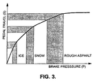
- Fig. 3 the dependence of the pedal travel to brake pressure (s/f) characteristics from the condition of the road surface is shown for three different friction coefficients (ICE, SNOW, ROUGH ROAD). From this it follows that the lower is the friction coefficient, the lower are the locking pressure and the corresponding pedal travel and vice versa.
Landscapes
- Engineering & Computer Science (AREA)
- Transportation (AREA)
- Mechanical Engineering (AREA)
- Physics & Mathematics (AREA)
- Fluid Mechanics (AREA)
- Regulating Braking Force (AREA)
Claims (4)
- Système de freinage électro-hydraulique du type qui est capable de fonctionner dans un mode de freinage à commande électronique dans lequel la pression hydraulique est appliquée aux dispositifs de freinage (18a, 18b, 18c, 18d) au niveau des roues du véhicule, en proportion avec la demande de freinage faite par le conducteur et telle qu'elle est détectée électroniquement au niveau d'une pédale de frein (10), dans un mode à commande mécanique dans lequel la pression hydraulique est appliquée aux dispositifs de freinage (18a, 18b, 18c, 18d) au niveau des roues du véhicule par l'intermédiaire d'un maître-cylindre (34) lequel est accouplé mécaniquement à la pédale de frein (10) et également dans un mode ABS dans lequel les pressions de freinage au niveau des roues individuelles sont commandées en fonction, entre autres, du comportement de rotation détecté sur les roues du véhicule, et qui inclut un simulateur de déplacement hydraulique (38) lequel est raccordé hydrauliquement au maître-cylindre (34) par l'intermédiaire d'une soupape d'isolement à commande électrique (36) afin de procurer au conducteur une meilleure sensation par le biais de la pédale de frein dans le mode de fonctionnement à commande mécanique, caractérisé en ce que la soupape d'isolement du simulateur de déplacement (36) est agencée de façon à être fermée lorsque le mode ABS est actif.
- Système, selon la revendication 1, dans lequel la fermeture de la soupape d'isolement du simulateur de déplacement (36) est agencée de façon à être retardée jusqu'à ce que deux roues du véhicule au moins soient pilotées par la commande ABS.
- Système, selon la revendication 1 ou 2, dans lequel lorsque la soupape d'isolement du simulateur de déplacement (36) se ferme pour la première fois, la pression du maître-cylindre sera mémorisée, la valeur ainsi mémorisée étant utilisée ultérieurement pour commander la réouverture de la soupape.
- Système, selon la revendication 3, dans lequel la soupape (36) est agencée de façon à rester fermée jusqu'à ce que la pression du maître-cylindre descende en dessous de la pression mémorisée et/ou jusqu'à ce que moins de deux roues restent sous le pilotage de la commande ABS.
Applications Claiming Priority (2)
| Application Number | Priority Date | Filing Date | Title |
|---|---|---|---|
| GB9825890A GB2344143B (en) | 1998-11-27 | 1998-11-27 | Pedal travel limitation in electro-hydraulic (ehb) braking systems |
| GB9825890 | 1998-11-27 |
Publications (3)
| Publication Number | Publication Date |
|---|---|
| EP1004492A2 EP1004492A2 (fr) | 2000-05-31 |
| EP1004492A3 EP1004492A3 (fr) | 2002-04-10 |
| EP1004492B1 true EP1004492B1 (fr) | 2006-01-04 |
Family
ID=10843070
Family Applications (1)
| Application Number | Title | Priority Date | Filing Date |
|---|---|---|---|
| EP99309338A Expired - Lifetime EP1004492B1 (fr) | 1998-11-27 | 1999-11-23 | Limitation de course de pédale pour systèmes de freinage électro-hydrauliques |
Country Status (4)
| Country | Link |
|---|---|
| US (1) | US6345871B1 (fr) |
| EP (1) | EP1004492B1 (fr) |
| DE (1) | DE69929295T2 (fr) |
| GB (1) | GB2344143B (fr) |
Families Citing this family (15)
| Publication number | Priority date | Publication date | Assignee | Title |
|---|---|---|---|---|
| GB2349676B (en) * | 1999-05-05 | 2003-04-23 | Lucas Ind Plc | Improved back-up braking in vehicle braking systems |
| US6957870B2 (en) * | 1999-12-24 | 2005-10-25 | Toyota Jidosha Kabushiki Kaisha | Braking pressure control apparatus capable of switching between two brake operating states using power-operated and manually operated pressure sources, respectively |
| JP2004528214A (ja) * | 2000-09-27 | 2004-09-16 | コンティネンタル・テーベス・アクチエンゲゼルシヤフト・ウント・コンパニー・オッフェネ・ハンデルスゲゼルシヤフト | 車両操作装置用の操作ストロークシミュレータ |
| GB2367869B (en) * | 2000-10-14 | 2004-10-06 | Trw Ltd | Rear-axle demand for use with front push-through in electrohydraulic (EHB) braking systems |
| DE102004027508A1 (de) * | 2004-06-04 | 2005-12-22 | Robert Bosch Gmbh | Hydraulische Bremsanlage und Verfahren zur Beeinflussung einer hydraulischen Bremsanlage |
| JP4333713B2 (ja) * | 2006-08-25 | 2009-09-16 | トヨタ自動車株式会社 | ブレーキ制御装置 |
| KR20090090452A (ko) * | 2008-02-21 | 2009-08-26 | 주식회사 만도 | 시뮬레이션 기능을 가진 전자제어식 브레이크 시스템 |
| DE102012223898B4 (de) * | 2012-01-02 | 2025-10-02 | Ford Global Technologies, Llc | Verfahren zum Betreiben eines hydraulischen Bremssystems eines Kraftfahrzeugs sowie hydraulisches Bremssystem |
| US10632979B2 (en) | 2014-06-30 | 2020-04-28 | Freni Brembo S.P.A. | Automatically controlled braking system for vehicles and method of actuating and controlling a braking system for vehicles |
| JP6432484B2 (ja) * | 2015-10-20 | 2018-12-05 | 株式会社アドヴィックス | 車両の制動制御装置 |
| KR102554822B1 (ko) | 2016-08-24 | 2023-07-12 | 에이치엘만도 주식회사 | 차량 제어 장치 및 그 제어 방법 |
| US10800389B2 (en) | 2018-08-31 | 2020-10-13 | Robert Bosch Gmbh | Haptic feedback for decoupled brake system |
| KR102492488B1 (ko) * | 2018-10-22 | 2023-01-27 | 현대모비스 주식회사 | 차량의 제동 제어 장치 및 방법 |
| CN113665546B (zh) * | 2021-10-08 | 2022-04-08 | 湖南工程学院 | 制动系统abs路感补偿与行程模拟耦合控制装置及方法 |
| DE102022122523A1 (de) * | 2022-09-06 | 2024-03-07 | Dr. Ing. H.C. F. Porsche Aktiengesellschaft | Verfahren zur Optimierung der Dosierbarkeit der Bremskraft bei einer ABS-Bremsung |
Family Cites Families (11)
| Publication number | Priority date | Publication date | Assignee | Title |
|---|---|---|---|---|
| DE3131856A1 (de) * | 1981-08-12 | 1983-02-24 | Robert Bosch Gmbh, 7000 Stuttgart | Fahrzeugbremsanlage |
| JPS6364858A (ja) * | 1986-09-04 | 1988-03-23 | Sumitomo Electric Ind Ltd | 車両のブレ−キ圧力制御装置 |
| DE4102497C1 (fr) * | 1991-01-29 | 1992-05-07 | Mercedes-Benz Aktiengesellschaft, 7000 Stuttgart, De | |
| WO1993000236A1 (fr) | 1991-06-26 | 1993-01-07 | Allied-Signal Inc. | Systeme de freinage electrohydraulique avec pression de freinage de secours |
| DE4340467C2 (de) * | 1993-11-27 | 2002-03-14 | Bosch Gmbh Robert | Mit Fremdkraft arbeitende hydraulische Fahrzeugbremsanlage |
| DE19543583C1 (de) * | 1995-11-22 | 1997-02-06 | Daimler Benz Ag | Bremsdruck-Steuerungseinrichtung für ein Straßenfahrzeug mit elektrohydraulischer Mehrkreis-Bremsanlage |
| DE19548248A1 (de) * | 1995-12-22 | 1997-06-26 | Bosch Gmbh Robert | Verfahren und Vorrichtung zur Steuerung einer Pumpe eines elektrohydraulischen Bremssystems |
| US5941608A (en) | 1996-03-07 | 1999-08-24 | Kelsey-Hayes Company | Electronic brake management system with manual fail safe |
| DE19655276B4 (de) | 1996-04-25 | 2008-04-30 | Lucas Industries Plc, Solihull | Elektrohydraulische Bremsanlage |
| US6213572B1 (en) * | 1997-01-31 | 2001-04-10 | Kelsey-Hayes Company | Electro-hydraulic brake system with electronic pedal simulation |
| DE69834480T2 (de) * | 1997-03-06 | 2006-09-21 | Kelsey-Hayes Co., Livonia | Gerät und Verfahren zur Bereitstellung eines Bremssteuersignals |
-
1998
- 1998-11-27 GB GB9825890A patent/GB2344143B/en not_active Revoked
-
1999
- 1999-11-23 EP EP99309338A patent/EP1004492B1/fr not_active Expired - Lifetime
- 1999-11-23 DE DE69929295T patent/DE69929295T2/de not_active Expired - Fee Related
- 1999-11-24 US US09/448,119 patent/US6345871B1/en not_active Expired - Fee Related
Also Published As
| Publication number | Publication date |
|---|---|
| DE69929295T2 (de) | 2006-08-17 |
| GB9825890D0 (en) | 1999-01-20 |
| DE69929295D1 (de) | 2006-03-30 |
| GB2344143A (en) | 2000-05-31 |
| GB2344143B (en) | 2003-01-22 |
| EP1004492A3 (fr) | 2002-04-10 |
| US6345871B1 (en) | 2002-02-12 |
| EP1004492A2 (fr) | 2000-05-31 |
Similar Documents
| Publication | Publication Date | Title |
|---|---|---|
| US5611606A (en) | Vehicle brake-pressure control device | |
| EP1175320B1 (fr) | Freinage de secours ameliore dans les systemes de freinage pour vehicules | |
| EP1185448B1 (fr) | Freinage de secours dans un systeme de freinage electrohydraulique (ehb) | |
| US6086515A (en) | Process and system for retaining a vehicle on an inclined roadway | |
| US5375919A (en) | Anti-skid control method | |
| US4699436A (en) | Brake system for automotive vehicles | |
| US6957870B2 (en) | Braking pressure control apparatus capable of switching between two brake operating states using power-operated and manually operated pressure sources, respectively | |
| EP1004492B1 (fr) | Limitation de course de pédale pour systèmes de freinage électro-hydrauliques | |
| EP0566344B1 (fr) | Systèmes hydrauliques de freinage pour véhicules | |
| GB2229238A (en) | Vehicle anti-lock brake systems | |
| EP1016574A2 (fr) | Avertissement du conducteur d'un mauvais fonctionnement du freinage dans un système électro - hydraulique | |
| US20110029215A1 (en) | Method for controlling a vehicle brake system, the slip of which can be regulated electronically | |
| US5190358A (en) | Antilock brake system for providing different brake pressures to front and rear wheel circuits | |
| EP0796184B1 (fr) | Perfectionnements des systemes de freinage hydraulique de vehicules | |
| JP2001520144A (ja) | 自動車制御システムの制御動作を改良する方法 | |
| JPH02220954A (ja) | 自動車用流体ブレーキ回路 | |
| JPH09512764A (ja) | 自動車用流体ブレーキ回路のためのハイブリッド構造をもつ圧力調整装置 | |
| US4898432A (en) | Adaptive braking system having hydraulic booster and pump-back system | |
| JP2008500217A (ja) | 流体作動の車両ブレーキシステムによる車両制動方法および車両ブレーキシステム | |
| US5472267A (en) | Flow control valve and pressure regulator for an anti-lock braking system | |
| US20030205928A1 (en) | Optimised brake-apply sequence in electro-hydraulic (EHB) braking systems | |
| US5971502A (en) | Secondary braking control | |
| EP1170186A2 (fr) | Système de freinage électro-hydraulique | |
| GB2240597A (en) | Improvements in hydraulic anti-lock braking systems for vehicles |
Legal Events
| Date | Code | Title | Description |
|---|---|---|---|
| PUAI | Public reference made under article 153(3) epc to a published international application that has entered the european phase |
Free format text: ORIGINAL CODE: 0009012 |
|
| AK | Designated contracting states |
Kind code of ref document: A2 Designated state(s): AT BE CH CY DE DK ES FI FR GB GR IE IT LI LU MC NL PT SE Kind code of ref document: A2 Designated state(s): DE ES FR GB IT |
|
| AX | Request for extension of the european patent |
Free format text: AL;LT;LV;MK;RO;SI |
|
| PUAL | Search report despatched |
Free format text: ORIGINAL CODE: 0009013 |
|
| AK | Designated contracting states |
Kind code of ref document: A3 Designated state(s): AT BE CH CY DE DK ES FI FR GB GR IE IT LI LU MC NL PT SE |
|
| AX | Request for extension of the european patent |
Free format text: AL;LT;LV;MK;RO;SI |
|
| 17P | Request for examination filed |
Effective date: 20021001 |
|
| AKX | Designation fees paid |
Free format text: DE ES FR GB IT |
|
| 17Q | First examination report despatched |
Effective date: 20030709 |
|
| GRAP | Despatch of communication of intention to grant a patent |
Free format text: ORIGINAL CODE: EPIDOSNIGR1 |
|
| GRAS | Grant fee paid |
Free format text: ORIGINAL CODE: EPIDOSNIGR3 |
|
| GRAA | (expected) grant |
Free format text: ORIGINAL CODE: 0009210 |
|
| AK | Designated contracting states |
Kind code of ref document: B1 Designated state(s): DE ES FR GB IT |
|
| PG25 | Lapsed in a contracting state [announced via postgrant information from national office to epo] |
Ref country code: IT Free format text: LAPSE BECAUSE OF FAILURE TO SUBMIT A TRANSLATION OF THE DESCRIPTION OR TO PAY THE FEE WITHIN THE PRESCRIBED TIME-LIMIT;WARNING: LAPSES OF ITALIAN PATENTS WITH EFFECTIVE DATE BEFORE 2007 MAY HAVE OCCURRED AT ANY TIME BEFORE 2007. THE CORRECT EFFECTIVE DATE MAY BE DIFFERENT FROM THE ONE RECORDED. Effective date: 20060104 |
|
| REG | Reference to a national code |
Ref country code: GB Ref legal event code: FG4D |
|
| REF | Corresponds to: |
Ref document number: 69929295 Country of ref document: DE Date of ref document: 20060330 Kind code of ref document: P |
|
| PG25 | Lapsed in a contracting state [announced via postgrant information from national office to epo] |
Ref country code: ES Free format text: LAPSE BECAUSE OF FAILURE TO SUBMIT A TRANSLATION OF THE DESCRIPTION OR TO PAY THE FEE WITHIN THE PRESCRIBED TIME-LIMIT Effective date: 20060415 |
|
| ET | Fr: translation filed | ||
| PGFP | Annual fee paid to national office [announced via postgrant information from national office to epo] |
Ref country code: GB Payment date: 20061004 Year of fee payment: 8 |
|
| PGFP | Annual fee paid to national office [announced via postgrant information from national office to epo] |
Ref country code: FR Payment date: 20061103 Year of fee payment: 8 |
|
| PLBE | No opposition filed within time limit |
Free format text: ORIGINAL CODE: 0009261 |
|
| STAA | Information on the status of an ep patent application or granted ep patent |
Free format text: STATUS: NO OPPOSITION FILED WITHIN TIME LIMIT |
|
| PGFP | Annual fee paid to national office [announced via postgrant information from national office to epo] |
Ref country code: IT Payment date: 20061130 Year of fee payment: 8 Ref country code: DE Payment date: 20061130 Year of fee payment: 8 |
|
| 26N | No opposition filed |
Effective date: 20061005 |
|
| REG | Reference to a national code |
Ref country code: GB Ref legal event code: 732E |
|
| GBPC | Gb: european patent ceased through non-payment of renewal fee |
Effective date: 20071123 |
|
| PG25 | Lapsed in a contracting state [announced via postgrant information from national office to epo] |
Ref country code: DE Free format text: LAPSE BECAUSE OF NON-PAYMENT OF DUE FEES Effective date: 20080603 |
|
| REG | Reference to a national code |
Ref country code: FR Ref legal event code: ST Effective date: 20080930 |
|
| PG25 | Lapsed in a contracting state [announced via postgrant information from national office to epo] |
Ref country code: GB Free format text: LAPSE BECAUSE OF NON-PAYMENT OF DUE FEES Effective date: 20071123 |
|
| PG25 | Lapsed in a contracting state [announced via postgrant information from national office to epo] |
Ref country code: FR Free format text: LAPSE BECAUSE OF NON-PAYMENT OF DUE FEES Effective date: 20071130 |
|
| PG25 | Lapsed in a contracting state [announced via postgrant information from national office to epo] |
Ref country code: IT Free format text: LAPSE BECAUSE OF NON-PAYMENT OF DUE FEES Effective date: 20071123 |