EP1004758B1 - Moteur à combustion interne avec des cylindres en V - Google Patents
Moteur à combustion interne avec des cylindres en V Download PDFInfo
- Publication number
- EP1004758B1 EP1004758B1 EP99123515A EP99123515A EP1004758B1 EP 1004758 B1 EP1004758 B1 EP 1004758B1 EP 99123515 A EP99123515 A EP 99123515A EP 99123515 A EP99123515 A EP 99123515A EP 1004758 B1 EP1004758 B1 EP 1004758B1
- Authority
- EP
- European Patent Office
- Prior art keywords
- power transmission
- crankshaft
- transmission belt
- chain
- internal combustion
- Prior art date
- Legal status (The legal status is an assumption and is not a legal conclusion. Google has not performed a legal analysis and makes no representation as to the accuracy of the status listed.)
- Expired - Lifetime
Links
- 238000002485 combustion reaction Methods 0.000 title claims description 19
- 230000005540 biological transmission Effects 0.000 claims description 68
- 230000002452 interceptive effect Effects 0.000 claims description 3
- 230000001105 regulatory effect Effects 0.000 claims description 2
- 238000010276 construction Methods 0.000 description 17
- 238000007796 conventional method Methods 0.000 description 3
- XLYOFNOQVPJJNP-UHFFFAOYSA-N water Substances O XLYOFNOQVPJJNP-UHFFFAOYSA-N 0.000 description 3
- 238000004880 explosion Methods 0.000 description 2
- 238000012986 modification Methods 0.000 description 2
- 230000004048 modification Effects 0.000 description 2
- 238000005304 joining Methods 0.000 description 1
- 238000004519 manufacturing process Methods 0.000 description 1
- 238000003825 pressing Methods 0.000 description 1
- 230000002265 prevention Effects 0.000 description 1
Images



Classifications
-
- F—MECHANICAL ENGINEERING; LIGHTING; HEATING; WEAPONS; BLASTING
- F01—MACHINES OR ENGINES IN GENERAL; ENGINE PLANTS IN GENERAL; STEAM ENGINES
- F01L—CYCLICALLY OPERATING VALVES FOR MACHINES OR ENGINES
- F01L1/00—Valve-gear or valve arrangements, e.g. lift-valve gear
- F01L1/02—Valve drive
- F01L1/024—Belt drive
-
- F—MECHANICAL ENGINEERING; LIGHTING; HEATING; WEAPONS; BLASTING
- F02—COMBUSTION ENGINES; HOT-GAS OR COMBUSTION-PRODUCT ENGINE PLANTS
- F02B—INTERNAL-COMBUSTION PISTON ENGINES; COMBUSTION ENGINES IN GENERAL
- F02B75/00—Other engines
- F02B75/16—Engines characterised by number of cylinders, e.g. single-cylinder engines
- F02B75/18—Multi-cylinder engines
- F02B75/22—Multi-cylinder engines with cylinders in V, fan, or star arrangement
-
- F—MECHANICAL ENGINEERING; LIGHTING; HEATING; WEAPONS; BLASTING
- F02—COMBUSTION ENGINES; HOT-GAS OR COMBUSTION-PRODUCT ENGINE PLANTS
- F02B—INTERNAL-COMBUSTION PISTON ENGINES; COMBUSTION ENGINES IN GENERAL
- F02B75/00—Other engines
- F02B75/16—Engines characterised by number of cylinders, e.g. single-cylinder engines
- F02B75/18—Multi-cylinder engines
- F02B2075/1804—Number of cylinders
- F02B2075/1832—Number of cylinders eight
-
- F—MECHANICAL ENGINEERING; LIGHTING; HEATING; WEAPONS; BLASTING
- F02—COMBUSTION ENGINES; HOT-GAS OR COMBUSTION-PRODUCT ENGINE PLANTS
- F02B—INTERNAL-COMBUSTION PISTON ENGINES; COMBUSTION ENGINES IN GENERAL
- F02B2275/00—Other engines, components or details, not provided for in other groups of this subclass
- F02B2275/18—DOHC [Double overhead camshaft]
Definitions
- the crankshaft comprises a plane crank in which axial centers of all crank pins for relative cylinders are located in a common plane
- the V-shaped cylinder banks comprise a cylinder block in which an upper block and a lower block thereof are separated from each other with a substantially horizontal plane passing through a center of the crankshaft
- one of the pair of balancer shafts which is located in the lower block side is connected to the crankshaft through the third endless power transmission belts
- the other of the pair of balancer shafts which is located in the upper block side is connected to the one of the pair of balancer shafts by intermeshing the pair of third gears with each other in such a manner that the pair of balancer shafts rotate in opposite directions to each other.
- This engine E comprises an upper block 1 provided with a pair of cylinder banks whose included angle is 90 degrees, a lower block 2 joined to a lower surface of the upper block 1, an oil pan 3 joined to a lower surface of the lower block 2 and cylinder heads 4a, 4b joined, respectively, to upper surfaces of both the cylinder banks of the upper block 1.
- two camshafts 5a, 5b are provided above the respective cylinder heads 4a, 4b, and these camshafts 5a, 5b are covered, respectively, with head covers 6a, 6b joined to upper surfaces of the cylinder heads 4a, 4b.
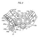
- a crank sprocket 10 is securely fitted over the crankshaft 7 at a position axially inwardly of the crank pulley, and a driver pinion 11 is securely fitted on the crankshaft 7 at a position axially inwardly of the crank sprocket 10.
- the balancer shafts 16 are provided on a tensioned side of the silent chain 19 relative to the rotational direction of the crankshaft 7. This can minimize a relative phase angle error between the crankshaft 7 and the balancer shafts 16.
- Chain tensioners 22 to 24 in which a pressing force is automatically adjusted by a hydraulic plunger and run-out prevention chain guides 25 to 28 are attached individually to the silent chains 15a, 15b wound around the cam sprockets 14a, 14b of the respective camshafts 5 of both of the cylinder banks and the silent chain 19 wound around the balancer shaft sprocket 17 and the pump sprocket 18.
- These chain tensioners 22 to 24 and the chain guides 25 to 28 are each fixed with a bolt or the like to a suitable position on an end face of the upper block 1, lower block 2, oil pan 3 and cylinder heads 4a, 4b on the crank pulley side thereof.
- these integrated chain guides 25, 28 are constructed so as to cover the balancer shaft 16a on the upper block side from where they are located, but since their positions in the axial direction of the crankshaft substantially coincide with the end of the balancer shaft 16a, those chain guides can be utilized as a thrust bearing for the balancer shaft 16a. In this case, a thrust plate can be omitted, and oil flowing out from the balancer shaft 16a can be supplied to the silent chain 19 via the integrated chain guides 25, 28.
- the integrated guide members are provided on the axis of the blancer shaft supported on the cylinder block above the balancer shaft driving sub-chain 19 at the end of the balancer shaft, whereby the guide members can be provided by effectively utilizing the space on the axis of the balancer shaft, and oil can be supplied to the sub-chain from the balancer shaft side via these guide members, this simplifying the construction othereof.
- the left and right driven pinions 12a, 12b are in mesh engagement with the driver pinion 11 in such a manner that the mesh engagement of the driven pinions with the driver pinion shifts half a pitch in the respective cylinder banks.
- This half-a-pitch shifting mesh engagement of the left and right driven pinions 12a, 12b with the driver pinion 11 becomes clear when comparing mesh engagement portions of those driven pinions and driver pinion along straight lines a, b connecting centers of the respective gears.
- the gear assembly 46 in which the driven pinions 12a, 12b and the small sprockets 13a, 13b are integrally provided is common over left and right in use, and an assembling angle mark 47 is engraved in an end face of the gear assembly.
- a letter R or L is affixed to this assembling angle mark 47, and the gear assembly 46 positioned right-hand side as viewed from the driver's seat (an left-hand side assembly in Fig.
- the chain is used as the endless power transmission belt, but a belt may be used instead thereof.
- the sprockets used in the above construction may be replaced with pulleys.
- the balancer device for a V-shaped engine provided with a plane crank in which centers of all crank pins are located on the same plane and having a bank defining angle of 90 degrees
- the first and second gears 12 are interposed, respectively, between the first and second endless power transmission belts each for driving the camshafts above the cylinder head of each of the V-shaped cylinder banks and the crankshaft 7,
- the pair of balancer shafts 16a, 16b are provided at symmetrical positions with respect to the separating plane acting as a center therebetween where the upper block 1 and the lower block 2 of the cylinder block are separated from each other from the horizontal plane passing through the center of the crankshaft 7 in such a manner that the axes of the pair of balancer shafts 16a, 16b are parallel with the crank shaft 7 so that the balancer shafts 16a, 16b rotate in opposite directions to each other, and wherein the crankshaft 7 and the balancer shaft 16b on the lower block 2 side are connected to each other by
- a relative phase angle error between the crankshaft 7 and both of the balancer shafts 16 can be minimized and a dead space formed therebetween can be utilized effectively by disposing the balancer shaft 16a on the upper block 1 side on the tensioned side of the third power transmission belt, and providing the guide member 28 for the third power transmission belt and the support portion 28a therefor between the balancer shaft 16a on the upper block 1 side and the tensioned side of the third power transmission belt.
- First and second gears are interposed, respectively, between first and second endless power transmission belts each for driving a camshaft of a cylinder head of each of V-shaped cylinder banks and a crankshaft 7.
- a pair of balancer shafts are provided at symmetrical positions with respect to a separating plane acting as a center therebetween where an upper block and a lower block of a cylinder block are separated from each other from a horizontal plane passing through a center of the crankshaft in such a manner that axes of the pair of balancer shafts become parallel with the crank shaft.
- the crankshaft and the balancer shaft on the lower block side are connected to each other by means of a third endless power transmission belt.
- the balancer shafts are connected to each other by means of third gears, so that the pair of balancer shafts are driven to rotate in the opposite directions. Accordingly, the first and second endless power transmission belts and the third endless power transmission belt are prevented from overlapping each other in an axial direction of the crankshaft.
- the respective endless power transmission belts and the respective gears are disposed, respectively, on planes each intersecting at right angles with the axis of the crankshaft, whereby the expansion of the engine in the axial direction of the crankshaft can be prevented.
Landscapes
- Engineering & Computer Science (AREA)
- Mechanical Engineering (AREA)
- General Engineering & Computer Science (AREA)
- Chemical & Material Sciences (AREA)
- Combustion & Propulsion (AREA)
- Valve-Gear Or Valve Arrangements (AREA)
- Devices For Conveying Motion By Means Of Endless Flexible Members (AREA)
Claims (11)
- Moteur à combustion interne en V comportant un dispositif d'équilibrage, ledit moteur comprenant :un vilebrequin ;des groupes de cylindres en V comportant un groupe définissant un angle de 90° ;une première courroie de transmission de puissance sans fin pour entraíner un premier élément d'arbre à cames qui est prévu au-dessus d'une culasse d'un desdits groupes de cylindres en V ;un premier engrenage interposé entre ladite première courroie de transmission de puissance sans fin et ledit vilebrequin ;une deuxième courroie de transmission de puissance sans fin pour entraíner un deuxième élément d'arbre à cames qui est prévu au-dessus d'une culasse de l'autre desdits groupes de cylindres en V ;un deuxième engrenage interposé entre ladite deuxième courroie de transmission de puissance sans fin et ledit vilebrequin ;deux arbres d'équilibrage tournant dans des directions opposées l'un par rapport à l'autre et s'étendant parallèlement à un axe dudit vilebrequin ;deux troisièmes engrenages entraínant, respectivement, lesdits deux arbres d'équilibrage ; etune troisième courroie de transmission de puissance pour relier ledit vilebrequin et l'un desdits arbres d'équilibrage, ladite troisième courroie de transmission de puissance étant disposée à une position à l'extérieur d'une zone interférant avec lesdites première et deuxième courroies de transmission de puissance sans fin dans un plan perpendiculaire à la direction axiale dudit vilebrequin.
- Moteur à combustion interne en V selon la revendication 1, dans lequel :ledit vilebrequin comprend un bras de manivelle plan dans lequel les centres axiaux de tous les manetons pour les cylindres associés sont situés dans un plan commun,lesdits groupes de cylindres en V comprennent un bloc-cylindres dans lequel un bloc supérieur et un bloc inférieur de celui-ci sont séparés l'un de l'autre par un plan sensiblement horizontal passant par un centre dudit vilebrequin,l'un desdits deux arbres d'équilibrage qui est situé du côté du bloc inférieur est relié audit vilebrequin par l'intermédiaire de ladite troisième courroie de transmission de puissance sans fin, etl'autre desdits deux arbres d'équilibrage qui est situé du côté du bloc supérieur est relié audit premier desdits deux arbres d'équilibrage par l'engrenage entre eux desdits deux troisièmes engrenages de manière à ce que lesdits deux arbres d'équilibrage tournent dans des directions opposées l'un par rapport à l'autre.
- Moteur à combustion interne en V selon l'une quelconque des revendications 1 ou 2, dans lequel lesdites première à troisième courroies de transmission de puissance sont sensiblement disposées dans un premier plan croisant à angle droit un axe dudit vilebrequin, et
lesdits premier à troisième engrenages sont disposés dans un deuxième plan croisant à angle droit l'axe dudit vilebrequin. - Moteur à combustion interne en V selon l'une quelconque des revendications 1 à 3, dans lequel l'un desdits arbres d'équilibrage disposé du côté du bloc supérieur est disposé d'un côté tendu de ladite troisième courroie de transmission de puissance, et
ledit moteur comprend en outre un élément de guidage pour guider ladite troisième courroie de transmission de puissance, ledit élément de guidage étant supporté au niveau d'une partie de support de celui-ci qui est disposée entre l'arbre d'équilibrage côté bloc supérieur et le côté tendu de ladite troisième courroie de transmission de puissance. - Moteur à combustion interne en V selon l'une quelconque des revendications 1 à 4, dans lequel ledit côté de tension de ladite troisième courroie de transmission de puissance est face à un côté de tension de ladite première courroie de transmission de puissance, ledit élément de guidage guide à la fois ladite première courroie de transmission de puissance et ladite troisième courroie de transmission de puissance, et ledit élément de guidage est disposé dudit côté de tension de ladite première courroie de transmission de puissance et également dudit côté de tension de ladite troisième courroie de transmission de puissance.
- Moteur à combustion interne en V selon l'une quelconque des revendications 1 à 4, dans lequel ledit côté de tension de ladite troisième courroie de transmission de puissance et ledit côté de tension de ladite première courroie de transmission de puissance sont sensiblement disposés dans un troisième plan croisant à angle droit l'axe dudit vilebrequin, ledit élément de guidage guide à la fois ladite première courroie de transmission de puissance et ladite troisième courroie de transmission de puissance, et ledit élément de guidage est disposé dudit côté de tension de ladite première courroie de transmission de puissance et également dudit côté de tension de ladite troisième courroie de transmission de puissance.
- Moteur à combustion interne en V selon l'une quelconque des revendications 5 ou 6, dans lequel ledit élément de guidage est prévu à une position croisant un axe de l'un desdits deux arbres d'équilibrage qui est disposé au-dessus de ladite troisième courroie de transmission de puissance.
- Moteur à combustion interne en V selon la revendication 7, dans lequel la force de poussée de l'un desdits arbres d'équilibrage est reçue par ledit élément de guidage.
- Moteur à combustion interne en V selon la revendication 1, dans lequel ledit vilebrequin est relié à un pignon d'entraínement qui est amené en prise par engrènement à la fois avec lesdits premier et deuxième engrenages dans un état dans lequel les mises en prise par engrènement desdits premier et deuxième engrenages avec ledit pignon d'entraínement sont décalées d'un demi pas l'une par rapport à l'autre.
- Moteur à combustion interne en V selon la revendication 9, dans lequel :chacun desdits premier et deuxième engrenages comprend l'une d'une roue dentée et d'un poulie dentée,chacune desdites première et deuxième courroies de transmission de puissance comprend l'une d'une chaíne et d'une courroie dentée,l'une de ladite roue dentée et de ladite poulie dentée est amenée en prise par engrènement avec l'une desdites chaíne et courroie dentée dans un état dans lequel les mises en prise par engrènement de ladite une desdites roue dentée et poulie dentée avec ladite une desdites chaíne et courroie dentée sont décalées d'un demi pas l'une par rapport à l'autre, etune marque d'angle d'assemblage pour régler un angle d'assemblage pour chaque groupe de cylindres est prévue sur un ensemble d'engrenages dans lequel l'une de ladite roue dentée et de ladite poulie dentée est prévue d'un seul tenant avec l'un desdits premier et deuxième engrenages.
- Moteur à combustion interne en V selon la revendication 1, dans lequel :ledit vilebrequin est relié à un pignon d'entraínement qui est amené en prise par engrènement à la fois avec lesdits premier et deuxième engrenages,chacun desdits premier et deuxième engrenages comprend l'une d'une roue dentée et d'un poulie dentée,chacune desdites première et deuxième courroies de transmission de puissance comprend l'une d'une chaíne et d'une courroie dentée, etl'une de ladite roue dentée et de ladite poulie dentée est amenée en prise par engrènement avec l'une desdites chaíne et courroie dentée dans un état dans lequel les mises en prise par engrènement de ladite une desdites roue dentée et poulie dentée avec ladite une desdites chaíne et courroie dentée sont décalées d'un demi pas l'une par rapport à l'autre.
Applications Claiming Priority (6)
| Application Number | Priority Date | Filing Date | Title |
|---|---|---|---|
| JP33760998 | 1998-11-27 | ||
| JP10337609A JP2000161440A (ja) | 1998-11-27 | 1998-11-27 | 4サイクルv型8気筒エンジン用バランス装置 |
| JP37232398 | 1998-12-28 | ||
| JP10372323A JP2000199438A (ja) | 1998-12-28 | 1998-12-28 | 4サイクルv型エンジンのカム駆動構造 |
| JP37228298A JP3955161B2 (ja) | 1998-12-28 | 1998-12-28 | サブチェーン付きエンジン |
| JP37228298 | 1998-12-28 |
Publications (3)
| Publication Number | Publication Date |
|---|---|
| EP1004758A2 EP1004758A2 (fr) | 2000-05-31 |
| EP1004758A3 EP1004758A3 (fr) | 2001-04-18 |
| EP1004758B1 true EP1004758B1 (fr) | 2004-08-25 |
Family
ID=27340841
Family Applications (1)
| Application Number | Title | Priority Date | Filing Date |
|---|---|---|---|
| EP99123515A Expired - Lifetime EP1004758B1 (fr) | 1998-11-27 | 1999-11-25 | Moteur à combustion interne avec des cylindres en V |
Country Status (4)
| Country | Link |
|---|---|
| US (1) | US6213072B1 (fr) |
| EP (1) | EP1004758B1 (fr) |
| CA (1) | CA2290729C (fr) |
| DE (1) | DE69919664T2 (fr) |
Families Citing this family (16)
| Publication number | Priority date | Publication date | Assignee | Title |
|---|---|---|---|---|
| CA2323383C (fr) * | 1999-10-15 | 2003-12-23 | Honda Giken Kogyo Kabushiki Kaisha | Moteur a deux cylindres en v a arbre a came en tete |
| US6941914B2 (en) * | 2002-04-15 | 2005-09-13 | Tecumseh Products Company | Internal combustion engine |
| JP2006144651A (ja) * | 2004-11-18 | 2006-06-08 | Yamaha Marine Co Ltd | 内燃機関における動弁装置 |
| JP4405377B2 (ja) * | 2004-12-22 | 2010-01-27 | 本田技研工業株式会社 | V型エンジンのテンショナリフタ取付け構造 |
| US7258093B2 (en) * | 2005-12-01 | 2007-08-21 | Chriswell Shawn D | Concave combustion chamber |
| DE102006013941A1 (de) * | 2006-03-17 | 2007-09-20 | Weber Technology Ag | V-Motor mit Nebenwellen |
| US20080261738A1 (en) * | 2007-04-17 | 2008-10-23 | Joseph Stout | Chain transmission system |
| US20090293822A1 (en) * | 2008-05-28 | 2009-12-03 | Honda Motor Co., Ltd. | General-purpose v-type engine |
| JP2011163252A (ja) * | 2010-02-12 | 2011-08-25 | Honda Motor Co Ltd | エンジン |
| DE102010025002A1 (de) * | 2010-06-24 | 2011-12-29 | Fev Motorentechnik Gmbh | Arbeitsmaschine |
| JP5711064B2 (ja) * | 2011-07-26 | 2015-04-30 | 本田技研工業株式会社 | バランサ付き内燃機関 |
| DE102013010585A1 (de) * | 2013-06-26 | 2014-12-31 | AFS Fördertechnik GmbH | Kraftübertragungselement zum Rollenantrieb bei einem Rollenförderer |
| US9739180B2 (en) * | 2015-08-07 | 2017-08-22 | GM Global Technology Operations LLC | Variable tensioning for engine camshaft drive |
| CN106051077A (zh) * | 2016-07-29 | 2016-10-26 | 辽宁正时动力传动科技有限公司 | 一种v型汽油发动机正时齿形链传动系统 |
| JP2019532217A (ja) * | 2016-10-24 | 2019-11-07 | アカーテース パワー,インク. | 対向ピストンエンジン用ギアトレイン |
| CN111684146B (zh) | 2017-12-13 | 2022-08-05 | 康明斯公司 | 远程安装的中间齿轮 |
Family Cites Families (10)
| Publication number | Priority date | Publication date | Assignee | Title |
|---|---|---|---|---|
| DE1188364B (de) * | 1962-07-28 | 1965-03-04 | Kloeckner Humboldt Deutz Ag | Hubkolbenbrennkraftmaschine mit Massenausgleich zweiter Ordnung durch Gegengewichtspaare |
| US4683849A (en) * | 1984-11-20 | 1987-08-04 | Brown Arthur E | Reciprocating multicylinder vee machines with secondary counterbalancers |
| JPS62233423A (ja) | 1986-04-01 | 1987-10-13 | Mazda Motor Corp | V型エンジン |
| DE3625246A1 (de) * | 1986-07-25 | 1988-02-04 | Audi Ag | Hubkolben-v8-brennkraftmaschine |
| US5216989A (en) * | 1990-11-30 | 1993-06-08 | Mazda Motor Corporation | Apparatus for driving various devices by internal combustion engine |
| JPH04209927A (ja) * | 1990-11-30 | 1992-07-31 | Mazda Motor Corp | 内燃機関の補機部品駆動装置 |
| DE4238148C2 (de) * | 1992-11-12 | 1995-08-24 | Ford Werke Ag | Antrieb einer Ausgleichswelle an einer V-Brennkraftmaschine |
| JPH08193648A (ja) | 1995-01-12 | 1996-07-30 | Shinko Electric Co Ltd | 移動体の位置決め装置 |
| US5657728A (en) * | 1995-08-07 | 1997-08-19 | Ford Motor Company | Planar crankshaft balance system |
| US6109227A (en) * | 1998-09-17 | 2000-08-29 | Borgwarner Inc. | Torsionally compliant sprocket system for balance shaft drive |
-
1999
- 1999-11-24 US US09/448,495 patent/US6213072B1/en not_active Expired - Fee Related
- 1999-11-25 EP EP99123515A patent/EP1004758B1/fr not_active Expired - Lifetime
- 1999-11-25 DE DE69919664T patent/DE69919664T2/de not_active Expired - Fee Related
- 1999-11-26 CA CA002290729A patent/CA2290729C/fr not_active Expired - Fee Related
Also Published As
| Publication number | Publication date |
|---|---|
| DE69919664D1 (de) | 2004-09-30 |
| CA2290729C (fr) | 2006-02-14 |
| CA2290729A1 (fr) | 2000-05-27 |
| DE69919664T2 (de) | 2005-02-10 |
| EP1004758A3 (fr) | 2001-04-18 |
| US6213072B1 (en) | 2001-04-10 |
| EP1004758A2 (fr) | 2000-05-31 |
Similar Documents
| Publication | Publication Date | Title |
|---|---|---|
| EP1004758B1 (fr) | Moteur à combustion interne avec des cylindres en V | |
| US5216989A (en) | Apparatus for driving various devices by internal combustion engine | |
| US5860402A (en) | Oil pump drive for engine | |
| US5678516A (en) | Accessory drive arrangement for engine | |
| US5657728A (en) | Planar crankshaft balance system | |
| US5715784A (en) | Engine balancer shaft drive | |
| JPH1089147A (ja) | 内燃エンジンのシリンダヘッド構造 | |
| US6718934B2 (en) | Balancer structure for a V-type engine | |
| US5740768A (en) | Engine cam shaft drive arrangement | |
| JPH0666112A (ja) | V型エンジン | |
| EP0754879B1 (fr) | Moteur à combustion interne avec système d'équilibrage | |
| US5732667A (en) | Engine water pump drive | |
| JPH0718349B2 (ja) | 内燃機関の巻掛伝動装置 | |
| US20040016414A1 (en) | Engine | |
| JP3955161B2 (ja) | サブチェーン付きエンジン | |
| KR100570723B1 (ko) | 브이형 내연기관 | |
| JPH0666111A (ja) | エンジンの動力伝達装置 | |
| US6199525B1 (en) | Camshaft drive for engine | |
| MXPA99010966A (en) | Internal combustion engine in form d | |
| JPH059557Y2 (fr) | ||
| JP2790644B2 (ja) | V型エンジンの動弁装置 | |
| EP0661418B1 (fr) | Moteur à combustion interne | |
| JP2000199438A (ja) | 4サイクルv型エンジンのカム駆動構造 | |
| JP2704750B2 (ja) | 内燃機関のバランサ軸駆動装置 | |
| JPS61103025A (ja) | エンジンのバランサ装置 |
Legal Events
| Date | Code | Title | Description |
|---|---|---|---|
| PUAI | Public reference made under article 153(3) epc to a published international application that has entered the european phase |
Free format text: ORIGINAL CODE: 0009012 |
|
| AK | Designated contracting states |
Kind code of ref document: A2 Designated state(s): DE GB |
|
| AX | Request for extension of the european patent |
Free format text: AL;LT;LV;MK;RO;SI |
|
| PUAL | Search report despatched |
Free format text: ORIGINAL CODE: 0009013 |
|
| AK | Designated contracting states |
Kind code of ref document: A3 Designated state(s): AT BE CH CY DE DK ES FI FR GB GR IE IT LI LU MC NL PT SE |
|
| AX | Request for extension of the european patent |
Free format text: AL;LT;LV;MK;RO;SI |
|
| 17P | Request for examination filed |
Effective date: 20011015 |
|
| AKX | Designation fees paid |
Free format text: DE GB |
|
| GRAP | Despatch of communication of intention to grant a patent |
Free format text: ORIGINAL CODE: EPIDOSNIGR1 |
|
| GRAS | Grant fee paid |
Free format text: ORIGINAL CODE: EPIDOSNIGR3 |
|
| GRAA | (expected) grant |
Free format text: ORIGINAL CODE: 0009210 |
|
| AK | Designated contracting states |
Kind code of ref document: B1 Designated state(s): DE GB |
|
| REG | Reference to a national code |
Ref country code: GB Ref legal event code: FG4D |
|
| REF | Corresponds to: |
Ref document number: 69919664 Country of ref document: DE Date of ref document: 20040930 Kind code of ref document: P |
|
| PLBE | No opposition filed within time limit |
Free format text: ORIGINAL CODE: 0009261 |
|
| STAA | Information on the status of an ep patent application or granted ep patent |
Free format text: STATUS: NO OPPOSITION FILED WITHIN TIME LIMIT |
|
| 26N | No opposition filed |
Effective date: 20050526 |
|
| PGFP | Annual fee paid to national office [announced via postgrant information from national office to epo] |
Ref country code: GB Payment date: 20051123 Year of fee payment: 7 |
|
| PGFP | Annual fee paid to national office [announced via postgrant information from national office to epo] |
Ref country code: DE Payment date: 20061123 Year of fee payment: 8 |
|
| GBPC | Gb: european patent ceased through non-payment of renewal fee |
Effective date: 20061125 |
|
| PG25 | Lapsed in a contracting state [announced via postgrant information from national office to epo] |
Ref country code: GB Free format text: LAPSE BECAUSE OF NON-PAYMENT OF DUE FEES Effective date: 20061125 |
|
| PG25 | Lapsed in a contracting state [announced via postgrant information from national office to epo] |
Ref country code: DE Free format text: LAPSE BECAUSE OF NON-PAYMENT OF DUE FEES Effective date: 20080603 |