EP1004927A2 - Batteriemanagement für digitalen Photoapparat und integrierten Drucker - Google Patents
Batteriemanagement für digitalen Photoapparat und integrierten Drucker Download PDFInfo
- Publication number
- EP1004927A2 EP1004927A2 EP99203812A EP99203812A EP1004927A2 EP 1004927 A2 EP1004927 A2 EP 1004927A2 EP 99203812 A EP99203812 A EP 99203812A EP 99203812 A EP99203812 A EP 99203812A EP 1004927 A2 EP1004927 A2 EP 1004927A2
- Authority
- EP
- European Patent Office
- Prior art keywords
- battery
- digital camera
- cartridge
- printer
- image capture
- Prior art date
- Legal status (The legal status is an assumption and is not a legal conclusion. Google has not performed a legal analysis and makes no representation as to the accuracy of the status listed.)
- Withdrawn
Links
Images


Classifications
-
- H—ELECTRICITY
- H04—ELECTRIC COMMUNICATION TECHNIQUE
- H04N—PICTORIAL COMMUNICATION, e.g. TELEVISION
- H04N1/00—Scanning, transmission or reproduction of documents or the like, e.g. facsimile transmission; Details thereof
- H04N1/00885—Power supply means, e.g. arrangements for the control of power supply to the apparatus or components thereof
- H04N1/00899—Detection of supply level or supply failure
-
- H—ELECTRICITY
- H04—ELECTRIC COMMUNICATION TECHNIQUE
- H04N—PICTORIAL COMMUNICATION, e.g. TELEVISION
- H04N1/00—Scanning, transmission or reproduction of documents or the like, e.g. facsimile transmission; Details thereof
- H04N1/00127—Connection or combination of a still picture apparatus with another apparatus, e.g. for storage, processing or transmission of still picture signals or of information associated with a still picture
- H04N1/00278—Connection or combination of a still picture apparatus with another apparatus, e.g. for storage, processing or transmission of still picture signals or of information associated with a still picture with a printing apparatus, e.g. a laser beam printer
-
- H—ELECTRICITY
- H04—ELECTRIC COMMUNICATION TECHNIQUE
- H04N—PICTORIAL COMMUNICATION, e.g. TELEVISION
- H04N1/00—Scanning, transmission or reproduction of documents or the like, e.g. facsimile transmission; Details thereof
- H04N1/00885—Power supply means, e.g. arrangements for the control of power supply to the apparatus or components thereof
- H04N1/00901—Using different supplies or connection to an external supply
-
- H—ELECTRICITY
- H04—ELECTRIC COMMUNICATION TECHNIQUE
- H04N—PICTORIAL COMMUNICATION, e.g. TELEVISION
- H04N1/00—Scanning, transmission or reproduction of documents or the like, e.g. facsimile transmission; Details thereof
- H04N1/21—Intermediate information storage
- H04N1/2104—Intermediate information storage for one or a few pictures
- H04N1/2112—Intermediate information storage for one or a few pictures using still video cameras
-
- H—ELECTRICITY
- H04—ELECTRIC COMMUNICATION TECHNIQUE
- H04N—PICTORIAL COMMUNICATION, e.g. TELEVISION
- H04N1/00—Scanning, transmission or reproduction of documents or the like, e.g. facsimile transmission; Details thereof
- H04N1/21—Intermediate information storage
- H04N1/2104—Intermediate information storage for one or a few pictures
- H04N1/2112—Intermediate information storage for one or a few pictures using still video cameras
- H04N1/2154—Intermediate information storage for one or a few pictures using still video cameras the still video camera incorporating a hardcopy reproducing device, e.g. a printer
-
- H—ELECTRICITY
- H04—ELECTRIC COMMUNICATION TECHNIQUE
- H04N—PICTORIAL COMMUNICATION, e.g. TELEVISION
- H04N1/00—Scanning, transmission or reproduction of documents or the like, e.g. facsimile transmission; Details thereof
- H04N1/00885—Power supply means, e.g. arrangements for the control of power supply to the apparatus or components thereof
-
- H—ELECTRICITY
- H04—ELECTRIC COMMUNICATION TECHNIQUE
- H04N—PICTORIAL COMMUNICATION, e.g. TELEVISION
- H04N2201/00—Indexing scheme relating to scanning, transmission or reproduction of documents or the like, and to details thereof
- H04N2201/0008—Connection or combination of a still picture apparatus with another apparatus
- H04N2201/0063—Constructional details
Definitions
- This invention relates to digital cameras that include integral printers having an insertable cartridge with a battery and, more particularly, to selectively using the cartridge battery to power the camera.
- Digital cameras such as the model DC-260 manufactured by the Eastman Kodak Co.
- Such cameras provide the consumer with instant feedback on the outcome of the picture with the color LCD located on the rear of the camera.
- Printed images from such cameras must be obtained by connecting the camera or its removable memory to a computer with an attached printer or to a printer capable of interfacing directly with digital cameras.
- An example of such a printer which connects directly to the camera is the DPP-M55 digital color photo printer manufactured by SONY, Inc. It uses an infrared link to communicate with the camera.
- a problem with integral printers in digital cameras is that they each generally have their own source of power. Sometimes the batteries in the digital camera will reach a low level so that they can not effectively operate the camera and the system is effectively shut down.
- a further object of the invention is when the power supply for the digital camera is at a low level so that it can not effectively operate the camera to use the battery of the insertable cartridge.
- a digital camera having image capture and processing electronics, comprising:
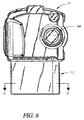
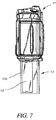
- the overall structure of the present invention will briefly be reviewed with respect to FIGS. 6 and 7.
- the present invention uses an insertable cartridge 10 which is inserted into a digital camera 11.
- the digital camera 11 includes an ink jet printer 13. Further features of the digital camera 11 and ink jet printer 13 will be discussed later.
- FIG. 1 a perspective view of a cartridge 10 is shown, having a housing 9 provided with five ink reservoirs 38.
- the housing 9 is provided with a removable cartridge seal 16 which protects identifying contacts 18, 19, and 20, receivers 30 and ink ports 40 prior to use of the cartridge 10.
- Cartridge seal 16 can be of a Mylar sheet held in position until use by a conventional, low tack adhesive 22 as cartridge seal 16 is used only as protective dust seal.
- the cartridge seal 16 is removed prior to inserting the cartridge 10 into cartridge opening 10a provided in the digital camera 11 (see FIG. 6).
- the cartridge seal 16 can contain human readable data printed on the outer surface (not shown) indicative of the date of manufacture, expiration date, printer compatibility, and so forth.
- Identifying contacts 18, 19 and 20 can be formed by the application of an encoded and patterned metallized tape. Each identifying contact 18, 19 and 20 may be metallized or not forming a conductive or non-conductive area. These identifying contacts 18, 19 and 20 provide information of features of an inserted cartridge 10 to the ink jet printer 13 in the digital camera 11. These identifying contacts 18, 19 and 20 provide information (as will be discussed with reference to FIG. 5A) in a manner similar to the DX encodement of 35 mm film cassettes. For example see commonly assigned US-A-4,982,209. The identifying contacts 18, 19, and 20 are used by the ink jet printer 13 of the digital camera 11 to sense the data represented by the encoded conductive pattern.
- Such data can represent the manufactured configuration of the cartridge 10 with respect to the preloaded media types such as plain or coated paper, ink color set such as photographic or fluorescent, and media quantity as shown in Table 1 below.
- Logic levels shown in Table 1 describe the identification of the contents of cartridge 10 with respect to the type and quantity of receivers 30 along with the style of ink contained in ink reservoirs 38.
- the amount of ink provided during manufacture to the reservoirs and is determined in accordance with the number of receivers to be printed.
- the identification is accomplished by identifying probe pairs 52, 54 and 56 (see FIG. 5A) contacting identifying contacts 18, 19, and 20 respectively, for the purpose of determining the conductivity of each identifying contact 18, 19, and 20.
- Identifying probe pairs 52, 54 and 56 are electrically controlled by circuitry (not shown) within the cartridge interface and printer actuator electronics block 46.
- a small current will flow across the discrete elements of identifying probe pairs 52, 54, and 56 causing a Low Level Voltage to be sensed by cartridge interface and printer actuator electronics block 46 if the identifying contact was conductive. If current does not flow across the probe pairs, the identifying contact was not conductive and a High Level Voltage is sensed by cartridge interface and printer actuator electronics block 46. The identification information is used by the cartridge interface and printer actuator electronics block 46 to produce a superior resultant printed image.
- alignment features are formed in the housing 9 and shown as insertion slots 24 which are used in the positioning of cartridge 10 into ink jet printer 13.
- Battery contacts 26 are formed in such a manner as to protrude into insertion slots 24 with a shape and spring force so as to provide a further alignment feature of the cartridge 10.
- the battery contacts 26 are formed on either side of a cavity 36 provided in the housing 9 which receives the batteries 34.
- the battery contacts 26 mount the batteries and provide electrical connection to them while also providing alignment features for the insertable cartridge 10.
- the housing 9 with a receiver bay 28 is shown containing a partial view of receivers 30 resting on a spring loaded platen 32 which urges the receivers 30 to the top of the cartridge 10 for access to the ink jet printer 13.
- FIG. 2 is a cross-section of the cartridge 10, there are a plurality of ink reservoirs 38 formed in the housing 9 for receiving different colored inks.
- Providing access to each of the ink reservoirs 38 are ink ports 40.
- a pierceable reservoir seal 12 in the form of a plug is provided covering each of the ink ports 40.
- An O-ring 14 is also provided so that when a cartridge 10 is inserted into the ink jet printer 13 and piercing probes 42 pierce the reservoir seals 12 the O-rings 14 seal the communication between the ink reservoirs 38 and the ink jet printer 13 to prevent ink leakage.
- FIGS. 3 and 4 show four batteries 34 provided in cavity 36. As is also shown, there are four springs 31 which urges a platen 32 that carries the receivers 30 so that the top receiver 30 can be used by the ink jet printer 13.
- an image capture and processing electronics block 44 is shown which is included in the digital camera 11.
- the image capture and processing electronics block 44 will be understood to include all the necessary elements to acquire and store images electronically via an image sensor (not shown) as is found in well known digital camera apparatus such as the aforementioned DC-260 digital camera manufactured by the Eastman Kodak Company.
- the digital camera 11 includes a lens 48 and an image sensor (not shown) both of which are controlled by the image capture and processing electronics block 44 and furthermore capture a digital image.
- the image capture and processing electronics block 44 stores the captured image in a digital format and processes such image for use by the ink jet printer 13 which is shown generally in FIG. 6. Continuing with FIG.
- cartridge 10 is shown inserted into digital camera 11 in the direction of the arrow 10b.
- Battery contact 26 on each side of cartridge 10 makes an electrical connection between the cartridge 10 and the power supply voltages denoted as +Vpb and ⁇ Vpb which are used to supply electrical power to the ink jet printer 13 of the digital camera 11 and the cartridge interface and printer actuator electronics block 46 in the normal mode of operation. In such a manner, the user is always assured that the necessary power to print an image is available each time a cartridge 10 is loaded.
- the battery selectable switch 66 is a common single pole multi-throw switch (one switch terminal currently not assigned) which allows the batteries 34 of the cartridge 10 to be additionally coupled to the image capture and processing electronics block 44. It should be noted that the user may choose to actuate the battery selectable switch 66 at any time to conserve power in the digital camera battery 50. One such relevant time would include the exhaustion of cartridge 10 of receivers 30 where power may still remain in batteries 34. Image data, addressing data, and control data necessary for the printing operation travel between the image capture and processing electronics block 44 and the cartridge interface and printer actuator electronics block 46 along data bus 64.
- FIG. 5B an alternative electrical arrangement is shown where battery monitor circuit 72, powered by the batteries 34 of cartridge 10, monitors the digital camera battery 50.
- Battery monitoring circuit 72 causes indicator 68 to light when it detects a low power state of the digital camera battery 50.
- the circuit details (not shown) of battery monitor circuit 72 can easily be implemented with a simple comparator circuit where the comparison threshold is set by a resistor divider network.
- a second output of the battery monitor circuit 72 is a relay control signal 74 which controls the switching state of a relay 70.
- relay 70 switches the power supplied to the image capture and processing electronics 44 to the batteries 34 of cartridge 10.
- battery selectable switch 66 must be in the "NORMAL" position which is shown schematically as position 3.
- the user may choose to set the battery selectable switch to position 2 which overrides the automatic switching feature and connects only the digital camera battery 50 to image capture and processing electronics 44. Alternatively at any time, the user may choose position 1 of battery selectable switch 66 to override the automatic switching feature and connect only batteries 34 of cartridge 10 to the image capture and processing electronics.
- a busy signal 76 is sent from the cartridge interface and printer actuator electronics 46 to the battery monitoring circuit 72 causing it to suspend the relay control signal 74 until the busy signal 76 is removed.
- the busy signal is present when either the image capture and processing electronics 44 or the cartridge interface and printer actuator electronics 46 is engaged in capturing, processing, storing, transmitting, printing or any other operation where a power interruption would be detrimental to the outcome of the operation.
- piercing probes 42 which pierce the reservoir seals 12 are shown in schematic form.
- the batteries 34 (see FIG. 3) provide power to the cartridge interface and printer actuator electronics block 46.
- a digital camera battery 50 is shown in FIG. 5A which provides power to the digital camera 11 and the image capture and processing electronics block 44 irrespective of whether or not a cartridge 10 has been inserted into the cartridge opening 10a (see FIG. 7) in the ink jet printer 13 of the digital camera 11.
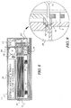
- FIG. 8 is a sectional view of a portion of the taken along lines D-D of the printer of FIG. 6 showing a cross sectional view of a cartridge inserted into an ink jet printer.
- FIG. 9 is an enlarged portion of the sectional view shown in FIG. 8 and shows the reservoir seals 12 and the piercing probes 42 in more detail.
- a feeding roller 58 feeds the top receiver 30 along the path shown by an arrow past the ink jet printer 13.
- a back-up roller 60 presses the receiver sheet against the ink jet printer 13 which prints a line at a time.
- the batteries 34 are provided in cavity 36.
- a tube 62 connects the ink reservoir 38 to the ink jet printer 13 after the reservoir seal 12 has been pierced by a piercing probe 42 which includes a sharp pointed tip.
- the cartridge seal 16 is removed from the cartridge 10.
- the cartridge 10 is inserted into the cartridge opening 10a which has features corresponding to the insertion slot 24 for mounting the cartridge 10.
- Piercing probes 42 pierce the reservoir seals 12 providing communication between the ink reservoirs 38 and the ink jet printer 13.
- Identifying contacts 18, 19 and 20 provide feature information to the cartridge interface and printer actuator electronics block 46 for controlling the operation of the ink jet printer 13 as shown in FIG. 5A.
Landscapes
- Engineering & Computer Science (AREA)
- Multimedia (AREA)
- Signal Processing (AREA)
- Studio Devices (AREA)
- Accessory Devices And Overall Control Thereof (AREA)
- Charge And Discharge Circuits For Batteries Or The Like (AREA)
- Cameras In General (AREA)
Applications Claiming Priority (2)
| Application Number | Priority Date | Filing Date | Title |
|---|---|---|---|
| US198745 | 1998-11-24 | ||
| US09/198,745 US6091909A (en) | 1998-11-24 | 1998-11-24 | Battery control for digital camera and integral printer |
Publications (2)
| Publication Number | Publication Date |
|---|---|
| EP1004927A2 true EP1004927A2 (de) | 2000-05-31 |
| EP1004927A3 EP1004927A3 (de) | 2003-12-10 |
Family
ID=22734637
Family Applications (1)
| Application Number | Title | Priority Date | Filing Date |
|---|---|---|---|
| EP99203812A Withdrawn EP1004927A3 (de) | 1998-11-24 | 1999-11-15 | Batteriemanagement für digitalen Photoapparat und integrierten Drucker |
Country Status (3)
| Country | Link |
|---|---|
| US (1) | US6091909A (de) |
| EP (1) | EP1004927A3 (de) |
| JP (1) | JP2000158752A (de) |
Cited By (1)
| Publication number | Priority date | Publication date | Assignee | Title |
|---|---|---|---|---|
| EP1999806A4 (de) * | 2006-02-09 | 2015-02-18 | Karl F Scheucher | Skalierbares intelligentes stromversorgungssystem und -verfahren |
Families Citing this family (32)
| Publication number | Priority date | Publication date | Assignee | Title |
|---|---|---|---|---|
| AUPQ131399A0 (en) * | 1999-06-30 | 1999-07-22 | Silverbrook Research Pty Ltd | A method and apparatus (NPAGE02) |
| US6786420B1 (en) | 1997-07-15 | 2004-09-07 | Silverbrook Research Pty. Ltd. | Data distribution mechanism in the form of ink dots on cards |
| JPH1132295A (ja) * | 1997-07-09 | 1999-02-02 | Olympus Optical Co Ltd | デジタルカラープリンタ、デジタルカメラ及びそれらを用いたデジタルカラープリントシステム |
| US6618117B2 (en) | 1997-07-12 | 2003-09-09 | Silverbrook Research Pty Ltd | Image sensing apparatus including a microcontroller |
| US20040119829A1 (en) | 1997-07-15 | 2004-06-24 | Silverbrook Research Pty Ltd | Printhead assembly for a print on demand digital camera system |
| US6879341B1 (en) | 1997-07-15 | 2005-04-12 | Silverbrook Research Pty Ltd | Digital camera system containing a VLIW vector processor |
| US6788336B1 (en) | 1997-07-15 | 2004-09-07 | Silverbrook Research Pty Ltd | Digital camera with integral color printer and modular replaceable print roll |
| US6690419B1 (en) | 1997-07-15 | 2004-02-10 | Silverbrook Research Pty Ltd | Utilising eye detection methods for image processing in a digital image camera |
| US7110024B1 (en) | 1997-07-15 | 2006-09-19 | Silverbrook Research Pty Ltd | Digital camera system having motion deblurring means |
| US6624848B1 (en) | 1997-07-15 | 2003-09-23 | Silverbrook Research Pty Ltd | Cascading image modification using multiple digital cameras incorporating image processing |
| AUPP702098A0 (en) | 1998-11-09 | 1998-12-03 | Silverbrook Research Pty Ltd | Image creation method and apparatus (ART73) |
| AUPP701798A0 (en) * | 1998-11-09 | 1998-12-03 | Silverbrook Research Pty Ltd | Image creation method and apparatus (ART75) |
| AUPP702798A0 (en) * | 1998-11-09 | 1998-12-03 | Silverbrook Research Pty Ltd | Image creation method and apparatus (ART70) |
| US7154580B2 (en) * | 1998-11-09 | 2006-12-26 | Silverbrook Research Pty Ltd | Image recordal and generation apparatus |
| JP3357004B2 (ja) * | 1999-02-08 | 2002-12-16 | オリンパス光学工業株式会社 | 電子カメラ |
| AUPQ056099A0 (en) | 1999-05-25 | 1999-06-17 | Silverbrook Research Pty Ltd | A method and apparatus (pprint01) |
| JP2001008138A (ja) * | 1999-06-18 | 2001-01-12 | Minolta Co Ltd | プリンタ一体型デジタルカメラ |
| US20050052661A1 (en) * | 1999-06-30 | 2005-03-10 | Paul Lapstun | Cartridge with identifiers |
| US7831244B2 (en) * | 1999-06-30 | 2010-11-09 | Silverbrook Research Pty Ltd | Retrieving an image via a coded surface |
| JP3802997B2 (ja) * | 1999-07-14 | 2006-08-02 | 富士写真フイルム株式会社 | 電子スチルカメラ |
| US6795114B1 (en) * | 2000-01-31 | 2004-09-21 | Polaroid Corporation | Film unit drive assembly for a detachable electronic photographic printer and camera |
| US7190473B1 (en) | 2000-07-05 | 2007-03-13 | Sherry Anderson Cook | Printer apparatus with integrated graphical user interface and method for using the same |
| JP2002090864A (ja) * | 2000-09-12 | 2002-03-27 | Canon Inc | プリンタ付カメラ |
| JP2002095181A (ja) * | 2000-09-12 | 2002-03-29 | Canon Inc | 複合システム |
| JP2002160387A (ja) * | 2000-09-12 | 2002-06-04 | Canon Inc | メディアパック、プリンタ及びプリンタ付カメラ |
| JP2002232838A (ja) * | 2000-11-28 | 2002-08-16 | Monolith Co Ltd | デジタルカメラ |
| JP4593834B2 (ja) * | 2001-07-02 | 2010-12-08 | 富士フイルム株式会社 | デジタルカメラ及びそのシステム |
| US7123155B2 (en) * | 2002-04-05 | 2006-10-17 | Hewlett-Packard Development Company, L.P. | Operational mode-based battery monitoring for a battery-powered electronic device |
| US7110896B2 (en) * | 2003-04-22 | 2006-09-19 | Hewlett-Packard Development Company, L.P. | System and method for displaying battery status and other parameters of a portable electronic device in a power-off state |
| JP4088603B2 (ja) * | 2004-03-29 | 2008-05-21 | 富士フイルム株式会社 | デバイス組み合わせシステム |
| JP5608695B2 (ja) * | 2012-03-02 | 2014-10-15 | 東芝テック株式会社 | 情報処理装置及び情報処理装置のバッテリ管理方法 |
| US8842298B2 (en) | 2012-05-29 | 2014-09-23 | Eastman Kodak Company | Camera on multifunction printer |
Family Cites Families (10)
| Publication number | Priority date | Publication date | Assignee | Title |
|---|---|---|---|---|
| JPS52123235A (en) * | 1976-04-08 | 1977-10-17 | Canon Inc | Power source change-over system for electric shutter camera |
| US4188105A (en) * | 1978-11-06 | 1980-02-12 | Polaroid Corporation | Battery containing film cassette wherein removal of last sheet insulates contacts |
| JPS59107543U (ja) * | 1983-01-06 | 1984-07-19 | 株式会社ニコン | カメラ用電源装置 |
| US5493409A (en) * | 1990-11-29 | 1996-02-20 | Minolta Camera Kabushiki Kaisha | Still video camera having a printer capable of printing a photographed image in a plurality of printing modes |
| US5257058A (en) * | 1990-11-30 | 1993-10-26 | Canon Kabushiki Kaisha | Interchangeable lens system |
| US5847836A (en) * | 1995-08-29 | 1998-12-08 | Canon Kabushiki Kaisha | Printer-built-in image-sensing apparatus and using strobe-light means electric-consumption control method thereof |
| US5894326A (en) * | 1996-08-26 | 1999-04-13 | Eastman Kodak Company | Electronic camera having a printer |
| US5917548A (en) * | 1996-08-26 | 1999-06-29 | Eastman Kodak Company | Electronic camera having a printer for providing improved hard copy images |
| JPH10170983A (ja) * | 1996-12-16 | 1998-06-26 | Olympus Optical Co Ltd | カメラ |
| US5822637A (en) * | 1997-09-30 | 1998-10-13 | Eastman Kodak Company | Electronic camera and attachable printer |
-
1998
- 1998-11-24 US US09/198,745 patent/US6091909A/en not_active Expired - Lifetime
-
1999
- 1999-11-15 EP EP99203812A patent/EP1004927A3/de not_active Withdrawn
- 1999-11-17 JP JP11326648A patent/JP2000158752A/ja active Pending
Cited By (1)
| Publication number | Priority date | Publication date | Assignee | Title |
|---|---|---|---|---|
| EP1999806A4 (de) * | 2006-02-09 | 2015-02-18 | Karl F Scheucher | Skalierbares intelligentes stromversorgungssystem und -verfahren |
Also Published As
| Publication number | Publication date |
|---|---|
| EP1004927A3 (de) | 2003-12-10 |
| JP2000158752A (ja) | 2000-06-13 |
| US6091909A (en) | 2000-07-18 |
Similar Documents
| Publication | Publication Date | Title |
|---|---|---|
| US6091909A (en) | Battery control for digital camera and integral printer | |
| US6149256A (en) | Insertable cartridge for digital camera with ink jet printer | |
| US6040849A (en) | Insertable thermal printer cartridges for digital camera | |
| JP4722294B2 (ja) | コンパクトプリンタシステム用のインクカートリッジ | |
| US6011937A (en) | Assembly of a printer and its consumption tank for business machine | |
| US20020021320A1 (en) | Printer | |
| US20050041104A1 (en) | Camera and print unit with detachable interface | |
| US20020051136A1 (en) | Printer device | |
| US6909456B1 (en) | Electronic still camera with printer | |
| US7046294B1 (en) | Electronic still camera with printer | |
| JP4040143B2 (ja) | プリンタ及びカートリッジ | |
| JP3357004B2 (ja) | 電子カメラ | |
| JPH10250190A (ja) | 画像処理システム | |
| JPH11155120A (ja) | プリンタと一体結合可能なデジタルカメラシステム | |
| JPH11240231A (ja) | 画像入出力システム、画像入力装置および画像出力装置 | |
| US20020031351A1 (en) | Printing apparatus | |
| JP2000141837A (ja) | デジタルカメラステーション | |
| JPH095850A (ja) | カメラ | |
| KR20010074713A (ko) | 일회용 디지털 카메라 | |
| JP4436550B2 (ja) | プリンタ装置 | |
| JP2002006409A (ja) | プリンタ及びインスタントフイルム | |
| JP2000089338A (ja) | カメラ | |
| JP2000295552A (ja) | 電子カメラ及びその補助バッテリ | |
| JPH1152469A (ja) | 撮影能力表示機能を有したカメラ | |
| JP2000321681A (ja) | 画像形成装置および同装置に収納されるカートリッジ |
Legal Events
| Date | Code | Title | Description |
|---|---|---|---|
| PUAI | Public reference made under article 153(3) epc to a published international application that has entered the european phase |
Free format text: ORIGINAL CODE: 0009012 |
|
| AK | Designated contracting states |
Kind code of ref document: A2 Designated state(s): AT BE CH CY DE DK ES FI FR GB GR IE IT LI LU MC NL PT SE |
|
| AX | Request for extension of the european patent |
Free format text: AL;LT;LV;MK;RO;SI |
|
| PUAL | Search report despatched |
Free format text: ORIGINAL CODE: 0009013 |
|
| AK | Designated contracting states |
Kind code of ref document: A3 Designated state(s): AT BE CH CY DE DK ES FI FR GB GR IE IT LI LU MC NL PT SE |
|
| AX | Request for extension of the european patent |
Extension state: AL LT LV MK RO SI |
|
| RIC1 | Information provided on ipc code assigned before grant |
Ipc: 7B 41J 2/01 B Ipc: 7G 03B 17/48 B Ipc: 7G 03B 17/26 B Ipc: 7G 03B 17/18 B Ipc: 7H 04N 1/00 A |
|
| AKX | Designation fees paid | ||
| REG | Reference to a national code |
Ref country code: DE Ref legal event code: 8566 |
|
| STAA | Information on the status of an ep patent application or granted ep patent |
Free format text: STATUS: THE APPLICATION IS DEEMED TO BE WITHDRAWN |
|
| 18D | Application deemed to be withdrawn |
Effective date: 20040612 |