EP1005042A2 - Méthode et appareil d'enregistrement et de reproduction de signaux vidéo - Google Patents
Méthode et appareil d'enregistrement et de reproduction de signaux vidéo Download PDFInfo
- Publication number
- EP1005042A2 EP1005042A2 EP99309362A EP99309362A EP1005042A2 EP 1005042 A2 EP1005042 A2 EP 1005042A2 EP 99309362 A EP99309362 A EP 99309362A EP 99309362 A EP99309362 A EP 99309362A EP 1005042 A2 EP1005042 A2 EP 1005042A2
- Authority
- EP
- European Patent Office
- Prior art keywords
- picture
- type
- recording
- pictures
- image
- Prior art date
- Legal status (The legal status is an assumption and is not a legal conclusion. Google has not performed a legal analysis and makes no representation as to the accuracy of the status listed.)
- Withdrawn
Links
Images


Classifications
-
- G—PHYSICS
- G11—INFORMATION STORAGE
- G11B—INFORMATION STORAGE BASED ON RELATIVE MOVEMENT BETWEEN RECORD CARRIER AND TRANSDUCER
- G11B27/00—Editing; Indexing; Addressing; Timing or synchronising; Monitoring; Measuring tape travel
- G11B27/02—Editing, e.g. varying the order of information signals recorded on, or reproduced from, record carriers
- G11B27/031—Electronic editing of digitised analogue information signals, e.g. audio or video signals
- G11B27/036—Insert-editing
-
- G—PHYSICS
- G11—INFORMATION STORAGE
- G11B—INFORMATION STORAGE BASED ON RELATIVE MOVEMENT BETWEEN RECORD CARRIER AND TRANSDUCER
- G11B20/00—Signal processing not specific to the method of recording or reproducing; Circuits therefor
- G11B20/10—Digital recording or reproducing
-
- G—PHYSICS
- G11—INFORMATION STORAGE
- G11B—INFORMATION STORAGE BASED ON RELATIVE MOVEMENT BETWEEN RECORD CARRIER AND TRANSDUCER
- G11B15/00—Driving, starting or stopping record carriers of filamentary or web form; Driving both such record carriers and heads; Guiding such record carriers or containers therefor; Control thereof; Control of operating function
- G11B15/02—Control of operating function, e.g. switching from recording to reproducing
-
- G—PHYSICS
- G11—INFORMATION STORAGE
- G11B—INFORMATION STORAGE BASED ON RELATIVE MOVEMENT BETWEEN RECORD CARRIER AND TRANSDUCER
- G11B15/00—Driving, starting or stopping record carriers of filamentary or web form; Driving both such record carriers and heads; Guiding such record carriers or containers therefor; Control thereof; Control of operating function
- G11B15/18—Driving; Starting; Stopping; Arrangements for control or regulation thereof
- G11B15/1808—Driving of both record carrier and head
- G11B15/1875—Driving of both record carrier and head adaptations for special effects or editing
-
- H—ELECTRICITY
- H04—ELECTRIC COMMUNICATION TECHNIQUE
- H04N—PICTORIAL COMMUNICATION, e.g. TELEVISION
- H04N9/00—Details of colour television systems
- H04N9/79—Processing of colour television signals in connection with recording
- H04N9/80—Transformation of the television signal for recording, e.g. modulation, frequency changing; Inverse transformation for playback
- H04N9/804—Transformation of the television signal for recording, e.g. modulation, frequency changing; Inverse transformation for playback involving pulse code modulation of the colour picture signal components
- H04N9/8042—Transformation of the television signal for recording, e.g. modulation, frequency changing; Inverse transformation for playback involving pulse code modulation of the colour picture signal components involving data reduction
-
- G—PHYSICS
- G11—INFORMATION STORAGE
- G11B—INFORMATION STORAGE BASED ON RELATIVE MOVEMENT BETWEEN RECORD CARRIER AND TRANSDUCER
- G11B27/00—Editing; Indexing; Addressing; Timing or synchronising; Monitoring; Measuring tape travel
- G11B27/02—Editing, e.g. varying the order of information signals recorded on, or reproduced from, record carriers
- G11B27/031—Electronic editing of digitised analogue information signals, e.g. audio or video signals
- G11B27/032—Electronic editing of digitised analogue information signals, e.g. audio or video signals on tapes
-
- G—PHYSICS
- G11—INFORMATION STORAGE
- G11B—INFORMATION STORAGE BASED ON RELATIVE MOVEMENT BETWEEN RECORD CARRIER AND TRANSDUCER
- G11B27/00—Editing; Indexing; Addressing; Timing or synchronising; Monitoring; Measuring tape travel
- G11B27/02—Editing, e.g. varying the order of information signals recorded on, or reproduced from, record carriers
- G11B27/031—Electronic editing of digitised analogue information signals, e.g. audio or video signals
- G11B27/034—Electronic editing of digitised analogue information signals, e.g. audio or video signals on discs
-
- H—ELECTRICITY
- H04—ELECTRIC COMMUNICATION TECHNIQUE
- H04N—PICTORIAL COMMUNICATION, e.g. TELEVISION
- H04N5/00—Details of television systems
- H04N5/76—Television signal recording
- H04N5/765—Interface circuits between an apparatus for recording and another apparatus
- H04N5/77—Interface circuits between an apparatus for recording and another apparatus between a recording apparatus and a television camera
- H04N5/772—Interface circuits between an apparatus for recording and another apparatus between a recording apparatus and a television camera the recording apparatus and the television camera being placed in the same enclosure
Definitions
- the present invention relates to methods and apparatuses for recording and reproducing video signals.
- MPEG video signals are compressed and coded in units of groups, which are referred to as Group of Pictures (GOP).
- Each group of pictures is composed of a plurality of pictures of three different types, I-pictures, P-pictures, and B-pictures.
- I-pictures are closed pictures within a frame or a field, and an I-picture is a single independent picture without reference to other pictures.
- P-pictures obtain predictions from temporally preceding I-or P-pictures
- B-pictures obtain predictions from both the nearest preceding and following I- or P-pictures.
- MPEG video signals are highly efficiently compressed.
- a video signal is converted into an MPEG video signal, i.e., an MPEG bitstream
- the temporal order may be reversed within a single GOP.
- an editing operation for example, an image-splicing operation, half way through a single GOP
- the order of pictures may be reversed if the pictures are simply spliced, and the spliced portions are not decoded correctly, which may result in the disturbance of the image and the generation of noise.
- GOPs are generally used as units to perform such an operation.
- a video-signal recording and reproducing apparatus for recording a video signal encoded by an MPEG method on a recording medium and for reproducing the MPEG-encoded video signal from the recording medium.
- the improvement includes that an image-splicing operation is performed in a period at which one of an I-type picture or a P-type picture appears.
- Embodiments of the invention relate to a video-signal recording and reproducing apparatus for recording/reproducing Moving Picture Experts Group (MPEG) video signals and also for performing an editing operation, for example, an image-splicing operation.
- Embodiments of the invention also pertain to a video-signal recording and reproducing method for use in the above type of apparatus.
- MPEG Moving Picture Experts Group
- Embodiments of the present invention can provide a simple video-picture recording and reproducing apparatus for recording and reproducing MPEG video signals on and from recording media, in which an image-splicing operation can be started from a picture positioned midway within one GOP so as to achieve smooth unbroken pictures.
- a video-signal recording and reproducing method for use in a video-signal recording and reproducing apparatus for recording a video signal encoded by an MPEG method on a recording medium and for reproducing the MPEG-encoded video signal from the recording medium.
- the improvement includes that an image-splicing operation is performed in a period at which one of an I-type picture or a P-type picture appears.
- the image-splicing operation can be performed from a picture midway in one GOP.
- smooth unbroken pictures or at least improved pictures are implemented.
- recording in performing the image-splicing operation, recording may be started from an I-type picture, and the I-type picture and any B-type picture encoded with backward reference to the I-type picture may be recorded.
- the designated I-type picture and all B-type pictures encoded with backward reference to the I-type picture may be retained in the recording medium.
- the designated P-type picture and all B-type pictures encoded with backward reference to the P-type picture may be retained in the recording medium.
- a B-type picture When a B-type picture is designated as a final picture to be retained selected from the pictures recorded on the recording medium, the designated B-type picture and all B-type pictures continuous from the designated B-type picture may be retained in the recording medium. Thereafter, an image to be spliced may be recorded.
- the designated I-type picture and all B-type pictures encoded with backward reference to the I-type picture may be recorded.
- a P-type picture is designated as a final picture of the base image
- the designated P-type picture and all B-type pictures encoded with backward reference to the P-type picture may be recorded.
- a B-type picture is designated as a final picture of the base image
- the designated B-type picture and all B-type pictures continuous from the designated B-type picture may be recorded. Thereafter, a recording operation may be suspended.
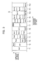
- I-pictures, P-pictures, and B-pictures are indicated by I, P, and B, respectively.
- the symbols a and b in parentheses preceded by I, P, and B represent titles of continuous pictures.
- the numbers after a and b designate picture numbers, which indicate the order before the pictures are MPEG-encoded. That is, the pictures are to be displayed on the screen in ascending numerical order. One picture corresponds to one frame.
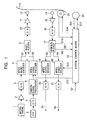
- Fig. 1 is a block diagram illustrating a video-signal recording and reproducing apparatus for recording a picture recorded with a camera as an MPEG video signal on tape and for reproducing it from the tape.
- the recording system of the apparatus is as follows. An audio signal obtained by converting a sound pressure into an analog sound signal by a microphone 1 is amplified by a microphone amplifier 2, and is converted into digital data by an analog-to-digital (A/D) converter 3. Subsequently, the digital data is converted into an MPEG audio bitstream S1 by an MPEG audio encoder 4 and is then input into a multiplexer 5.
- A/D analog-to-digital
- a camera image signal is photoelectrically converted by a charge-coupled device (CCD) 6 and is converted into digital data by an analog-to-digital (A/D) converter 7. Subsequently, the digital data is processed by a camera signal processor 8 and is then converted into an MPEG video bitstream S2 by an MPEG video encoder 9. The MPEG video bitstream S2 is then input into the multiplexer 5.
- CCD charge-coupled device
- A/D analog-to-digital
- the multiplexer 5 multiplexes the input MPEG audio bitstream S1 and the input MPEG video bitstream S2.
- the multiplexed bitstream is converted into an analog signal by a D/A converter 10 and is then amplified by a recording amplifier 11.
- the MPEG audio/video data is recorded on tape 13 via a recording head 12.
- the reproduction system of the apparatus is as follows.
- the MPEG audio/video data recorded on the tape 13 is extracted by a reproduction head 14 and is amplified by a reproduction amplifier 15.
- the resulting reproduced RF signal is further converted into digital data by an A/D converter 16.
- the digital data is separated into an MPEG audio bitstream S3 and an MPEG video bitstream S4 by a demultiplexer 17.
- the MPEG audio bitstream S3 is decoded by an MPEG audio decoder 18 into the digital audio signal and is converted into an analog audio signal S5 by a D/A converter 19 and is then output.
- the MPEG video bitstream S4 is decoded by an MPEG video decoder 20 into the digital video signal and is converted into an analog video signal S6 by a D/A converter 21.
- a system control block 22 is now discussed in detail. The following types of information are input into the system control block 22:
- the state of the apparatus is changed to, for example, a normal reproduction mode, a normal recording mode, a reproduction-suspending mode, or a recording-suspending mode.
- the system control block 22 controls the capstan motor 23 in accordance with the capstan-motor control information S14 based on the capstan-motor rotation information S10, and controls the drum motor 24 in accordance with the drum-motor control information S15 based on the drum-motor rotation information S11.
- the drum-motor rotation information S11 includes rotational speed and rotational phase information of the drum motor 24.
- the system control block 22 transmits the output-picture control information S12 to the MPEG video decoder 20, based on the track number S8 which is currently being reproduced from the tape 13 and the picture type and picture number S9 of the picture contained in the above-mentioned track, both information S8 and S9 being detected by the demultiplexer 17. Also, the system control block 22 transmits the picture-type control information S13 to the MPEG video encoder 9
- Fig. 2 A description is given below with reference to Fig. 2 of the temporal relationship between, for example, a National Television System Committee (NTSC) image before being MPEG-encoded by the MPEG video encoder 9 and an MPEG video bitstream after being MPEG-encoded. It is now assumed that the number of pictures to be contained in a GOP is nine and an I-type picture or a P-type picture appears every three frames.
- NTSC National Television System Committee
- a picture as a B-type picture Before encoding a picture as a B-type picture, as shown in Fig. 2, it is necessary to encode a picture as an I-type picture to be displayed temporally later than the B-type picture. As a result, the order of the encoded data sequence is different from that of displayed pictures. For example, in encoding a picture a0 as a B-type picture, a picture a2, which is temporally later than the picture a0 by two pictures, is first encoded as an I-type picture.
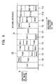
- Fig. 3 illustrates an example of data arrangement in relation to tracks after the MPEG-encoded picture data is recorded on the tape 13 by a helical-scanning method.
- tracks are slantingly arranged, but are indicated at right angles for simple representation.
- the thick lines shown in Fig. 3 designate the border of the pictures.
- the picture I(a2) is partially recorded on the first track T1
- the remaining portion of the picture I(a2) and part of the picture B(a0) are recorded on the track T2
- the remaining portion of the picture B(a0), the picture B(a1), and the picture P(a5) are recorded on the track T3.
- the data length varies among the individual pictures, which is one of the characteristics of MPEG encoding.
- the MPEG bitstream is directly recorded on the tape 13 in the order of I(a2), B(a0), and B(a1). Accordingly, the order of the recorded bitstream, as well as the encoded data sequence, is different from that of the original pictures.
- the system control block 22 starts reproducing pictures from the tape 13, and then temporarily suspends the reproducing operation at the position of the first picture on which another picture is to be superimposed, thereby designating the editing point. Subsequently, the system control block 22 sets the recording and reproducing apparatus in the recording-suspending mode, and then changes the state of the apparatus into the recording mode from the picture at which recording is started by referring to the picture to be input.
- Fig. 4 illustrates how the reproduced pictures are viewed when the image b is superimposed on the image a after the picture I(a11), and Fig. 5 illustrates the data arrangement on the tape 13 after the image b is superimposed.
- the final picture of the image a which should be retained is I(all), in which case, I(all) and all the B-type pictures which refer to this I-picture are retained, and then, recording of the image b is started.
- the reason is as follows. In the display order, the picture I(a11) is located after the pictures B(a9) and B(a10). On the tape 13, however, the picture I(a11) is recorded before the pictures B(a9) and B(a10), as illustrated in Fig. 5. Accordingly, all the data of I(a11), B(a9), and B(a10) are retained, after which the image b is recorded starting from the picture I(b12).
- the recording of pictures of the image b is started from the track T9 in the order of I(b12), P(b15), and B(b13). B(b10) and B(b11) are not recorded since they are not necessary.
- the picture P(a14), which remains in the track T8, is unnecessary, and thus, I(b12) may be recorded from P(a14).
- the overall reproduced pictures are viewed in the order of B(a10), I(a11), I(b12), B(b13), and B(b14), as shown in Fig. 4, thereby achieving smooth unbroken pictures.
- the spliced portion is between I(a11) and I(b12), and the editing precision is ⁇ 0 frames.
- Fig. 6 illustrates how the reproduced pictures are viewed when the image b is superimposed starting from the picture I(b6) after the picture P(a5)
- Fig. 7 illustrates the data arrangement on the tape 13 after the image b is superimposed.
- the final picture of the image a which should be retained is P(a5), in which case, P(a5) and all the B-type pictures which refer to this P-type picture are retained, and then, recording of the image b is started.
- the reason is as follows. In the display order, the picture P(a5) is located after the pictures B(a3) and B(a4). On the tape 13, however, the picture P(a5) is recorded before the pictures B(a3) and B(a4), as illustrated in Fig. 7. Accordingly, all the data of P(a5), B(a3), and B(a4) are retained, after which the image b is recorded starting from the picture I(b6).
- the recording of pictures of the image b is started from the track T5 in the order of I(b6), P(b9), and B(b7).
- the picture P(a8), which remains in the track T4, is unnecessary, and thus, I(b6) may be recorded from P(a8).
- the overall reproduced pictures are observed in the order of B(a4), P(a5), I(b6), B(b7), and B(b8), as illustrated in Fig. 6, thereby achieving smooth unbroken pictures.
- the spliced portion is between P(a5) and I(b6), and the editing precision is ⁇ 0 frames.
- Fig. 8 illustrates how the reproduced pictures are viewed when the image b is superimposed after the picture B(a6)
- Fig. 9 illustrates the data arrangement on the tape 13 after the image b is recorded.
- the final picture of the base image a which should be retained is B(a6), in which case, B(a6) and all the B-type pictures continuous from B(a6) are retained, and then, recording of the image b is started. This is because B(a6) cannot be completely reproduced without P(a8), and the resulting image including P(a8) becomes imperfect without B(a7).
- the recording of pictures of the image b is started from the track T7 in the order of I(b11), B(b9), and B(b10).
- the picture I(a11), which remains in the track T6, is unnecessary, and thus, I(b11) may be recorded from I(a11).
- the reproduced pictures are observed in the order of B(a7), P(a8), B(b9), B(b10), and I(b11), as shown in Fig. 8.
- the spliced portion is between P(a8) and B(b9), and the editing precision is +2 frames.
- the symbol + indicates the direction in which reproduction is delayed behind the editing point.
- Fig. 10 illustrates how the reproduced pictures are viewed when the image b is superimposed after the picture B(a7)
- Fig. 11 illustrates the data arrangement on the tape 13 after the image b is recorded.
- the final picture of the image a which should be retained is B(a7), in which case, B(a7) and all the B-type pictures continuous from B(a7) are retained, and then, recording of the image b is started.
- the recording of pictures of the image b is started from the track T7 in the order of I(b11), B(b9), and B(b10), resulting in the same data arrangement as that in Fig. 9.
- the picture I(a11), which remains in the track T6, is unnecessary, and thus, I(b11) may be recorded from I(a11).
- the reproduced pictures are observed in the order of B(a7), P(a8), B(b9), B(b10), and I(b11), as shown in Fig. 10.
- the spliced portion is between P(a8) and B(b9), and the editing precision is +1 frame.
- the symbol + indicates the direction in which reproduction is delayed behind the editing point.
- recording is basically started from an I-type picture, and any B-type pictures encoded with reference to this I-type picture are retained, thereby achieving unbroken continuous pictures.
- the splicing operation is performed in the interval at which an I- or P-type picture appears, generally, three frames.
- the state of the recording and reproducing apparatus is changed from the recording mode to the recording-suspending mode, and back to the recording mode. This example is stated below with reference to Figs. 12 through 14.
- Fig. 12 illustrates how the reproduced pictures are viewed when an image-splicing operation is performed by changing the state of the apparatus from the recording mode to the recording-suspending mode, and back to the recording mode.
- Fig. 13 illustrates the data arrangement on the tape 13 when the state of the recording and reproducing apparatus is changed from the recording mode to the recording-suspending mode.
- Fig. 14 illustrates the data arrangement on the tape 13 when different images are spliced by changing the state of the recording and reproducing apparatus from the recording mode to the recording-suspending mode, and back to the recording mode.
- the control operation executed by the system control block 22 is roughly the same as that performed when the editing point is designated after suspending the reproducing operation, and then, another image is superimposed on the base image, as previously discussed. In this operation, however, the position of the editing point is automatically specified when the apparatus changes from the recording mode to the recording-suspending mode.
- the apparatus When the key input information S7, indicating the change of the state from the recording mode to the recording-suspending mode, designates the picture B(a6) shown in Fig. 12, the apparatus will enter the recording-suspending mode after the following two pictures are recorded.
- the reason is as follows. Since B(a6) has been encoded with reference to the following P(a8), P(a8) is essential to reproduce a perfect image. Accordingly, pictures up to P(a8), which is positioned after B(a6) by two pictures, are recorded.
- recording is suspended after recording B(a6) and B(a7), as illustrated in Fig. 13, i.e., pictures are recorded up to the track T6.
- the first part of I(a11), which is unnecessary, is recorded, in which invalid data may be recorded, or information indicating the presence of invalid data may be recorded.
- the image b is recorded starting from the picture B(b9).
- the first two pictures are B-type pictures, which refer to the subsequent I-type picture, and then, the I-type picture follows.
- the recording of the image b is started from the track T7 in the order of I(b11), B(b9), and B(b10).
- the reproduced pictures are observed, as illustrated in Fig. 12, in the order of B(a7), P(a8), B(b9), B(b10), and I(b11).
- the spliced portion is between P(a8) and B(b9), and the editing precision is ⁇ 0 frames.
- a deviation of the actual picture from the target picture to be recorded caused by the key input timing is one of ⁇ 0 frames, +1 frame, and +2 frames, as in the case of the deviation generated when an image-splicing operation is conducted by designating the editing point after suspending the reproducing operation.
- the final picture of the base image is a B-type picture
- the B-type picture and all the B-type pictures continuous from the above B-type picture are recorded, thereby completing the recording of the base image.
- the I-type picture and all the B-type pictures which have been encoded with reference to this I-type picture are recorded, since in the display order the B-type pictures are positioned before the I-type picture. For example, if I(a11) is designated, B(a9) and B(a10), which have been encoded with reference to I(a11), are also recorded.
- the final picture of the base image is a P-type picture
- the P-type picture and all the B-type pictures which have been encoded with reference to this P-type picture are recorded, since in the display order the B-type pictures are positioned before the P-type picture. For example, if P(a8) is designated, B(a6) and B(a7), which have been encoded with reference to P(a8), are also recorded.
- the aforementioned recording and reproducing method is used in the recording and reproducing apparatus for recording and reproducing data on and from tape.
- the recording and reproducing method may be used in a recording and reproducing apparatus for recording and reproducing data on and from disk-type recording media.
- tracks are merely substituted with sectors, since one track of tape recorded by helical scanning is equivalent to one sector or one circumference of the disk.
- the video-signal recording and reproducing apparatus of the present invention offers the following advantages.
- the deviation of the position of another image to be superimposed on the base image at which recording is actually started from the target position can be reduced to less than the interval at which an I- or P-type picture appears on the tape, considering when the resulting image is viewed on the display screen. For example, if an I- or P-type picture appears at the interval of three frames, the above-described deviation can be limited to 0, +1, or +2 frames. This also means that the editing precision can be 0, +1, or +2 frames.
- the deviation of the target picture from the final picture of the base image which is actually recorded can be minimized to less than the interval at which an MPEG-encoded I- or P-type picture appears, considering when the resulting image is viewed on the display screen. For example, if an I- or P-type picture appears at the interval of three frames, the above-described deviation can be restricted to 0, +1, or +2 frames.
Landscapes
- Engineering & Computer Science (AREA)
- Signal Processing (AREA)
- Multimedia (AREA)
- Television Signal Processing For Recording (AREA)
- Management Or Editing Of Information On Record Carriers (AREA)
Applications Claiming Priority (2)
| Application Number | Priority Date | Filing Date | Title |
|---|---|---|---|
| JP33628298 | 1998-11-26 | ||
| JP10336282A JP2000165803A (ja) | 1998-11-26 | 1998-11-26 | 映像信号記録再生装置 |
Publications (2)
| Publication Number | Publication Date |
|---|---|
| EP1005042A2 true EP1005042A2 (fr) | 2000-05-31 |
| EP1005042A3 EP1005042A3 (fr) | 2002-06-12 |
Family
ID=18297507
Family Applications (1)
| Application Number | Title | Priority Date | Filing Date |
|---|---|---|---|
| EP99309362A Withdrawn EP1005042A3 (fr) | 1998-11-26 | 1999-11-24 | Méthode et appareil d'enregistrement et de reproduction de signaux vidéo |
Country Status (4)
| Country | Link |
|---|---|
| EP (1) | EP1005042A3 (fr) |
| JP (1) | JP2000165803A (fr) |
| KR (1) | KR100666287B1 (fr) |
| CN (1) | CN1114211C (fr) |
Cited By (6)
| Publication number | Priority date | Publication date | Assignee | Title |
|---|---|---|---|---|
| WO2001035411A1 (fr) * | 1999-11-10 | 2001-05-17 | Thomson Licensing S.A. | Edition precise d'image sans decodage et recodage de train de bits mpeg pour dvd enregistrable |
| US20090328096A1 (en) * | 2008-06-30 | 2009-12-31 | Rgb Networks, Inc. | Preconditioning ad content for digital program insertion |
| US7693400B2 (en) | 2002-11-22 | 2010-04-06 | Canon Kabushiki Kaisha | Imaging apparatus, recording apparatus and recording method |
| US7986865B2 (en) | 2004-11-05 | 2011-07-26 | Sony Corporation | Imaging device and recording control method |
| EP2688071A1 (fr) * | 2004-03-10 | 2014-01-22 | Core Wireless Licensing S.a.r.l. | Procédé et dispositif d'édition de vidéo de domaine compressé |
| CN104243920A (zh) * | 2014-09-04 | 2014-12-24 | 浙江宇视科技有限公司 | 一种基于基本流视频数据封装的图像拼接方法及装置 |
Families Citing this family (2)
| Publication number | Priority date | Publication date | Assignee | Title |
|---|---|---|---|---|
| CN100527835C (zh) * | 2006-05-26 | 2009-08-12 | 威盛电子股份有限公司 | 在有限存储器容量内储存对应mpeg-4视频信息对象的信息的装置及其方法 |
| JP5241865B2 (ja) * | 2011-01-21 | 2013-07-17 | 日立コンシューマエレクトロニクス株式会社 | ビデオカメラ |
Family Cites Families (7)
| Publication number | Priority date | Publication date | Assignee | Title |
|---|---|---|---|---|
| US5557331A (en) * | 1993-03-11 | 1996-09-17 | Matsushita Electric Industrial Co., Ltd. | Image encoding method, an image encoding circuit, an image encoding apparatus, and an optical disk |
| JPH07212766A (ja) * | 1994-01-18 | 1995-08-11 | Matsushita Electric Ind Co Ltd | 動画像圧縮データ切り換え装置 |
| US5771081A (en) * | 1994-02-28 | 1998-06-23 | Korea Telecommunication Authority | Bit system for transmitting digital video data |
| US5534944A (en) * | 1994-07-15 | 1996-07-09 | Matsushita Electric Corporation Of America | Method of splicing MPEG encoded video |
| GB2294173B (en) * | 1994-10-11 | 1998-12-09 | Mitsubishi Electric Corp | Disk media, and method of and device for recording and playing back information on or from a disk media |
| JPH08214265A (ja) * | 1995-01-31 | 1996-08-20 | Sony Corp | 符号化データの再生方法および再生装置 |
| US5774593A (en) * | 1995-07-24 | 1998-06-30 | University Of Washington | Automatic scene decomposition and optimization of MPEG compressed video |
-
1998
- 1998-11-26 JP JP10336282A patent/JP2000165803A/ja active Pending
-
1999
- 1999-11-24 EP EP99309362A patent/EP1005042A3/fr not_active Withdrawn
- 1999-11-26 CN CN99125804A patent/CN1114211C/zh not_active Expired - Fee Related
- 1999-11-26 KR KR1019990052911A patent/KR100666287B1/ko not_active Expired - Fee Related
Cited By (11)
| Publication number | Priority date | Publication date | Assignee | Title |
|---|---|---|---|---|
| WO2001035411A1 (fr) * | 1999-11-10 | 2001-05-17 | Thomson Licensing S.A. | Edition precise d'image sans decodage et recodage de train de bits mpeg pour dvd enregistrable |
| US6707778B1 (en) | 1999-11-10 | 2004-03-16 | Thomson Licensing S.A. | Edit to picture without decoding and re-encoding of MPEG bit stream for recordable DVD |
| KR100745522B1 (ko) * | 1999-11-10 | 2007-08-03 | 톰슨 라이센싱 | 리코드 가능한 dvd에 대한 mpeg 비트 스트림의디코딩 및 재인코딩 없는 화상의 정밀 편집 |
| US7693400B2 (en) | 2002-11-22 | 2010-04-06 | Canon Kabushiki Kaisha | Imaging apparatus, recording apparatus and recording method |
| US9715898B2 (en) | 2003-12-16 | 2017-07-25 | Core Wireless Licensing S.A.R.L. | Method and device for compressed-domain video editing |
| EP2688071A1 (fr) * | 2004-03-10 | 2014-01-22 | Core Wireless Licensing S.a.r.l. | Procédé et dispositif d'édition de vidéo de domaine compressé |
| US7986865B2 (en) | 2004-11-05 | 2011-07-26 | Sony Corporation | Imaging device and recording control method |
| US20090328096A1 (en) * | 2008-06-30 | 2009-12-31 | Rgb Networks, Inc. | Preconditioning ad content for digital program insertion |
| US8904426B2 (en) * | 2008-06-30 | 2014-12-02 | Rgb Networks, Inc. | Preconditioning ad content for digital program insertion |
| CN104243920A (zh) * | 2014-09-04 | 2014-12-24 | 浙江宇视科技有限公司 | 一种基于基本流视频数据封装的图像拼接方法及装置 |
| CN104243920B (zh) * | 2014-09-04 | 2017-09-26 | 浙江宇视科技有限公司 | 一种基于基本流视频数据封装的图像拼接方法及装置 |
Also Published As
| Publication number | Publication date |
|---|---|
| KR100666287B1 (ko) | 2007-01-11 |
| EP1005042A3 (fr) | 2002-06-12 |
| JP2000165803A (ja) | 2000-06-16 |
| CN1114211C (zh) | 2003-07-09 |
| CN1255706A (zh) | 2000-06-07 |
| KR20000035719A (ko) | 2000-06-26 |
Similar Documents
| Publication | Publication Date | Title |
|---|---|---|
| EP1230795B1 (fr) | Elimination d'artefacts de format d'image dans des modes exploration mpeg | |
| JP3701051B2 (ja) | 情報記録装置及び情報再生装置 | |
| JP4442929B2 (ja) | ビデオ情報送信方法、情報坦体、ビデオ情報を受信するための装置及びビデオ情報を送信するための装置 | |
| JPH08168042A (ja) | データ復号化装置およびデータ復号化方法 | |
| JP3552506B2 (ja) | 再生方法及び再生装置 | |
| CN1177431A (zh) | 包括多数据流配置控制转换的便携式动态画面录制设备 | |
| JP2003514419A (ja) | 書き換え可能なdvd向けの、mpegビットストリームの復号化及び再符号化することのない画像の編集 | |
| EP1005042A2 (fr) | Méthode et appareil d'enregistrement et de reproduction de signaux vidéo | |
| US6707984B2 (en) | Changing a playback speed for video presentation recorded in a modified film format | |
| JPH11273258A (ja) | 情報再生装置 | |
| EP0848556A1 (fr) | Méthode et dispositif de décodage et reproduction de signaux vidéo et de parole numériques en continu | |
| US7058280B2 (en) | Reproducing apparatus having high-speed reproducing function | |
| US6292219B1 (en) | Motion processing system using an effects-enhanced motion storage medium | |
| JP3925487B2 (ja) | 撮像装置と撮像方法 | |
| JP3394102B2 (ja) | 光ディスクの再生方法及び再生装置 | |
| JPH10276395A (ja) | 画像処理装置および画像処理方法、並びに記録媒体 | |
| JP3566216B2 (ja) | デジタル音声映像情報の記録装置 | |
| JP4120056B2 (ja) | 再生装置及び再生方法 | |
| US7203012B2 (en) | Signal processing apparatus | |
| US5892883A (en) | Recording of a data reduced digital video signal in slant tracks on a record carrier | |
| JPH08130712A (ja) | データ編集方法及び編集装置 | |
| KR100266371B1 (ko) | 고속재생방법및그데이터구조 | |
| JP2005286829A (ja) | 映像信号記録再生システム | |
| JP4164295B2 (ja) | 情報記録装置及び情報記録方法、情報処理装置及び情報処理方法並びに情報再生装置及び情報再生方法 | |
| JP2004193767A (ja) | ディジタル記録テープの調相再生方法 |
Legal Events
| Date | Code | Title | Description |
|---|---|---|---|
| PUAI | Public reference made under article 153(3) epc to a published international application that has entered the european phase |
Free format text: ORIGINAL CODE: 0009012 |
|
| AK | Designated contracting states |
Kind code of ref document: A2 Designated state(s): AT BE CH CY DE DK ES FI FR GB GR IE IT LI LU MC NL PT SE |
|
| AX | Request for extension of the european patent |
Free format text: AL;LT;LV;MK;RO;SI |
|
| PUAL | Search report despatched |
Free format text: ORIGINAL CODE: 0009013 |
|
| AK | Designated contracting states |
Kind code of ref document: A3 Designated state(s): AT BE CH CY DE DK ES FI FR GB GR IE IT LI LU MC NL PT SE |
|
| AX | Request for extension of the european patent |
Free format text: AL;LT;LV;MK;RO;SI |
|
| 17P | Request for examination filed |
Effective date: 20021128 |
|
| AKX | Designation fees paid |
Designated state(s): DE FR GB |
|
| 17Q | First examination report despatched |
Effective date: 20030404 |
|
| STAA | Information on the status of an ep patent application or granted ep patent |
Free format text: STATUS: THE APPLICATION IS DEEMED TO BE WITHDRAWN |
|
| 18D | Application deemed to be withdrawn |
Effective date: 20030815 |