EP1005117A1 - Source de lumière laser accordable à cavité externe - Google Patents
Source de lumière laser accordable à cavité externe Download PDFInfo
- Publication number
- EP1005117A1 EP1005117A1 EP99123033A EP99123033A EP1005117A1 EP 1005117 A1 EP1005117 A1 EP 1005117A1 EP 99123033 A EP99123033 A EP 99123033A EP 99123033 A EP99123033 A EP 99123033A EP 1005117 A1 EP1005117 A1 EP 1005117A1
- Authority
- EP
- European Patent Office
- Prior art keywords
- mirror
- light
- semiconductor laser
- diffraction grating
- cavity type
- Prior art date
- Legal status (The legal status is an assumption and is not a legal conclusion. Google has not performed a legal analysis and makes no representation as to the accuracy of the status listed.)
- Granted
Links
- 239000004065 semiconductor Substances 0.000 title claims abstract description 39
- 230000001154 acute effect Effects 0.000 claims abstract description 12
- 230000003287 optical effect Effects 0.000 claims description 13
- 238000010408 sweeping Methods 0.000 description 7
- 230000000694 effects Effects 0.000 description 5
- 230000010355 oscillation Effects 0.000 description 5
- 238000010586 diagram Methods 0.000 description 4
- 230000002265 prevention Effects 0.000 description 2
- 230000001427 coherent effect Effects 0.000 description 1
- 238000005516 engineering process Methods 0.000 description 1
- 238000005259 measurement Methods 0.000 description 1
- 239000013307 optical fiber Substances 0.000 description 1
- 238000004904 shortening Methods 0.000 description 1
Images
Classifications
-
- H—ELECTRICITY
- H01—ELECTRIC ELEMENTS
- H01S—DEVICES USING THE PROCESS OF LIGHT AMPLIFICATION BY STIMULATED EMISSION OF RADIATION [LASER] TO AMPLIFY OR GENERATE LIGHT; DEVICES USING STIMULATED EMISSION OF ELECTROMAGNETIC RADIATION IN WAVE RANGES OTHER THAN OPTICAL
- H01S5/00—Semiconductor lasers
- H01S5/10—Construction or shape of the optical resonator, e.g. extended or external cavity, coupled cavities, bent-guide, varying width, thickness or composition of the active region
- H01S5/14—External cavity lasers
- H01S5/141—External cavity lasers using a wavelength selective device, e.g. a grating or etalon
-
- H—ELECTRICITY
- H01—ELECTRIC ELEMENTS
- H01S—DEVICES USING THE PROCESS OF LIGHT AMPLIFICATION BY STIMULATED EMISSION OF RADIATION [LASER] TO AMPLIFY OR GENERATE LIGHT; DEVICES USING STIMULATED EMISSION OF ELECTROMAGNETIC RADIATION IN WAVE RANGES OTHER THAN OPTICAL
- H01S3/00—Lasers, i.e. devices using stimulated emission of electromagnetic radiation in the infrared, visible or ultraviolet wave range
- H01S3/05—Construction or shape of optical resonators; Accommodation of active medium therein; Shape of active medium
- H01S3/08—Construction or shape of optical resonators or components thereof
- H01S3/081—Construction or shape of optical resonators or components thereof comprising three or more reflectors
- H01S3/0811—Construction or shape of optical resonators or components thereof comprising three or more reflectors incorporating a dispersive element, e.g. a prism for wavelength selection
- H01S3/0812—Construction or shape of optical resonators or components thereof comprising three or more reflectors incorporating a dispersive element, e.g. a prism for wavelength selection using a diffraction grating
-
- H—ELECTRICITY
- H01—ELECTRIC ELEMENTS
- H01S—DEVICES USING THE PROCESS OF LIGHT AMPLIFICATION BY STIMULATED EMISSION OF RADIATION [LASER] TO AMPLIFY OR GENERATE LIGHT; DEVICES USING STIMULATED EMISSION OF ELECTROMAGNETIC RADIATION IN WAVE RANGES OTHER THAN OPTICAL
- H01S5/00—Semiconductor lasers
- H01S5/10—Construction or shape of the optical resonator, e.g. extended or external cavity, coupled cavities, bent-guide, varying width, thickness or composition of the active region
- H01S5/14—External cavity lasers
- H01S5/141—External cavity lasers using a wavelength selective device, e.g. a grating or etalon
- H01S5/143—Littman-Metcalf configuration, e.g. laser - grating - mirror
Definitions
- This invention relates to an external cavity type tunable semiconductor laser source used in coherent light communication and measurement technology fields.
- An external cavity type tunable semiconductor laser source generally consists of a semiconductor laser, which will be hereinafter abbreviated to LD, coated on one end face with a reflection prevention film, a lens for converting light from the LD into collimated light, and a wavelength selection element for selecting any desired wavelength.
- a narrow-band-pass filter a narrow-band-pass filter, a diffraction grating, etc., is used as the wavelength selection element.
- a system called Littman-Metcalf configuration is frequently used because it provides high wavelength selectivity.
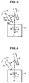
- a mirror 20 is used in addition to an LD 1, a lens 4, and a diffraction grating 2, as shown in FIG. 4.
- emitted light from the LD 1 is converted into collimated light through the lens 4 and is made incident on the diffraction grating 2, through which a wavelength is selected, then the light of the selected wavelength is once applied to the mirror 20 and is reflected thereon, then the reflected light is again made incident on the diffraction grating 2 and is fed back into the LD 1, thereby providing excellent wavelength selectivity.
- the mirror 20 in the Littman-Metcalf configuration, it is necessary to attach the mirror 20 to a position near the LD 1 and the lens 4 because of the characteristic of the diffracted light emission direction of the diffraction grating 2 and to select a wavelength, the mirror 20 needs to be turned so as not to hit a cabinet 10 for housing the LD 1 and the lens 4, thus there has been a tendency to lengthen the external resonator length.
- an external cavity type tunable semiconductor laser source for converting emitted light from a semiconductor laser into collimated light through a lens, making the light incident on a diffraction grating, through which a wavelength is selected, then once applying the light of the selected wavelength to a mirror and reflecting the light thereon, then again making the reflected light incident on the diffraction grating and feeding back the light into the semiconductor light, characterized in that the mirror is formed roughly like a pillar and an angle which a side closest to a cabinet for housing the semiconductor laser and the lens forms with a reflection face coated with a surface reflection film is formed as an acute angle.
- the mirror is formed roughly like a pillar and the angle which the side closest to the cabinet for housing the semiconductor laser and the lens forms with the reflection face coated with a surface reflection film is formed as an acute angle.
- the angle which the side closest to the cabinet for housing the semiconductor laser and the lens forms with the reflection face coated with a surface reflection film is formed as an acute angle.
- the mirror is formed so as to be able to turn.
- the mirror is formed so as to be able to turn, so that wavelength sweeping corresponding to the turning angle of the mirror is enabled.
- an intersection point of an line extended vertically to an optical axis with an optical position of an end face of the semiconductor laser away from the diffraction grating with respect to the diffraction grating as a starting point and an extension of a diffraction face of the diffraction grating is matched with the turning center of the mirror, and
- the intersection point of the line extended vertically to the optical axis with the optical position of the end face of the semiconductor laser away from the diffraction grating with respect to the diffraction grating as the starting point and the extension of the diffraction face of the diffraction grating is matched with the turning center of the mirror, and the mirror is placed so that the extension of the reflection face of the mirror passes through the intersection point, thus occurrence of mode hop can be prevented over a wide range and continuous wavelength sweeping with less variations in light output is enabled.
- the mirror is formed of a triangular prism.
- the mirror is formed of a triangular prism easily molded, so that the cost of the mirror can be reduced.
- the mirror is formed of a parallelogram prism.
- the mirror is formed of a parallelogram prism easily molded so that the cost of the mirror can be reduced.
- FIGS. 1 to 3 there is shown an embodiment of the invention.
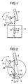
- FIG. 1 is a block diagram to show an example of an external cavity type tunable LD light source incorporating the invention.
- FIG. 2 is a drawing to describe the placement and the operation of a mirror forming a part of the external cavity type tunable LD light source in FIG. 1.
- the external cavity type tunable LD light source of the embodiment is made up of an LD 1 coated on one end face 1a with a reflection prevention film 1A, a diffraction grating 2 as a wavelength selection element, a triangular prism 3 shown as an example of a mirror, a lens 4 for converting light from the LD 1 into collimated light, a cabinet 10 for housing the LD 1 and the lens 4, and the like.
- the triangular prism 3 is formed roughly like a triangle pole and an angle 3c which a side 3b closest to the cabinet 10 forms with a reflection face 3a coated with a surface reflection film is formed as an acute angle.
- an angle 3c which a side 3b closest to the cabinet 10 forms with a reflection face 3a coated with a surface reflection film is formed as an acute angle.
- Diffracted light incident on the diffraction grating 2 and having a wavelength selected therethrough is once vertically incident on the triangular prism 3 and is totally reflected on the reflection face 3a of the triangular prism 3, then is returned to the diffraction grating 2. That is, the wavelength is selected twice through the diffraction grating 2, whereby the wavelength selectivity is enhanced.
- the light whose wavelength is thus selected is gathered through the lens 4 and is fed back into the LD 1. That is, an end face 1b of the LD 1 and the diffraction grating 2 make up an external resonator for laser oscillation.
- the emitted light from the end face 1b of the LD 1 passes through a lens, a light isolator, etc., (not shown) and is gathered, then is taken out as output light through an optical fiber.
- the external cavity type tunable LD light source in FIG. 1 is provided with a turning mechanism (not shown) capable of turning the triangular prism 3 and the triangular prism 3 is turned by the turning mechanism, whereby wavelength sweeping is enabled.
- the turning center of the triangular prism 3 matches an intersection point C of a line L1 extended vertically to the optical axis with an optical position C1 of the end face 1b of the LD 1 with respect to the diffraction grating 2 (position of the end face 1b with respect to the diffraction grating 2 if the length in the optical axis direction of the lens 4 and the LD 1) as the starting point and an extension L2 of a diffraction face of the diffraction grating 2.
- the triangular prism 3 is placed so that an extension L3 of the reflection face 3a of the triangular prism 3 passes through the intersection point C.
- the turning mechanism for turning the triangular prism 3 can be made up of, for example, a sine bar held rotatably with the intersection point C as the axis center and drive means for rotating the sine bar, such as a direct-acting motor.
- the triangular prism 3 is fixedly secured on a bottom face (rear face viewed from FIG. 1) to the tip side of the sine bar to lessen the effect produced by thermal expansion, etc.
- the triangular prism 3 is a pillar-like mirror rather than a flat-panel mirror, thus is fixed to the sine bar in a stable state.
- the mirror is formed of the triangular prism 3 and the angle 3c which the side 3b closest to the cabinet 10 forms with the reflection face 3a coated with the surface reflection film is formed as an acute angle.
- the angle 3c which the side 3b closest to the cabinet 10 forms with the reflection face 3a coated with the surface reflection film is formed as an acute angle.
- intersection point C of the line L1 extended vertically to the optical axis with the optical position C1 of the end face 1b of the LD 1 with respect to the diffraction grating 2 as the starting point and the extension L2 of the diffraction face of the diffraction grating 2 is matched with the turning center of the triangular prism 3, and the triangular prism 3 is placed so that the extension L3 of the reflection face 3a of the triangular prism 3 passes through the intersection point C, thus occurrence of mode hop can be prevented in a wide range and continuous wavelength sweeping with less variations in light output is enabled.
- the external cavity type tunable LD light source adopting such placement can also provide stable laser oscillation.
- the triangular prism 3 is shown as an example, but the scope of the invention is not limited to it. Any mirror may be adopted if it is formed roughly like a pillar, such as a parallelogram prism 13 as shown in FIG. 3, and the angle (here, angle 13C) which the side closest to a cabinet 10 (here, side 13b) forms with the reflection face coated with a surface reflection film (here, reflection face 13a) is formed as an acute angle.
- the placement of the triangular prism 3, the diffraction grating 2, and the LD 1 forming the external cavity type tunable semiconductor laser source is not limited to the placement shown in FIG. 2; for example, it may be general Littman-Metcalf configuration.
- the mirror is formed roughly like a pillar and the angle which the side closest to the cabinet for housing the semiconductor laser and the lens forms with the reflection face coated with a surface reflection film is formed as an acute angle.
- the angle which the side closest to the cabinet for housing the semiconductor laser and the lens forms with the reflection face coated with a surface reflection film is formed as an acute angle.
- the mirror is formed so as to be able to turn, so that wavelength sweeping corresponding to the turning angle of the mirror is enabled.
- the intersection point of the line extended vertically to the optical axis with the optical position of the end face of the semiconductor laser away from the diffraction grating with respect to the diffraction grating as the starting point and the extension of the diffraction face of the diffraction grating is matched with the turning center of the mirror, and the mirror is placed so that the extension of the reflection face of the mirror passes through the intersection point, thus occurrence of mode hop can be prevented over a wide range and continuous wavelength sweeping with less variations in light output is enabled.
- the mirror is formed of a triangular prism easily molded, so that the cost of the mirror can be reduced.
- the mirror is formed of a parallelogram prism easily molded, so that the cost of the mirror can be reduced.
Landscapes
- Physics & Mathematics (AREA)
- Electromagnetism (AREA)
- Optics & Photonics (AREA)
- Engineering & Computer Science (AREA)
- Plasma & Fusion (AREA)
- Condensed Matter Physics & Semiconductors (AREA)
- General Physics & Mathematics (AREA)
- Semiconductor Lasers (AREA)
Applications Claiming Priority (2)
| Application Number | Priority Date | Filing Date | Title |
|---|---|---|---|
| JP33442198 | 1998-11-25 | ||
| JP10334421A JP2000164980A (ja) | 1998-11-25 | 1998-11-25 | 外部共振器型波長可変半導体レーザ光源 |
Publications (2)
| Publication Number | Publication Date |
|---|---|
| EP1005117A1 true EP1005117A1 (fr) | 2000-05-31 |
| EP1005117B1 EP1005117B1 (fr) | 2004-03-24 |
Family
ID=18277195
Family Applications (1)
| Application Number | Title | Priority Date | Filing Date |
|---|---|---|---|
| EP19990123033 Expired - Lifetime EP1005117B1 (fr) | 1998-11-25 | 1999-11-19 | Source de lumière laser accordable à cavité externe |
Country Status (4)
| Country | Link |
|---|---|
| EP (1) | EP1005117B1 (fr) |
| JP (1) | JP2000164980A (fr) |
| CA (1) | CA2290208A1 (fr) |
| DE (1) | DE69915778T2 (fr) |
Cited By (2)
| Publication number | Priority date | Publication date | Assignee | Title |
|---|---|---|---|---|
| CN115066655A (zh) * | 2020-03-19 | 2022-09-16 | 极光先进雷射株式会社 | 窄带化装置和电子器件的制造方法 |
| CN115360586A (zh) * | 2022-05-12 | 2022-11-18 | 浙江法拉第激光科技有限公司 | 基于角锥阵列外腔反射镜的光栅激光器 |
Families Citing this family (5)
| Publication number | Priority date | Publication date | Assignee | Title |
|---|---|---|---|---|
| EP2280260B1 (fr) * | 2003-06-06 | 2017-03-08 | The General Hospital Corporation | Procédé et appareil pour une source de lumière à réglage de longueur d'onde |
| JP2007309881A (ja) * | 2006-05-22 | 2007-11-29 | Fujifilm Corp | 波長掃引光源および光断層画像化装置 |
| KR100945422B1 (ko) | 2008-04-04 | 2010-03-04 | (주)레이저옵텍 | 파장가변 외부공진 레이저 |
| KR101338309B1 (ko) | 2012-03-20 | 2013-12-09 | 연세대학교 산학협력단 | 외부 공진기 레이저 시스템 |
| CN113131340B (zh) * | 2021-04-08 | 2022-07-08 | 中国科学院理化技术研究所 | 一种外腔调制的半导体激光器 |
Citations (3)
| Publication number | Priority date | Publication date | Assignee | Title |
|---|---|---|---|---|
| JPS5871687A (ja) * | 1981-10-23 | 1983-04-28 | Ricoh Co Ltd | 発振波長を安定化した半導体レ−ザ装置 |
| JPH0216782A (ja) * | 1988-07-04 | 1990-01-19 | Toshiba Corp | 狭帯域レーザ装置 |
| DE19544897A1 (de) * | 1995-12-01 | 1997-06-05 | Hannover Laser Zentrum | Abstimmbares Halbleiter-Lasersystem |
-
1998
- 1998-11-25 JP JP10334421A patent/JP2000164980A/ja active Pending
-
1999
- 1999-11-19 EP EP19990123033 patent/EP1005117B1/fr not_active Expired - Lifetime
- 1999-11-19 CA CA 2290208 patent/CA2290208A1/fr not_active Abandoned
- 1999-11-19 DE DE1999615778 patent/DE69915778T2/de not_active Expired - Fee Related
Patent Citations (3)
| Publication number | Priority date | Publication date | Assignee | Title |
|---|---|---|---|---|
| JPS5871687A (ja) * | 1981-10-23 | 1983-04-28 | Ricoh Co Ltd | 発振波長を安定化した半導体レ−ザ装置 |
| JPH0216782A (ja) * | 1988-07-04 | 1990-01-19 | Toshiba Corp | 狭帯域レーザ装置 |
| DE19544897A1 (de) * | 1995-12-01 | 1997-06-05 | Hannover Laser Zentrum | Abstimmbares Halbleiter-Lasersystem |
Non-Patent Citations (3)
| Title |
|---|
| LIU K ET AL: "NOVEL GEOMETRY FOR SINGLE-MODE SCANNING OF TUNABLE LASERS", OPTICS LETTERS,US,OPTICAL SOCIETY OF AMERICA, WASHINGTON, vol. 6, no. 3, 1 March 1981 (1981-03-01), pages 117 - 118, XP000710138, ISSN: 0146-9592 * |
| PATENT ABSTRACTS OF JAPAN vol. 007, no. 166 (E - 188) 21 July 1983 (1983-07-21) * |
| PATENT ABSTRACTS OF JAPAN vol. 014, no. 161 (E - 0909) 28 March 1990 (1990-03-28) * |
Cited By (2)
| Publication number | Priority date | Publication date | Assignee | Title |
|---|---|---|---|---|
| CN115066655A (zh) * | 2020-03-19 | 2022-09-16 | 极光先进雷射株式会社 | 窄带化装置和电子器件的制造方法 |
| CN115360586A (zh) * | 2022-05-12 | 2022-11-18 | 浙江法拉第激光科技有限公司 | 基于角锥阵列外腔反射镜的光栅激光器 |
Also Published As
| Publication number | Publication date |
|---|---|
| EP1005117B1 (fr) | 2004-03-24 |
| DE69915778D1 (de) | 2004-04-29 |
| DE69915778T2 (de) | 2004-08-05 |
| JP2000164980A (ja) | 2000-06-16 |
| CA2290208A1 (fr) | 2000-05-25 |
Similar Documents
| Publication | Publication Date | Title |
|---|---|---|
| US6049554A (en) | External cavity, continuously tunable wavelength source | |
| US5993073A (en) | Semiconductor laser module | |
| US20050105566A1 (en) | Laser diode arrangement with external resonator | |
| JPH11214799A (ja) | 半導体レーザモジュール | |
| EP1139524A2 (fr) | Source lumière laser à cavité externe | |
| JPH11163450A (ja) | 波長可変光源 | |
| US6700904B2 (en) | Light source for an external cavity laser | |
| GB2271463A (en) | Semiconductor laser with external resonant cavity | |
| US6999482B2 (en) | Wavelength tunable laser with diffractive optical element | |
| EP1005117B1 (fr) | Source de lumière laser accordable à cavité externe | |
| EP0911924B1 (fr) | Source de lumière laser à cavité externe | |
| CA2290063C (fr) | Source lumineuse de type a cavite externe | |
| JP3069643B2 (ja) | 波長可変光源 | |
| JPH06140717A (ja) | 外部共振器型半導体レーザ光源 | |
| EP1537637B1 (fr) | Resonateur reglable en longueur d'onde equipe d'un prisme | |
| JPH09129982A (ja) | 外部共振器型ld光源 | |
| JPH1117286A (ja) | 波長可変レーザ装置 | |
| JPH04105382A (ja) | 半導体レーザ装置 | |
| JP3422804B2 (ja) | レーザ発振器のスペクトル線幅制御装置 | |
| JP3138730B2 (ja) | 外部共振器型半導体レーザ | |
| JP2002329925A (ja) | 半導体レーザモジュール | |
| JP2000183453A (ja) | 外部共振器型光源 | |
| JPH0282677A (ja) | 外部共振器付半導体レーザ | |
| JP2002116412A (ja) | 携帯型レーザ装置 |
Legal Events
| Date | Code | Title | Description |
|---|---|---|---|
| PUAI | Public reference made under article 153(3) epc to a published international application that has entered the european phase |
Free format text: ORIGINAL CODE: 0009012 |
|
| AK | Designated contracting states |
Kind code of ref document: A1 Designated state(s): DE FR IT |
|
| AX | Request for extension of the european patent |
Free format text: AL;LT;LV;MK;RO;SI |
|
| 17P | Request for examination filed |
Effective date: 20000706 |
|
| AKX | Designation fees paid |
Free format text: DE FR IT |
|
| GRAP | Despatch of communication of intention to grant a patent |
Free format text: ORIGINAL CODE: EPIDOSNIGR1 |
|
| GRAS | Grant fee paid |
Free format text: ORIGINAL CODE: EPIDOSNIGR3 |
|
| GRAA | (expected) grant |
Free format text: ORIGINAL CODE: 0009210 |
|
| AK | Designated contracting states |
Kind code of ref document: B1 Designated state(s): DE FR IT |
|
| PG25 | Lapsed in a contracting state [announced via postgrant information from national office to epo] |
Ref country code: IT Free format text: LAPSE BECAUSE OF FAILURE TO SUBMIT A TRANSLATION OF THE DESCRIPTION OR TO PAY THE FEE WITHIN THE PRESCRIBED TIME-LIMIT;WARNING: LAPSES OF ITALIAN PATENTS WITH EFFECTIVE DATE BEFORE 2007 MAY HAVE OCCURRED AT ANY TIME BEFORE 2007. THE CORRECT EFFECTIVE DATE MAY BE DIFFERENT FROM THE ONE RECORDED. Effective date: 20040324 Ref country code: FR Free format text: LAPSE BECAUSE OF FAILURE TO SUBMIT A TRANSLATION OF THE DESCRIPTION OR TO PAY THE FEE WITHIN THE PRESCRIBED TIME-LIMIT Effective date: 20040324 |
|
| REF | Corresponds to: |
Ref document number: 69915778 Country of ref document: DE Date of ref document: 20040429 Kind code of ref document: P |
|
| PLBE | No opposition filed within time limit |
Free format text: ORIGINAL CODE: 0009261 |
|
| STAA | Information on the status of an ep patent application or granted ep patent |
Free format text: STATUS: NO OPPOSITION FILED WITHIN TIME LIMIT |
|
| EN | Fr: translation not filed | ||
| 26N | No opposition filed |
Effective date: 20041228 |
|
| PGFP | Annual fee paid to national office [announced via postgrant information from national office to epo] |
Ref country code: DE Payment date: 20051117 Year of fee payment: 7 |
|
| PG25 | Lapsed in a contracting state [announced via postgrant information from national office to epo] |
Ref country code: DE Free format text: LAPSE BECAUSE OF NON-PAYMENT OF DUE FEES Effective date: 20070601 |