EP1005216B1 - Verfahren und Vorrichtung zur Validierung von Konfigurationsdaten für Telekommunikationssysteme - Google Patents
Verfahren und Vorrichtung zur Validierung von Konfigurationsdaten für Telekommunikationssysteme Download PDFInfo
- Publication number
- EP1005216B1 EP1005216B1 EP99440323A EP99440323A EP1005216B1 EP 1005216 B1 EP1005216 B1 EP 1005216B1 EP 99440323 A EP99440323 A EP 99440323A EP 99440323 A EP99440323 A EP 99440323A EP 1005216 B1 EP1005216 B1 EP 1005216B1
- Authority
- EP
- European Patent Office
- Prior art keywords
- validation
- rule set
- configuration data
- module
- validation rule
- Prior art date
- Legal status (The legal status is an assumption and is not a legal conclusion. Google has not performed a legal analysis and makes no representation as to the accuracy of the status listed.)
- Expired - Lifetime
Links
Images


Classifications
-
- H—ELECTRICITY
- H04—ELECTRIC COMMUNICATION TECHNIQUE
- H04L—TRANSMISSION OF DIGITAL INFORMATION, e.g. TELEGRAPHIC COMMUNICATION
- H04L41/00—Arrangements for maintenance, administration or management of data switching networks, e.g. of packet switching networks
- H04L41/08—Configuration management of networks or network elements
- H04L41/0866—Checking the configuration
- H04L41/0869—Validating the configuration within one network element
-
- H—ELECTRICITY
- H04—ELECTRIC COMMUNICATION TECHNIQUE
- H04Q—SELECTING
- H04Q3/00—Selecting arrangements
- H04Q3/42—Circuit arrangements for indirect selecting controlled by common circuits, e.g. register controller, marker
- H04Q3/54—Circuit arrangements for indirect selecting controlled by common circuits, e.g. register controller, marker in which the logic circuitry controlling the exchange is centralised
- H04Q3/545—Circuit arrangements for indirect selecting controlled by common circuits, e.g. register controller, marker in which the logic circuitry controlling the exchange is centralised using a stored program
- H04Q3/54508—Configuration, initialisation
- H04Q3/54533—Configuration data, translation, passwords, databases
-
- H—ELECTRICITY
- H04—ELECTRIC COMMUNICATION TECHNIQUE
- H04Q—SELECTING
- H04Q2213/00—Indexing scheme relating to selecting arrangements in general and for multiplex systems
- H04Q2213/13103—Memory
-
- H—ELECTRICITY
- H04—ELECTRIC COMMUNICATION TECHNIQUE
- H04Q—SELECTING
- H04Q2213/00—Indexing scheme relating to selecting arrangements in general and for multiplex systems
- H04Q2213/13106—Microprocessor, CPU
-
- H—ELECTRICITY
- H04—ELECTRIC COMMUNICATION TECHNIQUE
- H04Q—SELECTING
- H04Q2213/00—Indexing scheme relating to selecting arrangements in general and for multiplex systems
- H04Q2213/13109—Initializing, personal profile
-
- H—ELECTRICITY
- H04—ELECTRIC COMMUNICATION TECHNIQUE
- H04Q—SELECTING
- H04Q2213/00—Indexing scheme relating to selecting arrangements in general and for multiplex systems
- H04Q2213/1334—Configuration within the switch
Definitions
- the present invention relates to a method for validating configuration data as operating parameters of telecommunication systems, as well as a validation module according to the preamble of claim 7 therefor, a server according to the preamble of claim 8 therefor, a control module and a storage means therefor.
- Telecommunication systems such as exchanges, access systems, cross-connects, network management systems, computer networks, etc.
- configuration data can be selected within certain limits to specific requirements, which are determined by the respective field of use.
- a control software contained in a telecommunication system can control the telecommunication system as intended in the respective field of application.
- a modern digital exchange for example, must be specified by appropriate configuration data, among other things, which subscriber lines the exchange has to use, which numbers to each of these are assigned and which telecommunication services are made available to the respective subscriber lines.
- the configuration data of such a local loop must comply with predetermined rules.
- a telephone number of a subscriber line may contain only numerals and no letters and must consist of a predetermined number of digits.
- ISDN telecommunications network Integrated Services Digital Network
- configuration data could be checked by the telecommunication system itself to be configured.
- configuration data for a telecommunication system is usually very large and complicated Conditions must then be sufficient in the telecommunications system, a comprehensive "testing software" required, which would need in the telecommunication system for other purposes urgent used resources, eg storage space. Therefore, such configuration data is created by means of a configuration system suitable for configuration data of a telecommunication system or a type of such a telecommunication system, respectively.
- a typical example of such a configuration system is in the European patent application EP 0 678 817 A1 shown.
- configuration data are acquired by a computer with the aid of a graphical user interface and, after the input with the aid of a program module, subjected to a check of its consistency, that is to say a validation. Only then is the configuration data written to a database and subsequently processed into a state in which it can be loaded into a telecommunications system called a "target system".
- target system a telecommunications system
- Such a "hard” programmed graphical user interface as well as a likewise “hard” programmed associated validation program modules are only optimized and appropriate for the generation of configuration data for a particular destination telecommunication system, so that for each destination telecommunication system or type of such system in each case a specially designed for the respective target telecommunications system configuration system must be created and used.
- the configuration data must meet, eg because a new control software of a telecommunications system Requires configuration data in another form or to a different extent or because in configuration data additionally new data types for configuring new features are included, also for the new configuration data suitable new validation program module must be created or an existing validation program module at least partially reprogrammed and then compiled.
- a new validation program module is time-consuming and only possible with the help of programming tools.
- such reprogramming easily makes errors that must be determined by extensive testing of the new or modified validation program module and then corrected.
- the object of the invention is to validate configuration data of a telecommunication system in an efficient manner according to the validation rules required for the telecommunication system operating in each case with the configuration data.
- the invention is based on the idea of designing a validation module, a program module that can be executed on a computer, in such a way that the validation module has validation rules which are respectively required for the validation of configuration data of a telecommunication system and a validation rule set are determined before the actual validation of the configuration data.
- a validation rule set determined in this way is then read out of a memory by the validation module and checks the configuration data according to the validation rules contained in the validation rule set.
- the validation rules are therefore not contained in the actual validation module, but instead are read in again, depending on the configuration data to be tested, and evaluated by the validation module.
- the validation module reads in control data in which the validation rule set belonging to the configuration data is defined. In a further embodiment of the invention, the validation module determines, based on an identifier which is contained in the configuration data to be checked, which validation rule set is to be used for checking the configuration data. In a variant of the invention, the validation rules of a validation rule set are written in a so-called interpreter language and are interpreted by the validation module when checking the configuration data. However, it is also possible that the validation rules are already written in a language that can be executed by a processor and are incorporated directly into the checking process as so-called functions by the validation module.
- FIG. 1 shows a very schematic example of an arrangement for carrying out the method according to the invention.
- a validation module VM according to the invention is shown, which can be executed as a program module on a computer, eg a personal computer or a workstation, and can validate configuration data, exemplified by configuration data KD, universally for various telecommunication systems.
- An example of a telecommunication system is in the form of a target system TS in FIG. 1 shown.
- the target system TS can be configured with configuration data KD.
- the destination system TS can be, for example, an exchange or a network management system.
- the configuration data KD contain, for example, data about connections that can be switched by the destination system TS or data that defines subscriber lines operated by the destination system TS.
- the target system TS can also be, for example, a telecontrol substation.
- the configuration data KD then contains, for example, data about measured values and commands which the remote control substation is to acquire or output.
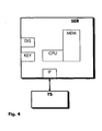
- a computer for executing the validation module VM is in some essential components is in FIG. 4 represented as server SER.
- the server SER contains a control means CPU, for example a processor, for executing machine-readable instructions, eg for executing the validation module VM.
- the server SER has a memory MEM in which the validation module VM can be stored.
- the server SER has as input and output means a keypad KEY and a display device DIS, eg to output data generated by the validation module VM or to send data to the validation module VM.
- the server SER has an interface device IF, via which it outputs data with the FIG. 1 known target system TS can exchange.
- the components of the server SER are defined by in FIG. 4 not shown interconnected connections.
- An operating system such as UNIX or DOS (D isc O perating S ystem), manages the resources of the server SER and controls, among other things, the execution of the validation module VM.
- DOS isc O perating S ystem
- the validation module VM can validate the configuration data KD according to one or more validation rules contained in a validation rule set. Examples of such validation rule sets are in the form of a validation rule set VR1 and a validation rule set VR2 in FIG. 1 shown. The validation rule sets VR1 and VR2 are examples of further, in FIG. 1 not shown validation rule sets and are stored in the memory MEM.
- the configuration data KD are sent from the target system TS to the validation module VM or from an in FIG. 1 not shown program module detected, for example, read by an editor or a graphical user interface or via the interface device IF.
- the configuration data KD are transmitted to the validation module VM, for example in the form of a file which is stored in the memory MEM, or by means of messages which are sent to the validation module VM.
- the process of submitting is in FIG. 1 indicated by an arrow.
- the validation module VM determines according to which validation rules the configuration data KD are to be checked. For this purpose, the validation module VM uses control data VCONF, which specifies in which validation rule set the required validation rules are contained.
- the control data can be stored, for example, in the form of a control table, in each of which an assignment of configuration data to a validation rule set is defined. For example, it may be specified that one particular type of target system requires configuration data to be validated against the validation rule set VR1, while another type of target system requires configuration data that must withstand the validation rule set VR2. In the example off FIG. 1 is defined in the control data VCONF that the configuration data KD are to be checked according to the specifications of the validation rule set VR2.
- the validation module VM reads the validation rule set VR2 from the memory MEM and checks the configuration data KD in accordance with the specifications of the validation rule set VR2.
- the result of the check is reported by the validation module VM with a notification message MSG, for example in the form of an output on the display device DIS or on a printer. With the help of the message MSG, errors that occurred during the check can also be displayed in detail. If the configuration data KD checked by the validation module VM have withstood the check, ie are consistent, the configuration data KD can be loaded, for example, via the interface device IF into the target system TS and adopted by it as an operating parameter.
- the requirements which the configuration data KD have to fulfill for the correct operation of the target system TS have changed, it is sufficient merely to exchange the validation rule set VR2 or to modify it so that the data in the new or the second modified validation rule set VR2 ensure a complete, adapted to the new requirements of the target system TS validation validation.
- the validation module VM itself does not have to be changed. In this way, it is also easily possible to insert further validation rules into a validation rule set or to remove validation rules no longer needed from a validation rule set.
- a new validation rule set can also be added to the validation rule sets VR1 and VR2 at any time, with which the new configuration data can be validated.
- the validation module VM can use this default information to design the notification message MSG.
- default information e.g. Text elements containing content of the notification message MSG
- the validation module VM can use this default information to design the notification message MSG.
- the validation rule sets VR1 or VR2 for each of the validation rules contained therein, which error message is to be displayed by the validation module VM if an error occurs in a check according to the specifications of the respective validation rule.
- this specification information as well as the validation rules can be easily exchanged or modified to meet current requirements.
- a new text added to a validation rule set for an error message will further specify a cause for an error.
- the validation module VM can also determine before the reading of the configuration data KD with which the validation rule sets VR1 or VR2, the configuration data KD are to be checked, for example, if the control data VCONF are given as so-called call parameters the validation module VM already at its start.
- the validation module VM determines on the basis of the configuration data KD which of the validation rule sets VR1 or VR2 is needed for checking the configuration data KD. For this purpose, the validation module VM searches in the configuration data KD for a feature or an identifier that uniquely identifies the configuration data KD. Such an identifier is included in the configuration data KD in the form of an identifier ID2.
- the identifier ID2 can, for example, enter the configuration data KD as a specific target system, in FIG. 1 the target system TS, identify and be a text element with the content: "exchange A with control software version 1.3".
- the validation module VM can then determine which validation rule set is to be used for checking the configuration data KD. It is also possible for the validation module VM to determine the validation rule set VR1 or VR2 required for the validation of the configuration data KD on the basis of an identifier which must be the same as that contained in the configuration data KD.
- the identifier ID2 of the configuration data KD is in the example FIG. 1 also specified in the validation rule set VR2; the validation rule set VR1, on the other hand, has an identifier ID1.
- the validation module VM can also use the structure and the type of the configuration data KD to determine which validation rule set must be used for the check. If, in a very simple example, the configuration data KD contains only data sets which each begin with a number string, the validation module VM can e.g. deduce that the configuration data KD after the validation rule set VR1 are to be checked. However, if the configuration data KD contains only records each beginning with a letter string, the validation module VM can recognize that the configuration data KD is to be checked after the validation rule set VR2.
- the validation rules contained in the validation rule sets VR1 and VR2 must correspond to predetermined semantic and syntactic rules through the design of the validation module VM.
- the validation rules can be written in a so-called interpreter language, whose instructions "interpret" the validation module VM, ie evaluate it and convert it into machine-readable instructions. These commands may then execute the control means CPU in a similar manner as the instruction sequences of the validation module VM.
- An interpreter language for validation rules can be specifically defined for the validation module VM. However, it is also possible to use a universally suitable interpreter language for various purposes.
- PERL Physical E Xtraction and R eport L anguage
- PERL Physical E Xtraction and R eport L anguage
- the validation module VM does not necessarily have to interpret the validation rules itself, but instead can instruct a program module called "PERL interpreter" to interpret the validation rules.
- a PERL interpreter usually comes with a UNIX operating system.
- the machine-readable instructions generated by the PERL interpreter from the validation rules are incorporated by the validation module VM in its own command sequences, eg in the form of program branches.
- the validation engine VM may contain a generic call that references a validation rule that carries a name specified in the call.
- the call refers either to a validation rule in the validation rule set VR1 or to a validation rule in the validation rule set VR2.
- both validation rules bear the same name, they can contain different test specifications.
- the interpreter program module ensures a correct branching of the command sequences of the validation module VM into the command sequences generated by interpreting the validation rules.
- the validation rules can also already be contained in the validation rule sets VR1 and VR2 in a form executable by a processor, referred to as so-called functions, also called library functions.
- the validation module VM can directly integrate the instruction sequences of such functions into its own instruction sequences without prior interpretation. Such a process is also called "dynamic linking" of functions.
- functions can also be generated only at run time of the validation module VM, by the validation module VM for validating the configuration data KD
- the validation ruleset is first translated into translator-executable command sequences or translated by a translator program module, and the resulting validation rule command sequences are included in its own command sequences.
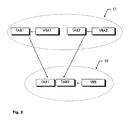
- FIG. 2 are the ones out FIG. 1 known, to be validated configuration data KD divided into two subsets TAB1 and TAB2, eg in two data tables, which also in FIG. 2 through that FIG. 1 known validation module VM are validated.
- the validation module VM initially determines, in the manner described above, which validation rule sets VR1 and VR2 must be used to validate the configuration data KD. Then the validation module VM performs the actual validation on the basis of the validation rules contained in the determined validation rule set.
- FIG. 2 These validation rules are shown in the form of validation rules VRA1, VRA2 and VRB, which follow the example FIG. 1 following in the validation rule set VR2.
- the validation module VM checks the configuration data KD in accordance with the validation rules VRA1, VRA2 and VRB in a partial examination S1 and a partial examination S2, which in FIG. 2 each indicated by dashed lines.
- the sub-sets TAB1 and TAB2 are individually checked by the validation module VM, namely the subset TAB1 on the basis of the validation rule VRA1 and the subset TAB2 on the basis of the validation rule VRA2. It can be checked, for example, whether the subset TAB1 only records each with a six-digit number and a first identifier and the subset TAB2 only records that each consist of a phone number and a second identifier.
- the validation module VM checks in the partial check 52 whether the subsets TAB1 and TAB2 are mutually consistent. For this purpose, the validation module VM applies the validation rule VRB. In this example, it is specified that each phone number from the subset TAB1 must also be contained in at least one record of the subset TAB2. The results of the partial tests S1 and S2 are reported by the validation module VM as in FIG. 1 with the help of a message MSG.
- the validation engine VM can sequentially and completely apply all the validation rules contained in a validation rule set to the configuration data KD.
- the validation module VM is predefined by means of control data to perform only a partial validation of the configuration data KD, that is, to use only a part of the validation rules of a validation rule set.
- the validation module VM can e.g. instructed to carry out only the partial test S1 on the basis of the validation rules VRA1 and VR2.
- the validation module VM can work very efficiently in this way since it only needs to read in and evaluate the validation rules actually required for validation.
- the validation rules VRA1 and VRA2 are contained in a first validation rule set, eg the validation rule set VR1, and the validation rule VRB in a second validation rule set, eg the validation rule set VR2.
- the validation module VM determines that only the validation rule set VR1 is involved is required, then reads only the validation rule set VR1 and checks for its validation rules. Only if both partial checks S1 and S2 are required does the validation module VM use both the validation rule set VR1 and the validation rule set VR2 for the desired validation of the configuration data KD.
- the validation module VM is shown in its essential functional steps.
- the validation module VM is, as already mentioned, stored in a memory and by a control means, such as a processor, readable and directly executable or indirectly evaluable using an interpreter program module command sequences.
- the validation module is VM in FIG. 3 represented in the form of a flowchart, in the course of which individual steps are executed.
- the individual steps each represent a single command or a sequence of commands, each of which forms a functional unit, a so-called function.
- the number of steps in FIG. 3 and their sequence is to be regarded as exemplary for a practical solution.
- the validation module VM detects in a step ST1 configuration data which are sent, for example via the interface device IF or the keypad KEY to the validation module VM.
- the instructions of step ST1 are combined in a receiving functional unit, for example in a subroutine.
- the validation module VM determines which validation rule set is required for the validation of the acquired configuration data KD.
- the validation module VM reads the determined validation rule set and then evaluates the first validation rule contained therein in a step ST4.
- the validation module VM checks the configuration data according to the rules of the validation rule evaluated in step ST4.
- a step ST6 it is checked whether the Validation module VM after fulfillment of step ST5 should evaluate further validation rules. If this is the case, the validation module VM branches back to the step ST4. Otherwise, the validation module VM ends in a step END.
Landscapes
- Engineering & Computer Science (AREA)
- Computer Networks & Wireless Communication (AREA)
- Signal Processing (AREA)
- Databases & Information Systems (AREA)
- Exchange Systems With Centralized Control (AREA)
- Maintenance And Management Of Digital Transmission (AREA)
- Computer And Data Communications (AREA)
- Inspection Of Paper Currency And Valuable Securities (AREA)
- Communication Control (AREA)
- Radar Systems Or Details Thereof (AREA)
- Mobile Radio Communication Systems (AREA)
- Telephonic Communication Services (AREA)
- Monitoring And Testing Of Exchanges (AREA)
Description
- Die vorliegende Erfindung betrifft ein Verfahren zur Validierung von Konfigurationsdaten als Betriebsparameter von Telekommunikationssystemen, sowie ein Validierungsmodul gemäß dem Oberbegriff des Anspruchs 7 hierfür, einen Server gemäß dem Oberbegriff des Anspruchs 8 hierfür, ein Steuermodul und ein Speichermittel hierfür.
- Ein solches Verfahren ist bekannt aus dem
US-Patent 5,713,075 . - Telekommunikationssysteme, z.B. Vermittlungsstellen, Zugangssysteme, Cross-Connects, Netzwerk Management Systeme, Rechnernetzwerke etc., werden im allgemeinen durch in gewissen Grenzen wählbare Konfigurationsdaten an spezielle Erfordernisse angepaßt, die durch den jeweiligen Einsatzbereich bestimmt werden. Gemäß der Vorgaben solcher Konfigurationsdaten kann eine in einem Telekommunikationssystem enthaltene Steuerungssoftware das Telekommunikationssystem in dem jeweiligen Einsatzbereich bestimmungsgemäß steuern. Einer modernen digitalen Vermittlungsstelle muß z.B. durch entsprechende Konfigurationsdaten unter anderem vorgegeben werden, welche Teilnehmeranschlüsse die Vermittlungsstelle zu bedienen hat, welche Rufnummern diesen jeweils zugeordnet sind und welche Telekommunikationsdienste den jeweiligen Teilnehmeranschlüssen zur Verfügung gestellt werden. Die Konfigurationsdaten eines solchen Teilnehmeranschlusses müssen dabei vorgegebenen Regeln genügen. So darf z.B. eine Rufnummer eines Teilnehmeranschlusses nur Zahlzeichen und keine Buchstabenzeichen enthalten und muß aus einer vorgegebenen Anzahl von Zahlzeichen bestehen. Ferner ist es meist nur dann möglich, einen Telekommunikationsdienst einem Teilnehmeranschluß zuzuweisen, wenn dessen Rufnummer zu einer für den jeweiligen Telekommunikationsdienst vorgesehenen Rufnummerngruppe gehört. Beispielsweise können für ein ISDN-Telekommunikationsnetz (Integrated Services Digital Network) definierte Dienste in vollem Umfang nur für einen ISDN-fähigen Teilnehmeranschluß eingerichtet werden. Bereits für einen einzelnen Teilnehmeranschlusses sind also die bei der Erstellung von dessen Konfigurationsdaten einzuhaltenden Bedingungen schon sehr umfangreich und kompliziert. Da jedoch zwischen einzelnen Teilnehmeranschlüssen einer Vermittlungsstelle in Bezug auf Konfigurationsdaten wechselseitige Beziehungen bestehen, z.B. weil mehrere Teilnehmeranschlüsse an eine gemeinsame Anschlußbaugruppe angeschlossen werden, müssen auch die durch die wechselseitigen Beziehungen erforderlichen Bedingungen bei der Erstellung der Konfigurationsdaten eingehalten werden. Da eine Steuerungssoftware eines Telekommunikationssystemes nur dann korrekt arbeiten kann, wenn die ihr als Betriebsparameter vorgegebenen Konfigurationsdaten richtig und in sich konsistent sind, müssen die Konfigurationsdaten vor deren Eingabe in das Telekommunikationssystem geprüft werden. Ein solcher Vorgang wird als Validierung bezeichnet.
- Konfigurationsdaten könnten zwar durch das zu konfigurierende Telekommunikationssystem selbst geprüft werden. Da jedoch, wie im obigen Beispiel bereits angedeutet, Konfigurationsdaten für ein Telekommunikationssystem meist sehr umfangreich sind und komplizierten Bedingungen genügen müssen, wäre dann in dem Telekommunikationssystem eine umfangreiche "Prüfsoftware" erforderlich, welche in dem Telekommunikationssystem für andere Zwecke dringender gebrauchte Ressourcen benötigen würde, z.B. Speicherplatz. Deshalb werden solche Konfigurationsdaten mit Hilfe eines Konfigurationssystemes erstellt, das jeweils für Konfigurationsdaten eines Telekommunikationssystem oder eines Typs eines solchen Telekommunikationssystemes geeignet ist. Ein typisches Beispiel für ein solches Konfigurationssystem ist in der Europäischen Patentanmeldung
EP 0 678 817 A1 dargestellt. Dort werden von einem Computer mit Hilfe einer graphischen Bedienoberfläche Konfigurationsdaten erfaßt und nach der Eingabe mit Hilfe eines Programmodules einer Überprüfung ihrer Konsistenz, also einer Validierung unterzogen. Erst dann werden die Konfigurationsdaten in eine Datenbank geschrieben und anschließend in einen Zustand weiterverarbeitet, in dem sie in ein "Zielsystem" genanntes Telekommunikationssystem geladen werden können. Sowohl die graphische Bedienoberfläche als auch das Programmodul zur Validierung der Konfigurationsdaten und die in dem Validierungs-Programmodul enthaltenen Validierungsregeln sind - wie allgemein üblich - speziell für die zu erfassenden Konfigurationsdaten vorgesehen und programmiert, im vorliegenden Beispiel in der Programmiersprache "Omnis 7". Eine solcherart "fest" programmierte graphische Bedienoberfläche sowie ein ebenfalls "fest" programmiertes zugehöriges Validierungs-Programmodules sind nur jeweils für die Erstellung von Konfigurationsdaten für ein bestimmtes Ziel-Telekommunikationssystem optimiert und geeignet, so daß für jedes Ziel-Telekommunikationssystem oder jeden Typ eines solchen Systems jeweils ein speziell für das jeweilige Ziel-Telekommunikationssystem geeignetes Konfigurationssystem erstellt und eingesetzt werden muß. - Sofern sich die Bedingungen ändern, denen Konfigurationsdaten genügen müssen, z.B. weil eine neue Steuersoftware eines Telekommunikationssystemes Konfigurationsdaten in anderer Form oder in anderem Umfang verlangt oder weil in Konfigurationsdaten zusätzlich neue Datentypen zur Konfiguration neuer Leistungsmerkmale enthalten sind, muß auch ein für die neuen Konfigurationsdaten geeignetes neues Validierungsprogrammodul erstellt werden oder ein bestehendes Validierungsprogrammodul zumindest teilweise neu programmiert und anschließend compiliert werden. Ein neues Validierungsprogrammodul zu erstellen ist jedoch einerseits zeitraubend und nur mit Hilfe von Programmierwerkzeugen möglich. Andrerseits unterlaufen bei einer solchen Neuprogrammierung leicht Fehler, die durch umfangreiches Testen des neuen oder des modifizierten Validierungsprogrammoduls ermittelt und anschließend behoben werden müssen.
- Aufgabe der Erfindung ist es, Konfigurationsdaten eines Telekommunikationssystemes auf effiziente Weise nach für das jeweils mit den Konfigurationsdaten arbeitende Telekommunikationssystem erforderlichen Validierungsregeln zu validieren.
- Diese Aufgabe wird durch ein Verfahren zur Validierung von Konfigurationsdaten für Telekommunikationssysteme gemäß der technischen Lehre des Anspruchs 1, sowie ein Validierungsmodul gemäß der technischen Lehre des Anspruchs 7, einen Server gemäß der technischen Lehre des Anspruchs 8, ein Steuermodul gemäß der technischen Lehre des Anspruchs 9 und ein Speichermittel gemäß der technischen Lehre des Anspruchs 10 gelöst. Weitere vorteilhafte Ausgestaltungen der Erfindung sind den abhängigen Ansprüchen und der Beschreibung zu entnehmen.
- Der Erfindung liegt hierbei der Gedanke zugrunde, ein Validierungsmodul, ein auf einem Computer ausführbares Programmodul, so zu gestalten, daß das Validierungsmodul Validierungsregeln, die jeweils für die Validierung von Konfigurationsdaten eines Telekommunikationssystem erforderlich sind und in einem Validierungsregelsatz abgelegt sind, vor der eigentlichen Validierung der Konfigurationsdaten ermittelt. Einen so ermittelten Validierungsregelsatz liest das Validierungsmodul dann aus einem Speicher aus und prüft die Konfigurationsdaten nach den in dem Validierungsregelsatz enthaltenen Validierungsregeln. Die Validierungsregeln sind erfindungsgemäß also nicht in dem eigentlichen Validierungsmodul enthalten, sondern werden abhängig von den zu prüfenden Konfigurationsdaten jeweils neu eingelesen und durch das Validierungsmodul ausgewertet.
- In einer Ausgestaltung der Erfindung liest das Validierungsmodul Steuerdaten ein, in denen der zu den Konfigurationsdaten gehörige Validierungsregelsatz definiert ist. In einer weiteren Ausgestaltung der Erfindung ermittelt das Validierungsmodul anhand eines Kennzeichners, der in den zu prüfenden Konfigurationsdaten enthalten ist, welcher Validierungsregelsatz zur Prüfung der Konfigurationsdaten heranzuziehen ist. In einer Variante der Erfindung sind die Validierungsregeln eines Validierungsregelsatzes in einer sogenannten Interpretersprache verfaßt und werden bei der Prüfung der Konfigurationsdaten von dem Validierungsmodul interpretiert. Es ist jedoch auch möglich, daß die Validierungsregeln bereits in einer von einem Prozessor ausführbaren Sprache verfaßt sind und als sogenannte Funktionen von dem Validierungsmodul in den Prüfungsprozess direkt eingebunden werden.
- Im folgenden werden die Erfindung und ihre Vorteile anhand eines Ausführungsbeispiels unter Zuhilfenahme der Zeichnungen dargestellt.
- Figur 1
- zeigt ein sehr schematisches Beispiel einer Anordnung zur Ausführung des erfindungsgemäßen Verfahrens mit einem erfindungsgemäßen Validierungsmodul (VM), Validierungsregelsätzen (VR1, VR2), zu validierenden Konfigurationsdaten (KD) und einer Meldung (MSG).
- Figur 2
- zeigt eine weitere schematische Anordnung zur Ausführung des erfindungsgemäßen Verfahrens mit Konfigurationsdaten in zwei Teilmengen (TAB1, TAB2) und drei unterschiedlichen Validierungsregeln (VRA1, VRA2 und VRB).
- Figur 3
- zeigt ein Ablaufdiagramm eines erfindungsgemäßen Validierungsmodules (VM).
- Figur 4
- zeigt einen erfindungsgemäßen Server (SER) zur Ausführung des erfindungsgemäßen Verfahrens.
-
Figur 1 zeigt ein sehr schematisches Beispiel einer Anordnung zur Ausführung des erfindungsgemäßen Verfahrens. Dort ist ein erfindungsgemäßes Validierungsmodul VM dargestellt, das als ein Programmodul auf einem Computer, z.B. einem Personal Computer oder einer Workstation, ausführbar ist und Konfigurationsdaten, beispielhaft dargestellt durch Konfigurationsdaten KD, universell für verschiedenartige Telekommunikationssysteme validieren kann. Ein Beispiel für ein Telekommunikationssystem ist in Form eines Zielsystemes TS inFigur 1 gezeigt. Das Zielsystem TS kann mit Konfigurationsdaten KD konfiguriert werden. Das Zielsystem TS kann z.B. eine Vermittlungsstelle oder ein Netzwerk-Management-System sein. Die Konfigurationsdaten KD enthalten z.B. Daten über Verbindungen, die von dem Zielsystem TS geschaltet werden können oder Daten, die von dem Zielsystem TS bediente Teilnehmeranschlüsse definieren. Das Zielsystem TS kann jedoch auch z.B. eine Fernwirk-Unterstation sein. Die Konfigurationsdaten KD enthalten dann z.B. Daten über Messwerte und Befehle, die die Fernwirk-Unterstation erfassen bzw. ausgeben soll. - Ein Computer zur Ausführung des Validierungsmodules VM ist in einigen wesentlichen Komponenten ist in
Figur 4 als Server SER dargestellt. Der Server SER enthält ein Steuermittel CPU, z.B. einen Prozessor, zur Ausführung maschinenlesbarer Befehle, z.B. zur Ausführung des Validierungsmodules VM. - Ferner weist der Server SER einen Speicher MEM auf, in dem das Validierungsmodul VM gespeichert sein kann. Außerdem verfügt der Server SER als Eingabemittel und Ausgabemittel über ein Tastenfeld KEY und über eine Anzeigevorrichtung DIS, z.B. um Daten auszugeben, die von dem Validierungsmodul VM erzeugt werden, oder um Daten an das Validierungsmodul VM zu senden. Ferner verfügt der Server SER über eine Schnittstellenvorrichtung IF, über die er Daten mit dem aus
Figur 1 bekannten Zielsystem TS austauschen kann. Die Komponenten des Servers SER sind durch inFigur 4 nicht dargestellte Verbindungen miteinander verbunden. Ein Betriebssystem, z.B. UNIX oder DOS (Disc Operating System), verwaltet die Betriebsmittel des Servers SER und steuert unter anderem die Ausführung des Validierungsmodules VM. Zur weiteren Darstellung der Erfindung wird wieder dieFigur 1 betrachtet, wobei auch auf Komponenten des inFigur 4 dargestellten Servers SER verwiesen wird. - Das Validierungsmodul VM kann die Konfigurationsdaten KD nach einer oder mehreren Validierungsregeln validieren, die in einem Validierungsregelsatz enthalten sind. Beispiele für solche Validierungsregelsätze sind in Form eines Validierungsregelsatzes VR1 und eines Validierungsregelsatzes VR2 in
Figur 1 gezeigt. Die Validierungsregelsätze VR1 und VR2 stehen beispielhaft für weitere, inFigur 1 nicht dargestellte Validierungsregelsätze und sind in dem Speicher MEM abgelegt. Die Konfigurationsdaten KD werden von dem Zielsystem TS an das Validierungsmodul VM gesendet oder von einem inFigur 1 nicht gezeigten Programmodul erfaßt, z.B. von einem Editor oder einer graphischen Bedienoberfläche oder über die Schnittstellenvorrichtung IF eingelesen. Anschließend werden die Konfigurationsdaten KD dem Validierungsmodul VM übermittelt, z.B. in Form einer Datei, die in dem Speicher MEM abgelegt ist, oder mit Hilfe von Nachrichten, die an das Validierungsmodul VM gesendet werden. Der Vorgang des Übermittelns ist inFigur 1 durch einen Pfeil angedeutet. - Nachdem das Validierungsmodul VM die Konfigurationsdaten KD erfaßt hat, ermittelt das Validierungsmodul VM, nach welchen Validierungsregeln die Konfigurationsdaten KD zu prüfen sind. Dazu verwendet das Validierungsmodul VM Steuerdaten VCONF, in denen angegeben ist, in welchem Validierungsregelsatz die erforderlichen Validierungsregeln enthalten sind. Die Steuerdaten können z.B. in Form einer Steuertabelle abgelegt sein, in der jeweils eine Zuordnung von Konfigurationsdaten zu einem Validierungsregelsatz definiert ist. Dort kann z.B. festgelegt sein, daß ein bestimmter Typ eines Zielsystemes Konfigurationsdaten benötigt, die anhand des Validierungsregelsatzes VR1 zu prüfen sind, ein anderer Typ eines Zielsystemes jedoch Konfigurationsdaten, die dem Validierungsregelsatz VR2 standhalten müssen. In dem Beispiel aus
Figur 1 ist in den Steuerdaten VCONF festgelegt, daß die Konfigurationsdaten KD nach den Vorgaben des Validierungsregelsatzes VR2 zu prüfen sind. Das Validierungsmodul VM liest den Validierungsregelsatz VR2 aus dem Speicher MEM ein und prüft die Konfigurationsdaten KD nach den Vorgaben des Validierungsregelsatzes VR2. Das Ergebnis der Prüfung meldet das Validierungsmodul VM mit einer Meldenachricht MSG, z.B. in Form einer Ausgabe an der Anzeigevorrichtung DIS oder auf einem Drucker. Mit Hilfe der Meldenachricht MSG können bei der Prüfung aufgetretene Fehler auch detailliert angezeigt werden. Wenn die von dem Validierungsmodul VM überprüften Konfigurationsdaten KD der Überprüfung standgehalten haben, also konsistent sind, können die Konfigurationsdaten KD z.B. über die Schnittstellenvorrichtung IF in das Zielsystem TS geladen und von diesem als Betriebsparameter übernommen werden. - Wenn sich die Erfordernisse geändert haben, welche die Konfigurationsdaten KD für einen korrekten Betrieb des Zielsystemes TS erfüllen müssen, genügt es, lediglich den Validierungsregelsatz VR2 auszutauschen oder so zu modifizieren, daß die in dem neuen oder modifizierten Validierungsregelsatz VR2 enthaltenen Validierungsregeln eine vollständige, an die neuen Erfordernisse des Zielsystemes TS angepaßte Validierung sicherstellen. Das Validierungsmodul VM an sich muß nicht geändert werden. Auf diese Weise ist es auch leicht möglich, weitere Validierungsregeln in einen Validierungsregelsatz einzufügen oder nicht mehr benötigte Validierungsregeln aus einem Validierungsregelsatz zu entfernen. Soll das Validierungsmodul VM Konfigurationsdaten validieren, die weder mit dem Validierungsregelsatz VR1 noch mit dem Validierungsregelsatz VR2 validierbar sind, kann auch jederzeit ein neuer Validierungsregelsatz zu den Validierungsregelsätzen VR1 und VR2 hinzugefügt werden, mit dem die neuen Konfigurationsdaten validiert werden können.
- Wenn in den Validierungsregelsätzen VR1 oder VR2 Vorgabeinformationen, z.B. Textelemente, für einen Inhalt der Meldenachricht MSG enthalten, kann das Validierungsmodul VM diese Vorgabeinformationen zur Gestaltung der Meldenachricht MSG verwenden. So kann z.B. in den Validierungsregelsätzen VR1 oder VR2 für jede der dort enthaltenen Validierungsregeln festgelegt sein, welche Fehlermeldung von dem Validierungsmodul VM anzuzeigen ist, wenn bei einer Prüfung nach den Vorgaben der jeweiligen Validierungsregel ein Fehler auftritt. Weil die Vorgabeinformationen für die Meldenachricht MSG nicht Bestandteil des Validierungsmodules VM sind, sondern jeweils aus einem Validierungsregelsatz ausgelesen werden, können diese Vorgabeinformationen genauso wie die Validierungsregeln leicht ausgetauscht oder modifiziert werden, um so aktuellen Erfordernissen gerecht zu werden. Damit kann z.B. ein neu in einen Validierungsregelsatz eingefügter Text für eine Fehlermeldung eine Ursache für einen Fehler näher präzisieren.
- Mit Hilfe der Steuerdaten VCONF kann dem Validierungsmodul VM auch schon vor dem Einlesen der Konfigurationsdaten KD ermitteln, mit welchem der Validierungsregelsätze VR1 oder VR2 die Konfigurationsdaten KD zu prüfen sind, z.B. wenn die Steuerdaten VCONF als sogenannte Aufrufparameter dem Validierungsmodul VM schon bei dessen Start mitgegeben werden.
- Es ist jedoch auch zusätzlich oder alternativ zu der Ermittlung eines Validierungsregelsatzes anhand von Steuerdaten möglich, daß das Validierungsmodul VM anhand der Konfigurationsdaten KD ermittelt, welcher der Validierungsregelsätze VR1 oder VR2 zur Prüfung der Konfigurationsdaten KD benötigt wird. Dazu sucht das Validierungsmodul VM in den Konfigurationsdaten KD nach einem Merkmal oder einem Identifizierer, der die Konfigurationsdaten KD eindeutig kennzeichnet. Ein solcher Identifizierer ist in Form eines Identifizierers ID2 in den Konfigurationsdaten KD enthalten. Der Identifizierer ID2 kann die Konfigurationsdaten KD z.B. als zu einem bestimmten Zielsystem, in
Figur 1 der Zielsystem TS, zugehörig ausweisen und ein Textelement mit dem Inhalt sein: "Vermittlungsstelle A mit Steuersoftware Version 1.3". Anhand von beispielsweise in einer Zuordnungstabelle enthaltenen Zuordnungen von jeweils einem solchen Identifizierer zu einem der Validierungsregelsätze kann dann das Validierungsmodul VM feststellen, welcher Validierungsregelsatz zur Prüfung der Konfigurationsdaten KD zu verwenden ist. Es ist auch möglich, daß das Validierungsmodul VM den zur Validierung der Konfigurationsdaten KD erforderlichen Validierungsregelsatz VR1 oder VR2 anhand eines Identifizierers ermittelt, der gleich lauten muß wie derjenige, der in den Konfigurationsdaten KD enthalten ist. Der Identifizierer ID2 der Konfigurationsdaten KD ist in dem Beispiel ausFigur 1 auch in dem Validierungsregelsatz VR2 angegeben; der Validierungsregelsatz VR1 dagegen weist einen Identifizierer ID1 auf. - Wenn kein Identifizierer in den Konfigurationsdaten KD enthalten ist, z.B. weil ein solcher Identifizierer das Zielsystem TS bei der Verarbeitung der Konfigurationsdaten KD stören würde, kann das Validierungsmodul VM auch anhand der Struktur und der Art der Konfigurationsdaten KD ermitteln, welcher Validierungsregelsatz zur Prüfung verwendet muß. Wenn - in einem sehr einfachen Beispiel - die Konfigurationsdaten KD nur Datensätze enthalten, die jeweils mit einer Zahlenkette beginnen, kann das Validierungsmodul VM z.B. daraus ableiten, daß die Konfigurationsdaten KD nach dem Validierungsregelsatz VR1 zu prüfen sind. Wenn die Konfigurationsdaten KD jedoch nur Datensätze enthalten, die jeweils mit einer Buchstabenkette beginnen, kann das Validierungsmodul VM daran erkennen, daß die Konfigurationsdaten KD nach dem Validierungsregelsatz VR2 zu prüfen sind.
- Die in den Validierungsregelsätzen VR1 und VR2 enthaltenen Validierungsregeln müssen durch die Gestaltung des Validierungsmodules VM vorgegebenen semantischen und syntaktischen Regeln entsprechen. Zur Erfüllung solcher Regeln können die Validierungsregeln in einer sogenannten Interpretersprache verfaßt sein, deren Anweisungen das Validierungsmodul VM "interpretieren", also auswerten und in maschinenlesbare Befehle umsetzen kann. Diese Befehle kann dann das Steuermittel CPU in ähnlicher Weise ausführen wie die Befehlssequenzen des Validierungsmodules VM. Eine Interpretersprache für Validierungsregeln kann für das Validierungsmodul VM eigens definiert werden. Es ist jedoch auch möglich, eine universell für verschiedene Zwecke geeignete Interpretersprache einzusetzen. Ein Beispiel für eine universelle Interpretersprache ist die Sprache PERL (Practical Extraction and Report Language), die im Zusammenhang mit dem Betriebssystem UNIX gebräuchlich ist. Wenn die Validierungsregeln in PERL verfaßt sind, muß das Validierungsmodul VM die Validierungsregeln nicht unbedingt selbst interpretieren, sondern kann ein "PERL-Interpreter" genanntes Programmodul mit der Interpretation der Validierungsregeln beauftragen. Ein PERL-Interpreter gehört üblicherweise zum Lieferumfang eines UNIX Betriebssystemes. Die von dem PERL-Interpreter aus den Validierungsregeln erzeugten maschinenlesbaren Befehle werden von dem Validierungsmodul VM in dessen eigene Befehlssequenzen eingebunden, z.B. in Form von Programmverzweigungen.
- Besonders einfach ist dieser Prozeß des Einbindens von Validierungsregeln in das Validierungsmodul VM dann, wenn sowohl das Validierungsmodul VM als auch die einzubindenden Validierungsregeln in derselben Interpretersprache verfaßt sind. Dann kann in dem Validierungsmodul VM ein allgemeiner Aufruf enthalten sein, der auf eine Validierungsregel verweist, die einen in dem Aufruf angegebenen Namen trägt. Der Aufruf verweist jedoch, je nachdem welcher der Validierungsregelsätze VR1 oder VR2 zu der Validierung verwendet werden muß, entweder auf eine Validierungsregel in dem Validierungsregelsatz VR1 oder auf eine Validierungsregel in dem Validierungsregelsatz VR2. Beide Validierungsregeln tragen zwar den gleichen Namen, können aber unterschiedliche Prüfvorschriften enthalten. Für eine korrekte Verzweigung der Befehlssequenzen des Validierungsmodules VM in die durch Interpretieren der Validierungsregeln erzeugten Befehlssequenzen sorgt in diesem Fall das Interpreter-Programmodul.
- Die Validierungsregeln können in den Validierungsregelsätze VR1 und VR2 auch bereits in einer von einem Prozessor ausführbaren Form, als sogenannte Funktionen, auch Bibliotheksfunktionen genannt, enthalten sein. Das Validierungsmodul VM kann die Befehlssequenzen solcher Funktionen ohne vorherige Interpretation direkt in seine eigenen Befehlssequenzen einbinden. Ein solcher Vorgang wird auch als "dynamisches Linken" von Funktionen bezeichnet. In einer weiteren Variante der Erfindung können solche Funktionen auch erst zur Laufzeit des Validierungsmodules VM erzeugt werden, indem das Validierungsmodul VM einen zur Validierung der Konfigurationsdaten KD zu verwendenden Validierungsregelsatz zunächst in von einem Prozessor ausführbare Befehlssequenzen übersetzt oder durch ein Übersetzer-Programmodul übersetzen läßt und die so erzeugten Validierungsregel-Befehlssequenzen in seine eigenen Befehlssequenzen einbindet.
- Anhand von
Figur 2 wird im folgenden die Erfindung detaillierter dargestellt und ein weiterer Aspekt der Erfindung verdeutlicht, der durch das erfindungsgemäße, dynamische Einbinden von Validierungsregeln jeweils zu einem bestimmten Validierungsvorgang ermöglicht wird. InFigur 2 sind die ausFigur 1 bekannten, zu validierenden Konfigurationsdaten KD in zwei Teilmengen TAB1 und TAB2 aufgeteilt, z.B. in zwei Datentabellen, die auch inFigur 2 durch das ausFigur 1 bekannte Validierungsmodul VM validiert werden. Das Validierungsmodul VM ermittelt zunächst in der oben dargestellten Weise, welcher Validierungsregelsätze VR1 und VR2 zur Validierung der Konfigurationsdaten KD verwendet werden muß. Dann führt das Validierungsmodul VM die eigentliche Validierung anhand der in dem ermittelten Validierungsregelsatz enthaltenen Validierungsregeln durch. InFigur 2 sind diese Validierungsregeln in Form von Validierungsregeln VRA1, VRA2 und VRB dargestellt, die dem Beispiel ausFigur 1 folgend in dem Validierungsregelsatz VR2 enthalten sind. - Das Validierungsmodul VM prüft gemäß den Validierungsregeln VRA1, VRA2 und VRB die Konfigurationsdaten KD in einer Teilprüfung S1 und einer Teilprüfung S2, die in
Figur 2 jeweils durch gestrichelte Linien angedeutet sind. Bei der Teilprüfung S1 werden die Teilmengen TAB1 und TAB2 von dem Validierungsmodul VM jeweils einzeln geprüft und zwar die Teilmenge TAB1 anhand der Validierungsregel VRA1 und die Teilmenge TAB2 anhand der Validierungsregel VRA2. Dabei kann z.B. überprüft werden, ob die Teilmenge TAB1 nur Datensätze mit jeweils einer sechsstelligen Rufnummer und einer ersten Kennung enthält und die Teilmenge TAB2 nur Datensätze, die jeweils aus einer Rufnummer und einer zweiten Kennung bestehen. Wenn die Teilmengen TAB1 und TAB2 jeweils der Teilprüfung S1 standgehalten haben, also in sich konsistent sind, prüft das Validierungsmodul VM in der Teilprüfung 52, ob die Teilmengen TAB1 und TAB2 wechselseitig konsistent sind. Dazu wendet das Validierungsmodul VM die Validierungsregel VRB an. In dieser wird z.B. vorgegeben, daß jede Rufnummer aus der Teilmenge TAB1 auch in mindestens einem Datensatz der Teilmenge TAB2 enthalten sein muß. Die Ergebnisse der Teilprüfungen S1 und S2 meldet das Validierungsmodul VM wie inFigur 1 mit Hilfe einer Meldenachricht MSG. - Wie im obigen Abschnitt beschrieben, kann das Validierungsmodul VM alle in einem Validierungsregelsatz enthaltene Validierungsregeln nacheinander und vollständig auf die Konfigurationsdaten KD anwenden. Es ist jedoch auch möglich, daß dem Validierungsmodul VM mit Hilfe von Steuerdaten vorgegeben wird, nur eine Teilvalidierung der Konfigurationsdaten KD durchzuführen, also nur einen Teil der Validierungsregeln eines Validierungsregelsatzes anzuwenden. So kann das Validierungsmodul VM z.B. angewiesen werden, nur die Teilprüfung S1 anhand der Validierungsregeln VRA1 und VR2 vorzunehmen. Das Validierungsmodul VM kann auf diese Weise sehr effizient arbeiten, da es nur die zur Validierung tatsächlich erforderlichen Validierungsregeln einlesen und auswerten muß.
- Zur Darstellung einer weiteren Variante der Erfindung sei angenommen, daß die Validierungsregeln VRA1 und VRA2 in einem ersten Validierungsregelsatz, z.B. dem Validierungsregelsatz VR1, enthalten sind und die Validierungsregel VRB in einem zweiten Validierungsregelsatz, z.B. dem Validierungsregelsatz VR2. Wenn das Validierungsmodul VM dazu angewiesen wird, nur die Teilprüfung S1 durchzuführen, ermittelt das Validierungsmodul VM, daß dazu nur der Validierungsregelsatz VR1 erforderlich ist, liest dann auch nur den Validierungsregelsatz VR1 ein und prüft nach dessen Validierungsregeln. Nur wenn beide Teilprüfungen S1 und S2 verlangt sind, zieht das Validierungsmodul VM sowohl den Validierungsregelsatz VR1 als auch den Validierungsregelsatz VR2 zu der gewünschten Validierung der Konfigurationsdaten KD heran.
- In
Figur 3 ist das Validierungsmodul VM in seinen wesentlichen Funktionsschritten dargestellt. Das Validierungsmodul VM besteht, wie schon erwähnt, aus in einem Speicher gespeicherten und von einem Steuermittel, z.B. von einem Prozessor, lesbaren und unmittelbar ausführbaren oder mit Hilfe eines Interpreter-Programmodules indirekt auswertbaren Befehlssequenzen. Im Interesse einer leicht verständlichen Darstellung ist das Validierungsmodul VM inFigur 3 in Form eines Ablaufdiagrammes dargestellt, in dessen Ablauf einzelne Schritte ausgeführt werden. Die einzelnen Schritte stehen jeweils für einen einzelnen Befehl oder eine Folge von Befehlen, die jeweils eine funktionale Einheit, eine sogenannte Funktion, bilden. Die Anzahl der Schritte inFigur 3 sowie deren Ablauf ist als beispielhaft für eine praxisgerechte Lösung anzusehen. Ausgehend von einem Startfeld START erfaßt das Validierungsmodul VM in einem Schritt ST1 Konfigurationsdaten, die z.B. über die Schnittstellenvorrichtung IF oder das Tastenfeld KEY an das Validierungsmodul VM gesendet werden. Die Anweisungen des Schrittes ST1 sind in einer Empfangsfunktionseinheit, z.B. in einem Unterprogramm, zusammengefaßt. In einem Schritt ST2 ermittelt das Validierungsmodul VM, welcher Validierungsregelsatz zu der Validierung der erfaßten Konfigurationsdaten KD erforderlich ist. In einem Schritt ST3 liest das Validierungsmodul VM den ermittelten Validierungsregelsatz ein und wertet anschließend die erste darin enthaltene Validierungsregel in einem Schritt ST4 aus. In einem Schritt ST5 prüft das Validierungsmodul VM die Konfigurationsdaten nach den Vorschriften der in Schritt ST4 ausgewerteten Validierungsregel. In einem Schritt ST6 wird überprüft, ob das Validierungsmodul VM nach Erfüllung des Schrittes ST5 weitere Validierungsregeln auswerten soll. Ist dies der Fall, verzweigt das Validierungsmodul VM wieder zu dem Schritt ST4. Ansonsten endet das Validierungsmodul VM in einem Schritt END.
Claims (10)
- Verfahren zur Validierung von Konfigurationsdaten (KD) als Betriebsparameter von Telekommunikationssystemen anhand von Validierungsregeln durch ein Validierungsmodul (VM), mit den Schritten:- Erfassen der Konfigurationsdaten,- Ermitteln eines Validierungsregelsatzes (VR2) mit mindestens einer Validierungsregel zur Validierung der Konfigurationsdaten,- Auswerten des Validierungsregelsatzes,- Prüfen der Konfigurationsdaten gemäß den Vorschriften des Validierungsregelsatzes und- Ausgeben einer Meldenachricht (MSG) mit einer Information über den Erfolg der Prüfung,dadurch gekennzeichnet, daß das Ermitteln eines Validierungsregelsatzes die Auswahl eines Validierungsregelsatzes aus einer Mehrzahl von mindestens zwei Validierungsregelsätzen (VR1, VR2) umfaßt, daß der ermittelte und ausgewählte Validierungsregelsatz eingelesen wird, und daß die Zuordnung von Konfigurationsdaten zu einem Validierungsregelsatz durch die Verwendung von Steuerdaten (VCONF) erfolgt.
- Verfahren nach Anspruch 1, dadurch gekennzeichnet, daß das Validierungsmodul (VM) den Validierungsregelsatz (VR2) aus für das Validierungsmodul bestimmten Steuerdaten (VCONF) ermittelt.
- Verfahren nach Anspruch 1, dadurch gekennzeichnet, daß der Validierungsregelsatz (VR) mit Hilfe eines in den Konfigurationsdaten (KD) enthaltenen Kennzeichners (ID1) ermittelt wird.
- Verfahren nach Anspruch 1, dadurch gekennzeichnet, daß bei dem Auswerten des Validierungsregelsatzes (VR2) Funktionsblöcke ermittelt und eingelesen werden, mit denen die Konfigurationsdaten (KD) entsprechend den in dem Validierungsregelsatz enthaltenen Validierungsregeln geprüft werden können, und daß zu der Prüfung der Konfigurationsdaten die Funktionsblöcke eingesetzt werden.
- Verfahren nach Anspruch 1, dadurch gekennzeichnet, daß bei dem Auswerten des Validierungsregelsatzes (VR2) aus den in dem Validierungsregelsatzes enthaltenen Validierungsregeln Funktionsblöcke erzeugt werden, mit denen die Konfigurationsdaten (KD) entsprechend den in dem Validierungsregelsatz enthaltenen Validierungsregeln geprüft werden können, und daß zu der Prüfung der Konfigurationsdaten die Funktionsblöcke eingesetzt werden.
- Verfahren nach Anspruch 1, dadurch gekennzeichnet, daß bei der Ausgabe der Meldenachricht (MSG) mit einer Information über den Erfolg der Prüfung Vorgabeinformationen verwendet werden, die in dem Validierungsregelsatz enthalten sind.
- Validierungsmodul (VM) zur Validierung von Konfigurationsdaten (KD) als Betriebsparameter von Telekommunikationssystemen anhand von Validierungsregeln, wobei das Validierungsmodul eine Empfangsfunktionseinheit aufweist, die so ausgestaltet ist, daß das Validierungsmodul die Konfigurationsdaten erfassen kann, wobei das Validierungsmodul eine Auswertefunktionseinheit aufweist, die so ausgestaltet ist, daß das Validierungsmodul den Validierungsregelsatz auswerten kann, wobei das Validierungsmodul eine Prüffunktionseinheit aufweist, die so ausgestaltet ist, daß das Validierungsmodul die Konfigurationsdaten gemäß den Vorschriften des Validierungsregelsatzes prüfen kann, und wobei das Validierungsmodul eine Ausgabefunktionseinheit aufweist, die so ausgestaltet ist, daß das Validierungsmodul eine Meldenachricht mit einer Information über den Erfolg der Prüfung ausgeben kann dadurch gekennzeichnet, daß das Validierungsmodul eine Ermittlungsfunktionseinheit aufweist, die so ausgestaltet ist, daß das Validierungsmodul einen Validierungsregelsatz mit mindestens einer Validierungsregel zur Validierung der Konfigurationsdaten ermitteln kann, wobei das Ermitteln eines Validierungsregelsatzes die Auswahl eines Validierungsregelsatzes aus einer Mehrzahl von mindestens zwei Validierungsregelsätzen (VR1, VR2) umfaßt und wobei die Zuordnung von Konfigurationsdaten zu einem Validierungsregelsatz durch die Verwendung von Steuerdaten (VCONF) erfolgt, und daß das Validierungsmodul eine Einlesefunktionseinheit aufweist, die so ausgestaltet ist, daß das Validierungsmodul den Validierungsregelsatz einlesen kann.
- Server (SER) zur Validierung von Konfigurationsdaten (KD) als Betriebsparameter von Telekommunikationssystemen anhand von Validierungsregeln, wobei der Server Empfangsmittel (IF, KEY) aufweist, die so ausgestaltet sind, daß der Server die Konfigurationsdaten erfassen kann, wobei der Server Auswertemittel aufweist, die so ausgestaltet sind, daß der Server den Validierungsregelsatz auswerten kann, wobei der Server Prüfmittel aufweist, die so ausgestaltet sind, daß der Server die Konfigurationsdaten gemäß den Vorschriften des Validierungsregelsatzes prüfen kann, und wobei der Server Ausgabemittel (DIS) aufweist, die so ausgestaltet sind, daß der Server eine Meldenachricht mit einer Information über den Erfolg der Prüfung ausgeben kann, dadurch gekennzeichnet, daß der Server Ermittlungsmittel aufweist, die so ausgestaltet sind, daß der Server einen Validierungsregelsatz mit mindestens einer Validierungsregel zur Validierung der Konfigurationsdaten ermitteln kann, wobei das Ermitteln eines Validierungsregelsatzes die Auswahl eines Validierungsregelsatzes aus einer Mehrzahl von mindestens zwei Validierungsregelsätzen (VR1, VR2) umfaßt und wobei die Zuordnung von Konfigurationsdaten zu einem Validierungsregelsatz durch die Verwendung von Steuerdaten (VCONF) erfolgt, und daß der Server Einlesemittel aufweist, die so ausgestaltet sind, daß der Server den Validierungsregelsatz einlesen kann.
- Steuermodul, auf dem ein Validierungsmodul abgespeichert ist und das dazu vorgesehen ist, im Zusammenhang mit einem Prozessor das Verfahren nach Anspruch 1 auszuführen.
- Speichermittel, dadurch gekennzeichnet, daß darauf ein Validierungsmodul (VM) nach Anspruch 7 gespeichert ist.
Applications Claiming Priority (2)
| Application Number | Priority Date | Filing Date | Title |
|---|---|---|---|
| DE19854753 | 1998-11-27 | ||
| DE19854753 | 1998-11-27 |
Publications (3)
| Publication Number | Publication Date |
|---|---|
| EP1005216A2 EP1005216A2 (de) | 2000-05-31 |
| EP1005216A3 EP1005216A3 (de) | 2003-01-29 |
| EP1005216B1 true EP1005216B1 (de) | 2008-11-19 |
Family
ID=7889212
Family Applications (1)
| Application Number | Title | Priority Date | Filing Date |
|---|---|---|---|
| EP99440323A Expired - Lifetime EP1005216B1 (de) | 1998-11-27 | 1999-11-19 | Verfahren und Vorrichtung zur Validierung von Konfigurationsdaten für Telekommunikationssysteme |
Country Status (5)
| Country | Link |
|---|---|
| EP (1) | EP1005216B1 (de) |
| JP (1) | JP4394225B2 (de) |
| AT (1) | ATE415044T1 (de) |
| AU (1) | AU6174699A (de) |
| DE (1) | DE59914907D1 (de) |
Families Citing this family (12)
| Publication number | Priority date | Publication date | Assignee | Title |
|---|---|---|---|---|
| ITTO20010180A1 (it) * | 2001-03-01 | 2002-09-01 | Cselt Centro Studi Lab Telecom | Procedimento e sistema per il controllo della configurazione dei nodidi una rete per telecomunicazione. |
| US7418484B2 (en) * | 2001-11-30 | 2008-08-26 | Oracle International Corporation | System and method for actively managing an enterprise of configurable components |
| ITTO20020742A1 (it) * | 2002-08-23 | 2004-02-24 | Telecom Italia Lab Spa | Procedimento e sistema per il controllo della |
| DE10336793B4 (de) * | 2003-08-08 | 2005-06-23 | Db Telematik Gmbh | Verfahren zur Einrichtung und Konfiguration von Telekommunikationsdiensten eines Mobilfunknetzes |
| US20060126530A1 (en) * | 2004-12-14 | 2006-06-15 | Nokia Corporation | Indicating a configuring status |
| US8615578B2 (en) | 2005-10-07 | 2013-12-24 | Oracle International Corporation | Using a standby data storage system to detect the health of a cluster of data storage servers |
| EP1841131A1 (de) * | 2006-03-28 | 2007-10-03 | Nokia Siemens Networks Gmbh & Co. Kg | Konfigurationsmanagement mit zusätzlichen Operationen |
| WO2009083683A1 (fr) * | 2007-12-20 | 2009-07-09 | France Telecom | Procede de configuration d'un equipement reseau |
| JP4937968B2 (ja) * | 2008-06-19 | 2012-05-23 | 富士通テレコムネットワークス株式会社 | 通信制御装置およびメッセージ生成方法 |
| CN110188038B (zh) * | 2019-05-13 | 2023-07-21 | 青岛海尔科技有限公司 | 一种参数校验方法及装置、校验架构 |
| CN111047295B (zh) * | 2019-12-13 | 2023-04-07 | 红云红河烟草(集团)有限责任公司 | 一种卷烟制丝加工过程的数据采集方法 |
| CN115277392A (zh) * | 2022-07-08 | 2022-11-01 | 南瑞集团有限公司 | 电力调度数据网设备配置合规性核查系统及方法 |
Family Cites Families (3)
| Publication number | Priority date | Publication date | Assignee | Title |
|---|---|---|---|---|
| EP0667722A1 (de) * | 1994-02-09 | 1995-08-16 | Koninklijke KPN N.V. | Verfahren zur Erkennung von Dienstwechselwirkungen in intelligenten Netzwerken |
| US5713075A (en) * | 1995-11-30 | 1998-01-27 | Amsc Subsidiary Corporation | Network engineering/systems engineering system for mobile satellite communication system |
| US5912960A (en) * | 1996-05-17 | 1999-06-15 | Alcatel Usa Sourcing, L.P. | Method and apparatus for remotely activating services in a telecommunications network |
-
1999
- 1999-11-19 AT AT99440323T patent/ATE415044T1/de not_active IP Right Cessation
- 1999-11-19 EP EP99440323A patent/EP1005216B1/de not_active Expired - Lifetime
- 1999-11-19 DE DE59914907T patent/DE59914907D1/de not_active Expired - Lifetime
- 1999-11-22 JP JP33089799A patent/JP4394225B2/ja not_active Expired - Fee Related
- 1999-11-26 AU AU61746/99A patent/AU6174699A/en not_active Abandoned
Also Published As
| Publication number | Publication date |
|---|---|
| JP2000216854A (ja) | 2000-08-04 |
| ATE415044T1 (de) | 2008-12-15 |
| EP1005216A2 (de) | 2000-05-31 |
| DE59914907D1 (de) | 2009-01-02 |
| AU6174699A (en) | 2000-06-01 |
| JP4394225B2 (ja) | 2010-01-06 |
| EP1005216A3 (de) | 2003-01-29 |
Similar Documents
| Publication | Publication Date | Title |
|---|---|---|
| DE69900810T2 (de) | Verfahren und Vorrichtung zum Testen von ereignisgesteuerten Programmen | |
| DE19837871C2 (de) | Verfahren zum automatischen Erzeugen eines Programms | |
| DE69529846T2 (de) | Verfahren zum vergleich von attributwerten von steuerbaren objektausdrücken in einem netzwerkelement | |
| DE69327777T2 (de) | Informationsbearbeitungseinrichtung, die die Führung von Betriebsmitteln durch ein Verwaltungssystem erlaubt | |
| DE69228819T2 (de) | Konfigurations- und Betriebsverfahren eines Telekommunikationsgeräts | |
| EP1430369B1 (de) | Dynamischer zugriff auf automatisierungsressourcen | |
| EP0525432A2 (de) | Verfahren zur Änderung von Systemkonfigurationsdatensätzen in einem Fernmeldevermittlungssystem | |
| DE69511080T2 (de) | Schnittstellenanordnung und verfahren | |
| DE3503119A1 (de) | Verfahren zum automatischen erzeugen eines quellenprogramms | |
| DE4125389C1 (de) | ||
| EP1035707A2 (de) | Verfahren, Erzeugungsmodul, Server, Steuermodul und Speichermittel zum Erstellen von Validierungsregeln | |
| DE19822553A1 (de) | Netzelement mit einer Steuerungseinrichtung und Steuerungsverfahren | |
| EP1005216A2 (de) | Verfahren und Vorrichtung zur Validierung von Konfigurationsdaten für Telekommunikationssysteme | |
| EP1005215B1 (de) | Verfahren und Vorrichtung zum Editieren von Konfigurationsdaten für Telekommunikationssysteme | |
| EP0977416B1 (de) | Verfahren, Endgerät, Knoten, Programmodul und Bedienoberfläche zur Ermittlung von für eine Kommunikationsbeziehung erforderlichen Merkmalen | |
| EP0303869B1 (de) | Modular strukturiertes digitales Kommunikationssystem mit betriebstechnischen Kommunikationsmitteln | |
| DE3727942A1 (de) | Modular strukturiertes digitales kommunikationssystem mit betriebstechnischen und sicherheitstechnischen komponenten | |
| DE69836751T2 (de) | Dienste mit rufunabhängigen modulen | |
| DE69828804T2 (de) | Einführung von dienst unabhängigen baublöcken | |
| EP0358597A2 (de) | Fernsprechvermittlungseinrichtung | |
| DE3924974A1 (de) | Fernsprechvermittlungseinrichtung | |
| DE102009019442A1 (de) | Testdatengenerator | |
| DE69333420T2 (de) | Verfahren und anordnung zum testen von diensten in einem telekommunikationssystem | |
| DE3016510A1 (de) | Hilfsgeraet zur steuerprogrammentwicklung fuer komplexe anlagen, insbesondere fuer ein fernsprech-vermittlungssystem | |
| EP0821533B1 (de) | Verfahren zum Laden einer Befehlsfolge in einer Telekommunikationsanlage |
Legal Events
| Date | Code | Title | Description |
|---|---|---|---|
| PUAI | Public reference made under article 153(3) epc to a published international application that has entered the european phase |
Free format text: ORIGINAL CODE: 0009012 |
|
| AK | Designated contracting states |
Kind code of ref document: A2 Designated state(s): AT BE CH CY DE DK ES FI FR GB GR IE IT LI LU MC NL PT SE |
|
| AX | Request for extension of the european patent |
Free format text: AL;LT;LV;MK;RO;SI |
|
| PUAL | Search report despatched |
Free format text: ORIGINAL CODE: 0009013 |
|
| AK | Designated contracting states |
Designated state(s): AT BE CH CY DE DK ES FI FR GB GR IE IT LI LU MC NL PT SE |
|
| AX | Request for extension of the european patent |
Extension state: AL LT LV MK RO SI |
|
| RIC1 | Information provided on ipc code assigned before grant |
Ipc: 7H 04M 3/42 B Ipc: 7H 04Q 3/00 B Ipc: 7H 04M 3/22 A |
|
| 17P | Request for examination filed |
Effective date: 20030218 |
|
| AKX | Designation fees paid |
Designated state(s): AT BE CH CY DE DK ES FI FR GB GR IE IT LI LU MC NL PT SE |
|
| 17Q | First examination report despatched |
Effective date: 20050324 |
|
| RAP1 | Party data changed (applicant data changed or rights of an application transferred) |
Owner name: ALCATEL LUCENT |
|
| GRAP | Despatch of communication of intention to grant a patent |
Free format text: ORIGINAL CODE: EPIDOSNIGR1 |
|
| GRAS | Grant fee paid |
Free format text: ORIGINAL CODE: EPIDOSNIGR3 |
|
| GRAA | (expected) grant |
Free format text: ORIGINAL CODE: 0009210 |
|
| AK | Designated contracting states |
Kind code of ref document: B1 Designated state(s): AT BE CH CY DE DK ES FI FR GB GR IE IT LI LU MC NL PT SE |
|
| REG | Reference to a national code |
Ref country code: GB Ref legal event code: FG4D Free format text: NOT ENGLISH |
|
| REG | Reference to a national code |
Ref country code: CH Ref legal event code: EP |
|
| REG | Reference to a national code |
Ref country code: IE Ref legal event code: FG4D Free format text: LANGUAGE OF EP DOCUMENT: GERMAN |
|
| REF | Corresponds to: |
Ref document number: 59914907 Country of ref document: DE Date of ref document: 20090102 Kind code of ref document: P |
|
| PG25 | Lapsed in a contracting state [announced via postgrant information from national office to epo] |
Ref country code: ES Free format text: LAPSE BECAUSE OF FAILURE TO SUBMIT A TRANSLATION OF THE DESCRIPTION OR TO PAY THE FEE WITHIN THE PRESCRIBED TIME-LIMIT Effective date: 20090301 |
|
| NLV1 | Nl: lapsed or annulled due to failure to fulfill the requirements of art. 29p and 29m of the patents act | ||
| PG25 | Lapsed in a contracting state [announced via postgrant information from national office to epo] |
Ref country code: NL Free format text: LAPSE BECAUSE OF FAILURE TO SUBMIT A TRANSLATION OF THE DESCRIPTION OR TO PAY THE FEE WITHIN THE PRESCRIBED TIME-LIMIT Effective date: 20081119 Ref country code: FI Free format text: LAPSE BECAUSE OF FAILURE TO SUBMIT A TRANSLATION OF THE DESCRIPTION OR TO PAY THE FEE WITHIN THE PRESCRIBED TIME-LIMIT Effective date: 20081119 |
|
| BERE | Be: lapsed |
Owner name: ALCATEL LUCENT Effective date: 20081130 |
|
| PG25 | Lapsed in a contracting state [announced via postgrant information from national office to epo] |
Ref country code: MC Free format text: LAPSE BECAUSE OF NON-PAYMENT OF DUE FEES Effective date: 20081130 |
|
| REG | Reference to a national code |
Ref country code: CH Ref legal event code: PL |
|
| REG | Reference to a national code |
Ref country code: IE Ref legal event code: FD4D |
|
| PG25 | Lapsed in a contracting state [announced via postgrant information from national office to epo] |
Ref country code: IE Free format text: LAPSE BECAUSE OF FAILURE TO SUBMIT A TRANSLATION OF THE DESCRIPTION OR TO PAY THE FEE WITHIN THE PRESCRIBED TIME-LIMIT Effective date: 20081119 Ref country code: DK Free format text: LAPSE BECAUSE OF FAILURE TO SUBMIT A TRANSLATION OF THE DESCRIPTION OR TO PAY THE FEE WITHIN THE PRESCRIBED TIME-LIMIT Effective date: 20081119 |
|
| PG25 | Lapsed in a contracting state [announced via postgrant information from national office to epo] |
Ref country code: SE Free format text: LAPSE BECAUSE OF FAILURE TO SUBMIT A TRANSLATION OF THE DESCRIPTION OR TO PAY THE FEE WITHIN THE PRESCRIBED TIME-LIMIT Effective date: 20090219 Ref country code: PT Free format text: LAPSE BECAUSE OF FAILURE TO SUBMIT A TRANSLATION OF THE DESCRIPTION OR TO PAY THE FEE WITHIN THE PRESCRIBED TIME-LIMIT Effective date: 20090420 |
|
| PLBE | No opposition filed within time limit |
Free format text: ORIGINAL CODE: 0009261 |
|
| STAA | Information on the status of an ep patent application or granted ep patent |
Free format text: STATUS: NO OPPOSITION FILED WITHIN TIME LIMIT |
|
| PG25 | Lapsed in a contracting state [announced via postgrant information from national office to epo] |
Ref country code: BE Free format text: LAPSE BECAUSE OF NON-PAYMENT OF DUE FEES Effective date: 20081130 |
|
| 26N | No opposition filed |
Effective date: 20090820 |
|
| PG25 | Lapsed in a contracting state [announced via postgrant information from national office to epo] |
Ref country code: LI Free format text: LAPSE BECAUSE OF NON-PAYMENT OF DUE FEES Effective date: 20081130 Ref country code: CH Free format text: LAPSE BECAUSE OF NON-PAYMENT OF DUE FEES Effective date: 20081130 |
|
| PG25 | Lapsed in a contracting state [announced via postgrant information from national office to epo] |
Ref country code: AT Free format text: LAPSE BECAUSE OF NON-PAYMENT OF DUE FEES Effective date: 20081119 |
|
| PG25 | Lapsed in a contracting state [announced via postgrant information from national office to epo] |
Ref country code: LU Free format text: LAPSE BECAUSE OF NON-PAYMENT OF DUE FEES Effective date: 20081119 |
|
| PG25 | Lapsed in a contracting state [announced via postgrant information from national office to epo] |
Ref country code: CY Free format text: LAPSE BECAUSE OF FAILURE TO SUBMIT A TRANSLATION OF THE DESCRIPTION OR TO PAY THE FEE WITHIN THE PRESCRIBED TIME-LIMIT Effective date: 20081119 |
|
| PG25 | Lapsed in a contracting state [announced via postgrant information from national office to epo] |
Ref country code: GR Free format text: LAPSE BECAUSE OF FAILURE TO SUBMIT A TRANSLATION OF THE DESCRIPTION OR TO PAY THE FEE WITHIN THE PRESCRIBED TIME-LIMIT Effective date: 20090220 |
|
| REG | Reference to a national code |
Ref country code: GB Ref legal event code: 732E Free format text: REGISTERED BETWEEN 20130926 AND 20131002 |
|
| REG | Reference to a national code |
Ref country code: FR Ref legal event code: GC Effective date: 20131018 |
|
| PG25 | Lapsed in a contracting state [announced via postgrant information from national office to epo] |
Ref country code: IT Free format text: LAPSE BECAUSE OF FAILURE TO SUBMIT A TRANSLATION OF THE DESCRIPTION OR TO PAY THE FEE WITHIN THE PRESCRIBED TIME-LIMIT Effective date: 20081119 |
|
| REG | Reference to a national code |
Ref country code: FR Ref legal event code: RG Effective date: 20141016 |
|
| REG | Reference to a national code |
Ref country code: FR Ref legal event code: CA Effective date: 20150521 |
|
| REG | Reference to a national code |
Ref country code: FR Ref legal event code: CA Effective date: 20150521 |
|
| REG | Reference to a national code |
Ref country code: FR Ref legal event code: PLFP Year of fee payment: 17 |
|
| PGFP | Annual fee paid to national office [announced via postgrant information from national office to epo] |
Ref country code: DE Payment date: 20151119 Year of fee payment: 17 Ref country code: GB Payment date: 20151118 Year of fee payment: 17 |
|
| PGFP | Annual fee paid to national office [announced via postgrant information from national office to epo] |
Ref country code: FR Payment date: 20151119 Year of fee payment: 17 |
|
| REG | Reference to a national code |
Ref country code: DE Ref legal event code: R119 Ref document number: 59914907 Country of ref document: DE |
|
| GBPC | Gb: european patent ceased through non-payment of renewal fee |
Effective date: 20161119 |
|
| REG | Reference to a national code |
Ref country code: FR Ref legal event code: ST Effective date: 20170731 |
|
| PG25 | Lapsed in a contracting state [announced via postgrant information from national office to epo] |
Ref country code: FR Free format text: LAPSE BECAUSE OF NON-PAYMENT OF DUE FEES Effective date: 20161130 |
|
| PG25 | Lapsed in a contracting state [announced via postgrant information from national office to epo] |
Ref country code: GB Free format text: LAPSE BECAUSE OF NON-PAYMENT OF DUE FEES Effective date: 20161119 Ref country code: DE Free format text: LAPSE BECAUSE OF NON-PAYMENT OF DUE FEES Effective date: 20170601 |