EP1005945A2 - Laserbearbeitungsverfahren, Laserbearbeitungsvorrichtung und Hilfsgerät zum Bohren - Google Patents
Laserbearbeitungsverfahren, Laserbearbeitungsvorrichtung und Hilfsgerät zum Bohren Download PDFInfo
- Publication number
- EP1005945A2 EP1005945A2 EP99307625A EP99307625A EP1005945A2 EP 1005945 A2 EP1005945 A2 EP 1005945A2 EP 99307625 A EP99307625 A EP 99307625A EP 99307625 A EP99307625 A EP 99307625A EP 1005945 A2 EP1005945 A2 EP 1005945A2
- Authority
- EP
- European Patent Office
- Prior art keywords
- nozzle
- piercing
- hole
- machining
- laser
- Prior art date
- Legal status (The legal status is an assumption and is not a legal conclusion. Google has not performed a legal analysis and makes no representation as to the accuracy of the status listed.)
- Withdrawn
Links
Images

Classifications
-
- B—PERFORMING OPERATIONS; TRANSPORTING
- B23—MACHINE TOOLS; METAL-WORKING NOT OTHERWISE PROVIDED FOR
- B23K—SOLDERING OR UNSOLDERING; WELDING; CLADDING OR PLATING BY SOLDERING OR WELDING; CUTTING BY APPLYING HEAT LOCALLY, e.g. FLAME CUTTING; WORKING BY LASER BEAM
- B23K26/00—Working by laser beam, e.g. welding, cutting or boring
- B23K26/14—Working by laser beam, e.g. welding, cutting or boring using a fluid stream, e.g. a jet of gas, in conjunction with the laser beam; Nozzles therefor
- B23K26/1462—Nozzles; Features related to nozzles
- B23K26/1482—Detachable nozzles, e.g. exchangeable or provided with breakaway lines
-
- B—PERFORMING OPERATIONS; TRANSPORTING
- B23—MACHINE TOOLS; METAL-WORKING NOT OTHERWISE PROVIDED FOR
- B23K—SOLDERING OR UNSOLDERING; WELDING; CLADDING OR PLATING BY SOLDERING OR WELDING; CUTTING BY APPLYING HEAT LOCALLY, e.g. FLAME CUTTING; WORKING BY LASER BEAM
- B23K26/00—Working by laser beam, e.g. welding, cutting or boring
- B23K26/02—Positioning or observing the workpiece, e.g. with respect to the point of impact; Aligning, aiming or focusing the laser beam
- B23K26/06—Shaping the laser beam, e.g. by masks or multi-focusing
- B23K26/0665—Shaping the laser beam, e.g. by masks or multi-focusing by beam condensation on the workpiece, e.g. for focusing
-
- B—PERFORMING OPERATIONS; TRANSPORTING
- B23—MACHINE TOOLS; METAL-WORKING NOT OTHERWISE PROVIDED FOR
- B23K—SOLDERING OR UNSOLDERING; WELDING; CLADDING OR PLATING BY SOLDERING OR WELDING; CUTTING BY APPLYING HEAT LOCALLY, e.g. FLAME CUTTING; WORKING BY LASER BEAM
- B23K26/00—Working by laser beam, e.g. welding, cutting or boring
- B23K26/14—Working by laser beam, e.g. welding, cutting or boring using a fluid stream, e.g. a jet of gas, in conjunction with the laser beam; Nozzles therefor
- B23K26/142—Working by laser beam, e.g. welding, cutting or boring using a fluid stream, e.g. a jet of gas, in conjunction with the laser beam; Nozzles therefor for the removal of by-products
-
- B—PERFORMING OPERATIONS; TRANSPORTING
- B23—MACHINE TOOLS; METAL-WORKING NOT OTHERWISE PROVIDED FOR
- B23K—SOLDERING OR UNSOLDERING; WELDING; CLADDING OR PLATING BY SOLDERING OR WELDING; CUTTING BY APPLYING HEAT LOCALLY, e.g. FLAME CUTTING; WORKING BY LASER BEAM
- B23K26/00—Working by laser beam, e.g. welding, cutting or boring
- B23K26/14—Working by laser beam, e.g. welding, cutting or boring using a fluid stream, e.g. a jet of gas, in conjunction with the laser beam; Nozzles therefor
- B23K26/1435—Working by laser beam, e.g. welding, cutting or boring using a fluid stream, e.g. a jet of gas, in conjunction with the laser beam; Nozzles therefor involving specially adapted flow-control means
- B23K26/1436—Working by laser beam, e.g. welding, cutting or boring using a fluid stream, e.g. a jet of gas, in conjunction with the laser beam; Nozzles therefor involving specially adapted flow-control means for pressure control
-
- B—PERFORMING OPERATIONS; TRANSPORTING
- B23—MACHINE TOOLS; METAL-WORKING NOT OTHERWISE PROVIDED FOR
- B23K—SOLDERING OR UNSOLDERING; WELDING; CLADDING OR PLATING BY SOLDERING OR WELDING; CUTTING BY APPLYING HEAT LOCALLY, e.g. FLAME CUTTING; WORKING BY LASER BEAM
- B23K26/00—Working by laser beam, e.g. welding, cutting or boring
- B23K26/14—Working by laser beam, e.g. welding, cutting or boring using a fluid stream, e.g. a jet of gas, in conjunction with the laser beam; Nozzles therefor
- B23K26/1462—Nozzles; Features related to nozzles
- B23K26/1464—Supply to, or discharge from, nozzles of media, e.g. gas, powder, wire
- B23K26/1476—Features inside the nozzle for feeding the fluid stream through the nozzle
-
- B—PERFORMING OPERATIONS; TRANSPORTING
- B23—MACHINE TOOLS; METAL-WORKING NOT OTHERWISE PROVIDED FOR
- B23K—SOLDERING OR UNSOLDERING; WELDING; CLADDING OR PLATING BY SOLDERING OR WELDING; CUTTING BY APPLYING HEAT LOCALLY, e.g. FLAME CUTTING; WORKING BY LASER BEAM
- B23K26/00—Working by laser beam, e.g. welding, cutting or boring
- B23K26/36—Removing material
- B23K26/38—Removing material by boring or cutting
- B23K26/382—Removing material by boring or cutting by boring
-
- B—PERFORMING OPERATIONS; TRANSPORTING
- B23—MACHINE TOOLS; METAL-WORKING NOT OTHERWISE PROVIDED FOR
- B23K—SOLDERING OR UNSOLDERING; WELDING; CLADDING OR PLATING BY SOLDERING OR WELDING; CUTTING BY APPLYING HEAT LOCALLY, e.g. FLAME CUTTING; WORKING BY LASER BEAM
- B23K26/00—Working by laser beam, e.g. welding, cutting or boring
- B23K26/36—Removing material
- B23K26/40—Removing material taking account of the properties of the material involved
-
- B—PERFORMING OPERATIONS; TRANSPORTING
- B23—MACHINE TOOLS; METAL-WORKING NOT OTHERWISE PROVIDED FOR
- B23K—SOLDERING OR UNSOLDERING; WELDING; CLADDING OR PLATING BY SOLDERING OR WELDING; CUTTING BY APPLYING HEAT LOCALLY, e.g. FLAME CUTTING; WORKING BY LASER BEAM
- B23K2103/00—Materials to be soldered, welded or cut
- B23K2103/02—Iron or ferrous alloys
- B23K2103/04—Steel or steel alloys
-
- B—PERFORMING OPERATIONS; TRANSPORTING
- B23—MACHINE TOOLS; METAL-WORKING NOT OTHERWISE PROVIDED FOR
- B23K—SOLDERING OR UNSOLDERING; WELDING; CLADDING OR PLATING BY SOLDERING OR WELDING; CUTTING BY APPLYING HEAT LOCALLY, e.g. FLAME CUTTING; WORKING BY LASER BEAM
- B23K2103/00—Materials to be soldered, welded or cut
- B23K2103/50—Inorganic materials other than metals or composite materials
Definitions
- This invention relates to a laser-beam machining method, a laser-beam machining device, and an auxiliary tool, for carrying out machining to pierce a cutting target such as a steel sheet.
- a laser-beam machining method of cutting a machining target such as a steel sheet by irradiating a laser beam outputted from a laser oscillator to the machining target in a converged state through a nozzle having a small hole piercing work or boring work is required at the start of machining.
- a serious problem faced during piercing is the presence of scattered dross. Since boring of a machining target such as steel sheet or the like is carried out by melting the machining target by laser beam while jetting assist gas through the nozzle, scattering of dross resulting from melting the machining target by the laser beam occurs due to the assist gas jetted through the nozzle. There is a danger that the scattered dross may be adhered to the nozzle to damage the nozzle or be adhered to an operator to burn the operator. Further, the scattered dross adhered to the surface of the machining target hinders the subsequent machining for the machining target.
- the scattered dross is adhered to the surface of the machining target, resulting in the hindrance of the subsequent cutting.
- a method of shielding a machining point to collect the dross in Japanese Patent Application Laid-open No. 9-271980.
- this method is supposed to be used in association with piercing based on pulse output which is determined in advance in terms of such size and quantity of scattered dross as will enable the scattered dross to be absorbed and collected (See Japanese Patent Application Laid-open No. 5-185261).
- An object of the present invention is to provide a laser-beam machining method, a laser-beam machining device and an auxiliary tool for piercing which permit piercing at high speed.
- Another object of the present invention is to provide a laser-beam machining method, a laser-beam machining device and an auxiliary tool for piercing which may reduce scattered dross, resulting in less occurrence of adhesion of the dross to a machining target.
- a nozzle having a hole diameter larger than a converged laser beam diameter and smaller than a hole diameter of a cuffing nozzle is used as a piercing nozzle.
- the nozzle has a hole diameter preferably, but not essentially, of not more than 2.5 mm.
- Piercing may be carried out on condition that an underlay formed by a metal sheet having a hole therein, possibly in the center, is placed on the machining target, so that the underlay is permitted to catch the scattered dross so as to avoid the dross from adhering to the surface of the machining target.
- a piercing nozzle may be connected to the tip of a cutting nozzle at the time of piercing, for the reason that piercing carried out using a cutting or piercing nozzle having a relatively small hole diameter may shorten the time taken for the piercing and may cause less scattering of the dross, in comparison with the piercing carried out using a cutting nozzle having a relatively large hole diameter.
- the piercing nozzle may be mounted to the cutting nozzle detachably, or may be mounted to be movable between a piercing position and a shunting position.
- a clearance for cooling down the scattered dross may be provided between the piercing nozzle and an underlay. There may also be provided a blade driven in the clearance to remove the scattered dross from the surface of the underlay, and/or a scattered dross removing means to remove the scattered dross by flowing gas or a fluid into the clearance.
- the piercing nozzle added to the cuffing nozzle, and the underlay may be provided in a pair as an auxiliary tool for piercing.
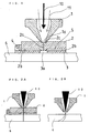
- the laser-beam machining device comprises a cutting nozzle 1 normally used for cutting a machining target and a piercing nozzle 2 used in combination with the cutting nozzle 1 for piercing. Further, a pivotal portion 4 is provided on one end of the piercing nozzle 2, and an underlay 3 is mounted to the piercing nozzle 2 through the pivotal portion 4 so that it can rotate relative to and can be detached from the piercing nozzle 2.
- a spacer 2b is provided in a projected state at four corners of the lower surface (i.e., the surface opposite to the surface brought into engagement with the cutting nozzle 1) of the piercing nozzle 2, so that when the underlay 3 is placed on the side of the piercing nozzle 2, a clearance 5 is formed between the piercing nozzle 2 and the underlay 3, as shown in Fig. 1.
- the underlay 3 is used to prevent scattered dross from adhering to the surface of a machining target 6 at the time of piercing.
- the underlay 3 has a hole 3a in the center.
- the underlay 3 is placed in a manner such that the hole 3a and a hole 2a of the piercing nozzle 2 overlap with each other, in particular, in a manner such that the center of the hole 3a of the underlay 3 is placed in alignment with the center of the hole 2a of the piercing nozzle 2.
- the upper surface of the piercing nozzle 2 has a tapered fitting hole 2c, to which the tip of the cutting nozzle 1 is capable of being fitted.
- the tip of the cutting nozzle 1 has a nozzle hole 1a in the center. Further, the piercing hole 2a is formed to extend from the center of the tapered fitting hole 2c to the lower surface of the piercing nozzle 2.
- a laser beam 10 passes through the nozzle hole 1a at the tip of the cutting nozzle 1, the piercing hole 2a and the hole 3a of the underlay 3 and then reaches the machining target 6.
- the underlay 3 needs to have a size enough to cover the scattering range of the dross caused by the piercing.
- a flat sheet in the shape of a square of 60 mm x 60 mm with a thickness of 3 mm is in use, and its material is the same copper alloy as the piercing nozzle 2.
- the hole 3a formed in the underlay 3 is too large, the scattered dross will adhere to the surface of the machining target 6 at a portion corresponding to the hole 3a, and therefore, it is better to form the hole 3a as small as possible.
- the hole 3a is too small, it will take a longer time disadvantageously to carry out piercing on account of reduction in an area of the part of machining target 6 where the assist gas 11 strikes, and so on.
- the hole 3a of the underlay 3 which is larger than the hole 2a of the piercing nozzle 2 is found by an experiment or the like.
- the hole 3a of the underlay 3 is formed to have a diameter of about 5 mm.
- the clearance 5 between the underlay 3 and the piercing nozzle 2 is set to 3 mm.
- the piercing nozzle 2 Since the piercing nozzle 2 is used for catching scattered dross above the underlay 3, its size is set to be substantially equal to that of the underlay 3.
- the nozzle hole 2a of the piercing nozzle 2 is formed to be smaller in diameter than the nozzle hole 1a of the cutting nozzle 1. If the nozzle hole 2a has a larger diameter, an area of the part of machining target 6 where the assist gas 11 jetted through the nozzle hole 2a strikes is increased and injection speed of the assist gas is reduced, in comparison with the case where the nozzle hole 2a has a smaller diameter with the assist gas 20 supplied under the same pressure.
- the nozzle hole 2a has a smaller diameter, the injection speed is increased and an area of the part of machining target 6 where the assist gas 11 strikes is reduced, in comparison with the case where the nozzle hole 2a has a larger diameter with the assist gas 11 supplied under the same pressure.
- diameter of the nozzle hole 2a is decreased, the force for scattering the dross of the machining target melted in the process of piercing is increased, bringing about quick scattering of the dross caused by the irradiation of the laser beam 10, with the result that the diameter of a hole machined by the piercing decreases and scattered dross decreases in quantity.
- the nozzle hole 2a of the piercing nozzle 2 preferably needs to have a diameter larger than the diameter of converged laser beam 10 and smaller than the nozzle hole 1a of the cutting nozzle 1.
- the nozzle hole 1a of the cutting nozzle 1 has a diameter of 4 mm, and the laser beam 10 has a converged spot diameter of about 0.8 mm
- the nozzle hole 2a of the piercing nozzle 2 is formed to have a diameter of 1.5 mm (larger than 0.8 mm and smaller than 4 mm).
- the length of the hole 2a of the piercing nozzle 2, which has diameter of 1.5 mm, is set to 10 mm. In piercing using this piercing nozzle 2, it is ascertained that it does not matter if the laser beam is reflected from the inner wall of the piercing nozzle 2.
- the cutting nozzle 1 is put above a target position for machining to pierce the machining target 6. Subsequently, the tapered fitting hole 2c of the piercing nozzle 2 is fitted to the tip of the cutting nozzle 1 to combine the cutting nozzle 1 with the piercing nozzle 2 and the underlay 3. Then, the cutting nozzle 1, the piercing nozzle 2 and the underlay 3 are moved down in a combined state toward a piercing position on the machining target 6 such that the underlay 3 is placed on the surface of the machining target 6 as shown in Fig. 1.
- the laser oscillator (not shown) is activated to irradiate the converged laser beam 10 to the machining target 6 through the hole 1a of the cutting nozzle 1, the hole 2a of the piercing nozzle 2 and the hole 3a of the underlay 3 (see Fig. 2A), while the injection of the assist gas 11 to the machining target 6 is carried out through the holes 1a, 2a and 3a.
- the portion of the machining target 6, irradiated by the laser beam 10 starts melting.
- the resultant dross is removed from the machining target 6 by high-speed and high-pressure assist gas 11 jetted through the small-diameter nozzle hole 2a of the piercing nozzle 2.
- the assist gas 11 is turned in a reverse direction after striking against the machining target 6 and is then exhausted from the hole 3a of the underlay 3 to the outside through the clearance 5 between the piercing nozzle 2 and the underlay 3, while the dross carried by the assist gas 11 is cooled down in the course of the passage through the clearance 5 and is then dropped down to the underlay 3, resulting in the adhesion of the dross to the underlay 3.
- the assist gas 11 is jetted at high speed under high pressure to a narrow area of the machining target 6 through the small nozzle hole 2a of the piercing nozzle 2, the dross is removed from the machining target 6 at high speed, so that the laser beam 10 is allowed to melt the inner part of the machining target 6.
- a hole machined by the piercing decreases in diameter, and the scattered dross also decreases in quantity.
- the piercing nozzle 2 and the underlay 3 are removed from the cutting nozzle 1 to start the normal cutting with the cutting nozzle 1 (refer to Fig. 2B).
- the piercing nozzle 2 and the underlay 3, having been removed from the cutting nozzle 1, is put in a ready state for the next piercing after opening the piercing nozzle 2 through the pivotal motion relative to the underlay 3 about the pivotal portion 4 or separating the underlay 3 from the piercing nozzle 2 and then scraping off the adhered dross from the underlay 3.
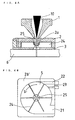
- a cover 2b' is formed at the edge of the piercing nozzle 2, so that when the piercing nozzle 2 is placed opposite to the underlay 3, the cover 2b' serves as a spacer to form a clearance 5 of a predetermined depth between the piercing nozzle 2 and the underlay 3, and also to define the sectional shape of the clearance 5.
- Fig. 3B is a view showing the piercing nozzle 2 of Fig. 3A as viewed from the bottom, after the removal of the underlay 3 placed below the piercing nozzle 2.
- the clearance 5 has a substantially circular sectional shape.
- the cover 2b' has three paths (a path leading to an exhaust port 21, a path leading to an inlet port 22 and a path leading to an injection port 23) which are formed in a parallel arrangement to permit the communication between the clearance 5 and the outside of the piercing nozzle 2.
- the assist gas 11 in the clearance 5 is exhausted to the outside through the exhaust port 21.
- a fluid such as compressed air is supplied from the outside into the clearance 5 through the inlet port 22.
- Oil, a soap solution or a surface active solution is jetted or sprayed from the outside into the clearance 5 through the injection port 23.
- the compressed air supplied into the clearance 5 through the inlet port 22 flows along the inner surface of the clearance 5 of the circular sectional shape to form a swirl flow and is then exhausted through the exhaust port 21.
- the dross scattered by the assist gas 11 is cooled down by the compressed air and is then exhausted through the exhaust port 21. Since the dross is cooled down by the compressed air before being exhausted through the exhaust port 21 as described above, the quantity of dross adhered to the surface of the underlay 3, which is exhausted through the exhaust port 21 and then dropped down to the underlay 3, is decreased.
- a fluid (gas or liquid) other than the compressed air may be supplied through the inlet port 22.
- the scattered dross is covered and then cooled down with oil, soap solution or surface active solution which has been jetted into the clearance 5 through the injection port 23, the dross dropped down to the underlay 3 after having been cooled down is hardly adhered to the underlay 3, and as a result, is exhausted through the exhaust port 21 together with the compressed air supplied through the inlet port 22.
- the piercing nozzle 2 and the underlay 3 may be used for a long time without being cared for. Further, even if the dross is adhered to the underlay 3, it is possible to easily remove the adhered dross from the underlay 3 by enclosing the adhered dross with the oil, the soap solution or the surface active solution.
- the laser-beam machining device may carry out the piercing continuously without frequent operation for removing the dross.
- the laser-beam machining device according to the third embodiment is equivalent to a laser-beam machining device having a plurality of blades 24 (six blades in the embodiment shown in Fig. 4B) provided in a rotatable state in the clearance 5 of the laser-beam machining device according to the second embodiment.
- These blades 24 are mounted on the piercing nozzle 2 at the center portion thereof (a portion surrounding the nozzle hole 2a) through a ball bearing 25 so that they can rotate. More specifically, as shown in Fig. 4A, a cylindrical projection projecting toward the clearance 5 is formed in the center of the piercing nozzle 2, and an inner race of the ball bearing 25 is fixed to the projection. On the other hand, these six blades 24 are fixed to the outer race of the ball bearing 25.
- These blades 24 are rotated by the compressed air supplied into the clearance 5 through the inlet port 22 in the course of piercing.
- dross caused by irradiation of the laser beam 10 and then scattered by the assist gas 11 is carried toward the exhaust port 21 together with the assist gas through the rotation of the blades 24 while being cooled down by the compressed air and is then exhausted through the exhaust port 21.
- the rotating blades 24 carry the dross toward the exhaust port 21 after having scraped off from the underlay 3, and the dross is exhausted through the exhaust port 21.
- the dross when carrying out piercing using the laser-beam machining device according to the third embodiment, since the dross is forcibly exhausted by the blades 24, the dross can not accumulate in the clearance 5, so that it is possible to carry out piercing continuously. Further, since the dross is not allowed to adhere and accumulate on the underlay 3, there is no need to frequently clean the underlay 3.
- the underlay 3 and the piercing nozzle 2 are connected together pivotally through the pivotal means (the pivotal portion 4).
- a fixing means such as a set screw is used to connect the underlay 3 and the piercing nozzle 2 together.
- the compressed air is supplied into the clearance 5 through the inlet port 22.
- fluid such as compressed air need not be supplied through the inlet port 22, or the inlet port 22 for supplying the fluid need not be formed in the cover 2b' of the piercing nozzle 2.
- the assist gas 11 jetted at high speed under high pressure toward the machining target 6 is turned in the reverse direction after striking against the machining target 6 and then flows into the clearance 5 between the piercing nozzle 2 and the underlay 3, while the assist gas 11 in the clearance 5 forms a swirl flow and is then exhausted to the outside through the exhaust port 21 serving as the only outlet.
- the swirl flow of the assist gas 11 causes the rotation of the blades 24.
- connection of the piercing nozzle 2 to the cutting nozzle 1 is carried out only by fitting the tip of the cutting nozzle 1 to the tapered fitting hole 2a of the piercing nozzle 2 without any special attaching mechanism used.
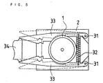
- FIG. 5 is a view of the cutting nozzle 1 mounted with the piercing nozzle 2 though the attaching mechanism, as viewed from the top. It should be noted that the piercing nozzle 2 mounted with the attaching mechanism as will be described later and the underlay 3 connected to this piercing nozzle 2 have the same structure as those of the laser-beam machining device according to the first, second and third embodiments.
- the outer surface of the cutting nozzle 1 has a groove to which a pair of clips 33 (which will be described later) constituting a mounting mechanism are fitted.
- a pair of shafts 31 are provided in a projected state on one side of the upper surface (i.e., the surface on the side opposite to the cutting nozzle 1) of the piercing nozzle 2, and the bases of the clips 33 are respectively mounted to the shafts 31 in a pivotal state. Further, a spring 32 is provided between these two clips 33, and these two clips 33 are energized to come close to each other by means of the spring 32.
- Each clip 33 has a tapered end, and a distance between the inner edge of one clip 33 and the inner edge of the other clip 33 gradually widens toward the ends of the clips. Then, when a removing member 34 is pressed against the ends of the clips 33 and is then pushed toward the cutting nozzle 1, the pair of clips 33 are expanded against the force of the spring 32 as shown by a broken line of Fig. 5.
- the tip of the cutting nozzle 1 is fitted to the tapered fitting hole 2c of the piercing nozzle 2 with the clips 33 expanded by the removing member 34, and thereafter, the removing member 34 is removed from the clips.
- the energizing force of the spring 32 acts on the pair of clips 32 to cause them to come close to each other, so that these clips 32 are kept fitted to the groove formed in the cutting nozzle 1.
- the cutting nozzle 1 and the combination of the piercing nozzle 2 with the underlay 3 are connected together in one body through the attaching mechanism.
- the removing member 34 is firstly pushed against the ends of the clips 33 to expand the clips 33 as shown by the broken line of Fig. 5. Thereupon, since the clips 33 are slipped out of the groove formed on the cutting nozzle 1, the piercing nozzle 2 and the underlay 3 connected thereto can be removed from the cutting nozzle 1.
- the combination of the piercing nozzle 2 and the underlay 3 can be mounted to or detached from the cutting nozzle 1.
- the combination of the piercing nozzle 2 and the underlay 3 may be kept always mounted to the cutting nozzle 1 or a machining head, for mounting the cutting nozzle 1 in a manner such that the combination can move relative to the cutting nozzle 1.
- a mounting tool (not shown) is attached to the laser-beam machining head which mounts the cutting nozzle 1 so that it can move relative to the cutting nozzle 1, and then the combination of the piercing nozzle 2 and the underlay 3 is mounted to the mounting tool.
- the mounting tool is operated to selectively place the combination of the piercing nozzle 2 and the underlay 3 at a position where the piercing nozzle 2 comes into engagement with the cutting nozzle 1 (during piercing works) and a position where the piercing nozzle 2 is placed distant from the cutting nozzle 1 (during normal cutting).
- the following table 1 shows the results of experiment made under the conditions that a carbon dioxide gas laser oscillator of 3kW was used to carry out piercing for a mild steel sheet having a thickness of 25 mm through the injection of oxygen assist gas.
- Piercing based on pulse output Piercing by means of cutting nozzle based on continuous output
- Piercing according to the invention (based on continuous output)
- (a) (b) Nozzle hole diameter (mm) 3.0 1.5 3.0 1.5
- Assist gas pressure (kgf/cm 2 ) 0.3 1.0 0.3 1.0 Oscillator power (kW) 3 3 3 3 3 3
- the piercing in the experiment (b) was carried out under the same conditions as the experiment (a), except that a nozzle having a hole diameter of 1.5 mm was used, and the pressure of the assist gas was set to 1.0 kgf/cm 2 . As a result, a piercing hole having a diameter of 1.5 mm was produced in 25 seconds.
- the piercing was carried out under the conditions where a cutting nozzle having a hole diameter of 3.0 mm was used, the pressure of the assist gas was set to 0.3 kgf/cm 2 and the power of the laser oscillator was set to 3kW at its maximum based on continuous output. As a result, the piercing was completed in 3 seconds, while the diameter of a machined hole was as large as 20 to 30 mm.
- the piercing was carried out under the conditions that a nozzle having a hole diameter of 1.5 mm was used, the pressure of the assist gas was set to 1.0 kgf/cm 2 and the power of the laser oscillator was set to 3kW at its maximum based on a continuous output. As a result, a piercing hole having a diameter of 6 mm was produced in 0.8 seconds.
- the piercing according to the invention enables a hole having a smaller diameter to be formed in a shorter machining time, as compared with piercing by means of the cutting nozzle.
- the piercing according to the invention when the piercing according to the invention is compared with the conventional piercing based on pulse output, it is found that a hole of a smaller diameter can be machined by the conventional piercing based on pulse output, while the machining time can be remarkably shortened by the piercing according to the invention.
- the fact that the machining time for piercing is remarkably as short as 0.8 seconds in the case of the invention as shown in the table 1 results in that the time required for conduction of heat, which is produced when the machining target at the piercing position is melted by the laser beam 10, to the other area is remarkably shortened. For that reason, it is supposed that a piercing hole having a diameter of 6 mm, not so large, can be formed.
- the table 2 shows the results of the experiment applied to a mild steel sheet (SS400 material) having a thickness of 19 mm by the use of a carbon dioxide gas laser oscillator of 3kW.
- the table 3 shows the results of the experiment applied to a soft steel sheet (SS400 material) having a thickness of 25 mm by the use of a carbon dioxide gas laser oscillator of 6kW.
- the machining was carried out with the assist gas pressure of 1.0 kgf/cm 2 and based on continuous output of laser oscillator. Since the machining time for piercing and the hole diameter are subject to variation, the numerical values in the tables 2 and 3 are given as their mean values.
- the nozzle for piercing should have a hole diameter larger than the diameter of converged laser beam but not exceeding about 2.5 mm. Further, as is apparent from the tables 2 and 3, when the nozzle having a hole diameter in the range from 1.5 to 2.5 mm is in use, the machining time for piercing is below 1 second, and the diameter of a machined hole is in the range from 6 to 10 mm.
- the machining time for piercing is largely subject to variation from below 1 ( ⁇ 1) to 3 seconds (the diameter of a machined hole is also subject to variation from 6 to 4 mm).
- a nozzle having a hole diameter of about 1.5 mm is suitable for the piercing.
- piercing may be carried out only by using the piercing nozzle without the need for an underlay.
- the piercing in this case inevitably has a defect in that the dross is adhered to the surface of the machining target, while there is an advantage in that the piercing may be carried out for a short period of time.
- dross is small in quantity, with the result that adhesion of the dross to the machining target is advantageously small.
- the piercing may be carried out only by using the underlay 3 without the need for the piercing nozzle 2.
- the piercing by using only the underlay may be applied to the conventional piercing to advantageously prevent the dross from adhering to the surface of the machining target.
- a laser-beam machining device having an automatic nozzle exchanging device capable of automatically exchanging a nozzle mounted to the laser-beam machining head may be used for the piercing.
- a cutting nozzle and a piercing nozzle are placed in advance in the automatic nozzle exchanging device.
- the piercing nozzle is automatically mounted to the laser-beam machining head according to a command from a control device such as a numerical control unit operated by the input of an NC program.
- the cutting nozzle is automatically mounted to the laser-beam machining head.
- piercing may be carried out for a short period of time to machine a hole having a small diameter, and the quantity of scattered dross is decreased.
- the underlay may be used to catch the scattered dross to prevent the dross from adhering to the surface of the machining target. Further, the scattered dross dropped down to the underlay may be forcibly removed to enable continuous piercing.
Landscapes
- Engineering & Computer Science (AREA)
- Physics & Mathematics (AREA)
- Optics & Photonics (AREA)
- Plasma & Fusion (AREA)
- Mechanical Engineering (AREA)
- Laser Beam Processing (AREA)
Applications Claiming Priority (2)
| Application Number | Priority Date | Filing Date | Title |
|---|---|---|---|
| JP31834498 | 1998-10-21 | ||
| JP31834498A JP3198095B2 (ja) | 1998-10-21 | 1998-10-21 | レーザ加工装置 |
Publications (2)
| Publication Number | Publication Date |
|---|---|
| EP1005945A2 true EP1005945A2 (de) | 2000-06-07 |
| EP1005945A3 EP1005945A3 (de) | 2004-05-12 |
Family
ID=18098121
Family Applications (1)
| Application Number | Title | Priority Date | Filing Date |
|---|---|---|---|
| EP99307625A Withdrawn EP1005945A3 (de) | 1998-10-21 | 1999-09-28 | Laserbearbeitungsverfahren, Laserbearbeitungsvorrichtung und Hilfsgerät zum Bohren |
Country Status (3)
| Country | Link |
|---|---|
| US (2) | US6335507B1 (de) |
| EP (1) | EP1005945A3 (de) |
| JP (1) | JP3198095B2 (de) |
Cited By (2)
| Publication number | Priority date | Publication date | Assignee | Title |
|---|---|---|---|---|
| EP1145796A1 (de) * | 2000-04-10 | 2001-10-17 | Tanaka Engineering Works, Ltd. | Lochvorrichtung für Laserschneidgerät |
| DE102006040784B4 (de) * | 2005-09-07 | 2015-06-25 | Disco Corp. | Laserstrahlbearbeitungsmaschine |
Families Citing this family (14)
| Publication number | Priority date | Publication date | Assignee | Title |
|---|---|---|---|---|
| JP3198095B2 (ja) * | 1998-10-21 | 2001-08-13 | ファナック株式会社 | レーザ加工装置 |
| JP3714931B2 (ja) * | 2002-12-12 | 2005-11-09 | コマツ産機株式会社 | プラズマ切断方法およびその装置 |
| US6969822B2 (en) * | 2003-05-13 | 2005-11-29 | Hewlett-Packard Development Company, L.P. | Laser micromachining systems |
| US7619180B2 (en) * | 2003-06-25 | 2009-11-17 | Reinhard Diem | Laser head of a laser beam processing machine comprising alternating nozzles |
| DE50312360D1 (de) * | 2003-08-09 | 2010-03-11 | Trumpf Werkzeugmaschinen Gmbh | Laserbearbeitungsdüsenkupplung |
| DE102004041273A1 (de) * | 2004-08-23 | 2006-03-02 | Alstom Technology Ltd | Bohrvorrichtung |
| JP4720380B2 (ja) * | 2005-08-31 | 2011-07-13 | 澁谷工業株式会社 | レーザ加工装置 |
| EP2189236B1 (de) * | 2008-11-21 | 2012-06-20 | Synova S.A. | Verfahren und Vorrichtung zur Verbesserung der Zuverlässigkeit einer maschinellen Bearbeitung |
| US8829388B2 (en) * | 2011-07-29 | 2014-09-09 | Ipg Photonics Corporation | Method for contactless laser welding and apparatus |
| CN105108337B (zh) * | 2015-09-01 | 2017-07-28 | 广东工业大学 | 一种水轮机叶片裂纹修复方法 |
| KR101886822B1 (ko) * | 2016-12-07 | 2018-08-08 | 홍준화 | 흡음형 방음판 보수 공법 및 흡음형 방음판 보수 시스템 |
| JP6577110B2 (ja) * | 2017-10-06 | 2019-09-18 | 株式会社アマダホールディングス | レーザ加工方法及びレーザ加工装置 |
| CN114871602B (zh) * | 2022-04-19 | 2024-08-30 | 济南金威刻激光科技股份有限公司 | 一种用于全能型激光切割机的管材支撑装置 |
| US12472580B2 (en) * | 2022-06-01 | 2025-11-18 | Caterpillar Inc. | Laser handheld trimming and welding device |
Family Cites Families (25)
| Publication number | Priority date | Publication date | Assignee | Title |
|---|---|---|---|---|
| US3597578A (en) * | 1967-03-16 | 1971-08-03 | Nat Res Dev | Thermal cutting apparatus and method |
| JPS62158593A (ja) | 1985-12-28 | 1987-07-14 | Murata Mach Ltd | レ−ザ加工機 |
| JPS6352792A (ja) | 1986-08-21 | 1988-03-05 | Mitsubishi Electric Corp | レ−ザ加工装置 |
| JPH02284780A (ja) | 1989-04-27 | 1990-11-22 | Amada Co Ltd | レーザ加工に於けるピアス成形方法及びレーザビームノズル装置 |
| JP2618730B2 (ja) * | 1990-01-29 | 1997-06-11 | 松下電器産業株式会社 | レーザ加工方法およびレーザ加工装置 |
| JP2856854B2 (ja) | 1990-07-11 | 1999-02-10 | 日本放送協会 | 固体撮像装置 |
| JP2875626B2 (ja) | 1990-11-30 | 1999-03-31 | 小池酸素工業株式会社 | レーザーピアシング方法 |
| JPH05185261A (ja) | 1991-03-07 | 1993-07-27 | Fanuc Ltd | レーザ加工機のピアシング制御方法 |
| JPH05111783A (ja) * | 1991-10-19 | 1993-05-07 | Fanuc Ltd | レーザ加工における穴明け加工方法 |
| TW270907B (de) * | 1992-10-23 | 1996-02-21 | Mitsubishi Electric Machine | |
| JP3179892B2 (ja) | 1992-10-28 | 2001-06-25 | 日立建機株式会社 | レーザ加工装置並びにレーザ加工方法 |
| JP2720744B2 (ja) * | 1992-12-28 | 1998-03-04 | 三菱電機株式会社 | レーザ加工機 |
| JPH07223084A (ja) * | 1994-02-10 | 1995-08-22 | Fanuc Ltd | レーザ加工装置 |
| JPH09136177A (ja) | 1995-11-10 | 1997-05-27 | Fuji Electric Co Ltd | レーザ加工装置 |
| JP3526998B2 (ja) | 1996-01-18 | 2004-05-17 | 株式会社アマダ | 表面被覆材のレーザ加工方法および同加工方法に使用するレーザ加工ヘッド |
| JPH09271980A (ja) | 1996-04-08 | 1997-10-21 | Amada Co Ltd | レーザ加工機におけるスパッタ等吸引方法及びその装置 |
| JPH10113784A (ja) | 1996-10-08 | 1998-05-06 | Amada Co Ltd | レーザ加工装置 |
| JPH10137970A (ja) | 1996-11-11 | 1998-05-26 | Amada Eng Center:Kk | 熱加工装置およびその装置に用いる加工ヘッド |
| JPH10225787A (ja) | 1997-02-13 | 1998-08-25 | Tanaka Seisakusho Kk | レーザ切断装置およびレーザ切断方法 |
| JP3749349B2 (ja) | 1997-05-08 | 2006-02-22 | 株式会社アマダ | レーザ加工方法及びレーザ加工機 |
| JPH10318344A (ja) | 1997-05-20 | 1998-12-04 | Maezawa Kiyuusou Kogyo Kk | 多条螺子によるピッチ進退機構及び分水栓 |
| JP3751728B2 (ja) | 1997-11-07 | 2006-03-01 | 小池酸素工業株式会社 | ピアシング用のノズル |
| JPH11314189A (ja) | 1998-04-28 | 1999-11-16 | Amada Co Ltd | レーザ加工方法およびその方法に用いるレーザ加工ヘッド |
| JP4162772B2 (ja) * | 1998-09-09 | 2008-10-08 | 日酸Tanaka株式会社 | レーザピアシング方法およびレーザ切断装置 |
| JP3198095B2 (ja) * | 1998-10-21 | 2001-08-13 | ファナック株式会社 | レーザ加工装置 |
-
1998
- 1998-10-21 JP JP31834498A patent/JP3198095B2/ja not_active Expired - Fee Related
-
1999
- 1999-09-23 US US09/401,942 patent/US6335507B1/en not_active Expired - Fee Related
- 1999-09-28 EP EP99307625A patent/EP1005945A3/de not_active Withdrawn
-
2001
- 2001-11-15 US US09/987,602 patent/US6608279B2/en not_active Expired - Fee Related
Cited By (3)
| Publication number | Priority date | Publication date | Assignee | Title |
|---|---|---|---|---|
| EP1145796A1 (de) * | 2000-04-10 | 2001-10-17 | Tanaka Engineering Works, Ltd. | Lochvorrichtung für Laserschneidgerät |
| US6492617B2 (en) | 2000-04-10 | 2002-12-10 | Tanaka Engineering Works, Ltd. | Piercing device for laser cutter |
| DE102006040784B4 (de) * | 2005-09-07 | 2015-06-25 | Disco Corp. | Laserstrahlbearbeitungsmaschine |
Also Published As
| Publication number | Publication date |
|---|---|
| US6608279B2 (en) | 2003-08-19 |
| JP2000126889A (ja) | 2000-05-09 |
| US6335507B1 (en) | 2002-01-01 |
| EP1005945A3 (de) | 2004-05-12 |
| US20020053556A1 (en) | 2002-05-09 |
| JP3198095B2 (ja) | 2001-08-13 |
Similar Documents
| Publication | Publication Date | Title |
|---|---|---|
| US6335507B1 (en) | Laser-beam machining method, laser-beam machining device and auxiliary tool for piercing | |
| JP3056723B1 (ja) | レ―ザ加工装置 | |
| JP5276699B2 (ja) | ピアシングを行うレーザ加工方法及びレーザ加工装置 | |
| US9956648B2 (en) | Piercing metal workpieces by a laser beam | |
| JP2007196373A (ja) | フライス及びレーザで材料を機械加工するための組み合わせ装置 | |
| JP3749349B2 (ja) | レーザ加工方法及びレーザ加工機 | |
| JPH0639571A (ja) | レーザ切断方法および装置 | |
| JP2009297724A (ja) | ろう付けワイヤの切断方法 | |
| JPH11314189A (ja) | レーザ加工方法およびその方法に用いるレーザ加工ヘッド | |
| JP2008515643A (ja) | 106〜109Wcm−2の範囲の放射照度と、10〜50kHzの範囲の繰返し率とを有するレーザを使用する硬質材料の加工処理装置及び加工処理方法 | |
| KR101169981B1 (ko) | 레이저 가공 방법 및 오일링용 선재 | |
| KR20170043252A (ko) | 버 제거가 가능한 마찰교반 용접장치 | |
| JPH0947888A (ja) | レーザピアシング方法およびその装置 | |
| JPH11123581A (ja) | レーザ加工機における消火方法およびその装置 | |
| JP2875626B2 (ja) | レーザーピアシング方法 | |
| JPS5964191A (ja) | レ−ザ加工装置 | |
| JPH115179A (ja) | 摩擦溶接方法 | |
| JP2005046849A (ja) | レーザ加工方法およびレーザ加工装置 | |
| KR100507499B1 (ko) | 브레이징 접합용 레이저 헤드장치 | |
| JPH10323781A (ja) | レーザ加工方法 | |
| JPS609606A (ja) | レ−ザ切「くず」切断バイト | |
| JP2718224B2 (ja) | レーザ切断方法 | |
| JP2006346716A (ja) | レーザ加工方法 | |
| JPH01228695A (ja) | レーザ加工方法 | |
| JP4566840B2 (ja) | 反射鏡の穿孔方法 |
Legal Events
| Date | Code | Title | Description |
|---|---|---|---|
| PUAI | Public reference made under article 153(3) epc to a published international application that has entered the european phase |
Free format text: ORIGINAL CODE: 0009012 |
|
| AK | Designated contracting states |
Kind code of ref document: A2 Designated state(s): AT BE CH CY DE DK ES FI FR GB GR IE IT LI LU MC NL PT SE |
|
| AX | Request for extension of the european patent |
Free format text: AL;LT;LV;MK;RO;SI |
|
| PUAL | Search report despatched |
Free format text: ORIGINAL CODE: 0009013 |
|
| AK | Designated contracting states |
Kind code of ref document: A3 Designated state(s): AT BE CH CY DE DK ES FI FR GB GR IE IT LI LU MC NL PT SE |
|
| AX | Request for extension of the european patent |
Extension state: AL LT LV MK RO SI |
|
| RIC1 | Information provided on ipc code assigned before grant |
Ipc: 7B 23K 26/38 B Ipc: 7B 23K 26/14 B Ipc: 7B 23K 26/00 A |
|
| 17P | Request for examination filed |
Effective date: 20040806 |
|
| AKX | Designation fees paid |
Designated state(s): DE |
|
| STAA | Information on the status of an ep patent application or granted ep patent |
Free format text: STATUS: THE APPLICATION IS DEEMED TO BE WITHDRAWN |
|
| 18D | Application deemed to be withdrawn |
Effective date: 20060328 |