EP1005960A2 - Ein Schall- und Staub geschützter Bohrhammer - Google Patents
Ein Schall- und Staub geschützter Bohrhammer Download PDFInfo
- Publication number
- EP1005960A2 EP1005960A2 EP99118866A EP99118866A EP1005960A2 EP 1005960 A2 EP1005960 A2 EP 1005960A2 EP 99118866 A EP99118866 A EP 99118866A EP 99118866 A EP99118866 A EP 99118866A EP 1005960 A2 EP1005960 A2 EP 1005960A2
- Authority
- EP
- European Patent Office
- Prior art keywords
- outer housing
- breaker
- main body
- space
- further comprised
- Prior art date
- Legal status (The legal status is an assumption and is not a legal conclusion. Google has not performed a legal analysis and makes no representation as to the accuracy of the status listed.)
- Withdrawn
Links
Images




Classifications
-
- B—PERFORMING OPERATIONS; TRANSPORTING
- B25—HAND TOOLS; PORTABLE POWER-DRIVEN TOOLS; MANIPULATORS
- B25D—PERCUSSIVE TOOLS
- B25D17/00—Details of, or accessories for, portable power-driven percussive tools
- B25D17/11—Arrangements of noise-damping means
Definitions
- the present invention relates to a sound and vibration proof breaker, and more particularly to a sound proof apparatus for absorbing and reducing both noise and vibration generated by the breaker while minimizing the scattering of debris and dust generated by the breaker from being scattered.
- noise and vibration proof apparatus are used in a breaker such as a pneumatic or hydraulic jack hammer.
- an absorber attached to a portion of the breaker is used to attenuate noise and vibration.
- a reciprocating drive piston that is powered by hydraulic liquid in main body of the breaker repeatedly drives a hammer piston to impact upon and to return from a tool grasped by a front head portion of the main body in the breaker.
- noise and vibration generated from the breaker can be earsplitting in intensity and may cause users of the breaker to be damaged psychologically and physically.
- various types of absorbers have been used in efforts to reduce the noise and vibration.
- German publication number DE 4,030,126A for a Hydraulic Road Drill Casing discloses a hydraulic drill totally enclosed in a sandwich casing formed from an outer shell and inner shell.
- a filler such as fine-grained sand or other relatively incompressible damping material, is filled in a space between the outer shell and inner shell of the sandwich casing.
- Plastic pads provide radial and end support between the hydraulic drill and casing.
- the filler such as fine-grained sand or other relatively incompressible damping material, however is easily crashed by repeated vibration.
- the filler accumulates in the bottom side of the sandwich casing, and the upper portion of the sandwich casing can be vacated. Therefore, I have noticed that this apparatus has several critical defects and that the filler can not absorb and reduce the vibration and the noise effectively during operation of the hydraulic drill.
- U.S. Patent 4,838,363 for a Rock-Breaking Apparatus issued to MacOnochie discloses an annulus made from a piece of shock-absorbing material, such as a relatively dense plastic or elastomeric material capable of deformation and restoration of its original shape after deformation, that is located within guide column in order to minimizing the effect of the weight of the tool on the other part of the rock-breaking apparatus.
- U.S. Patent 4,440,237 for a Pavement Breaker issued to Casperovich discloses a compression chamber and a pair of expansion chambers used for reducing the shock effect transmitted by the reciprocating piston to housing.
- U.S. Patent 3,559,753 for a Percussion Tool issued to Meri discloses a percussion tool such as an air hammer having a spring absorbing the shock of the downward stroke of the scissor.
- U.S. Patent 3,168,324 for a Chuck issued to Kennell discloses a pneumatic percussion tool having a cushion to reduce the shock of the floor from the chuck striking the cushion. I have noticed that the embodiments disclosed by these references does not absorb and reduce the vibration and noise effectively because the absorber is partially located on an operational part of the machine.
- U.S. Patent 4,382,475 for a Hydraulic Hammer Apparatus issued to Suzuki discloses a hydraulic hammer apparatus including a fluid chamber filled with fluid for preventing noise made by the collision from being externally propagated the noise is absorbed by the fluid, and this prevents the heavy vibration made by the collision from being emitted.
- U.S. Patent 2,558,165 for a Cushioning Device For Rock Drill issued to Anderson discloses rock drills having a cavity filled with fluid under pressure in order to absorb any shocks applied to the chuck by the drill steel. I have noticed that the embodiments taught by these references do not absorb and reduce the vibration and noise effectively because the fluid fills only a portion of the circumferential surface of the machine.
- U.S Patent 3,735,824 for an Arrangement In and Relating To a Chiselling Hammer or Similar Percussion Machine issued to Astrom discloses a motor housing made of a damping material with a passage in the machine housing. A quantity of dust produced at the tip of the tool is collected and removed through the passage.
- U.S. Patent 3,223,181 for a Vibrationless Air Hammer Assembly issued to Price is equipped with air exhaust ports. Air discharged from the port of the air motor into the casing is discharged downwardly through the air exhaust ports, in an effort to reduce the noise that accompanies the discharge of air from the port. I have found however, that these embodiments do not prevent the debris and dust from being scattered.
- An upper absorber such as polyurethane or nitrile-budadiene rubber
- a lower absorber such as polyurethane or nitrile-budadiene rubber
- Side absorbers such as polyurethane or nitrile-budadiene rubber, are inserted into the space to maintain a distance between the main body and the outer housing and to maintain the shape of the space.
- the combination of the water, the upper absorber, the lower absorber, and the side absorbers significantly absorb and reduce the vibration and noise generated by the breaker during operation.
- a fluid hole is formed on the outer housing and is connected to a fluid hose, and water is supplied into the space through the fluid hole and the fluid hose.
- a plurality of hydraulic holes are formed on the outer housing, and hydraulic tubes are connected to the hydraulic inlet and outlet formed on the main body through the hydraulic hole.
- a plurality of holes form nozzles in the outer housing near the impact tool, and the water is ejected to the end of the impact tool through the nozzles. Water may be ejected through a passage formed on the absorber and the nozzle hole or only through the nozzles. Water is supplied the space through the fluid hose during operation of the breaker.
- a main body 1 of breaker 200 includes a cap portion 11, a cylinder and valve chamber having a valve region 12 and a piston cylinder 13, and a front head 15.
- Impact tool 14 protrudes from front head 15 and is reciprocated by a hammer of front head 15 which is driven by movement of cylindrical piston 13.
- Hydraulic inlet 121 and outlet 122 are connected to valve 12 within body 1 to drive piston cylinder 13.
- a connecting plate 42 for bracket 4 is connected to a head connector 21 of outer housing 2 to support outer housing 2 after main body 1 and impact tool 14 are inserted into the inside of outer housing 2 with a space between main body 1 and outer housing 2.
- bracket 4 may be connected to a portion extending from cap 11 of main body 1. In this instance, bracket 4 can be connected to or fixed on both outer housing 2 and main body 1.
- Outer housing 2 includes a front cover 22 having a first guide bole 23. Impact tool 14 of the breaker moves reciprocally through first guide bole 23 of front cover 22 during operation of the breaker
- An upper absorber 35 such as polyurethane or nitrile-budadiene rubber, is disposed and inserted between cap 11 of main body 1 to seal the space 3 and connecting plate 42 of bracket 4 after main body is inserted into the inside of outer housing 2.
- upper absorber 35 can be disposed between cap portion 11 and head connector 21 of outer housing 2.
- Side absorbers 31, 32, 33 and 34 shown in Fig. 1,36,37,38 and 39 shown in Fig. 3, are attached to side surface of main body 1 and disposed between main body 1 and outer housing 2.
- Upper absorber 35, lower absorber 6, and side absorbers 31, 32, 33, 34 support main body 1 against outer housing 2 and absorb vibration and noise generated by the main body 1 of breaker 200 while upper absorber 35 and lower absorber 6 seal space 3.
- a fluid hole 23 is formed on outer housing 2.
- Fluid bolt 24 having a central hole is fixed around fluid hole 23 of outer housing 2, and a collar 71 is connected to bolt 24.
- Fluid hose 7 is connected to the collar 71, thereby fluid hole, central hole of bolt 24, collar 71, and fluid hose 7 form a passageway for liquid, such as water, to be supplied into space 3.
- Space 3 between outer housing 2 and main body 1 is filled with water supplied through fluid hose 7, collar 71, fluid bolt 24, and fluid hole 23 of outer housing 2.
- Main body 1 and outer housing are properly scaled.
- Hydraulic inlet 121 and outlet 122 formed on main body 1 are connected to hydraulic hoses (not shown) through hydraulic holes in outer housing 2.
- the water that fills space 3 between outer housing 2 and main body 1 absorbs and reduces vibration and noise generated by main body 1.
- the quantity of water that fills space 3 is maintained by continuously supplying water into space 3 through fluid hose 7 connected to outer housing 2.
- Lower absorber 6 may be constructed to include a plurality of radial passages 61, an annular passage 62, and second guide hole 63.
- a plurality of discrete holes form an array of a plurality of nozzles 86 on front cover 22 of outer housing 2.
- Water that fills space 3 passes sequentially through radial passages 61 and annular passage 62 and is finally ejected through nozzles 86.
- the water can be ejected directly through nozzles 86 without passing through the passages formed on the absorber if the nozzles are formed through an area of the outer housing 2 that is not covered by absorber 6.
- the ejected water tends to stream around the tip of impact tool 14.
- impact tool 14 breaks up a solid object, such pavement, rock or other rigid material, and scatters debris and dust
- the scattered debris and dust from around the tip of impact tool 14 can be reduced water significantly by the water ejected via nozzles 86.
- the quantity of water that fills space 3 is maintained by supplying water to space 3 through fluid hose 7 connected to outer housing 2.
- Fig. 5 and Fig. 6 show another preferred embodiment of lower absorber 8 suitable for use in the practice of the present invention.
- Lower absorber 8 is disposed both between bottom side of front head portion 15 and front cover 22 of outer housing 2 and between side surface of front head portion 15 and sidewall of outer housing 2.
- Lower absorber 8 extends to lower portion of space 3.
- Vertical passages 84 are formed on the lower absorber 8 and are connected to a annual passage 82 through corresponding radial passages 81. Water passes from space 3 through vertical passages 84, radial passages 81, and annular passage 82 and finally is ejected through nozzles 86 formed on front cover 22 of outer housing 2.
- Fig. 3 shows the hydraulic inlet and outlet of Fig.1.
- Adapter 92 is fixed to main body 1.
- Hydraulic hose 91 is connected to adapter 92 while seal packing 93, such as rubber, for sealing and absorbing vibration generated by main body 1 is inserted between hydraulic hole 135 of outer housing 2 and hydraulic hose 91.
- Hydraulic inlet 121 and outlet 122 have the same structure as adapter 92, hydraulic hose 91, and seal packing 93.
- Two hydraulic holes 135 are formed on outer housing 2 and are used for hydraulic inlet 121 and outlet 122.
- Head connector 21 of outer housing 2 is connected to connecting plate 42 by bolts 43A and nuts 41A.
- a seal washer is inserted between bolt 43A of head connector 21 and nut 41A of connecting plate 42.
- An extension plate 26 extended from or fixed to cap portion 11 of main body 1 is connected to connecting plate 42 by bolts 43B and nuts 41B.
- a seal washer is inserted between nut 41B of connecting plate 42 and bolt 43B of extension plate 26.
- Upper absorber 35 is inserted between extension plate 26 and connecting plate 42 to seal space 3.
- a gasket for sealing and packing may be inserted between extension plate 26 of main body 1 and bead connector 21 of outer housing 2 and between connecting plate 42 of frame 4 and head connector 21 of outer housing 2
- Upper absorber 35 has a lot of bolt holes accommodating bolts 43B of extension plate 26 located inside of outer housing and bolts located on cap portion 11 of main body 1. Head connector 21 is fixed and welded to the outer housing and is connected to the connecting plate of bracket 4 by using bolts 43A and nuts 41A. In the constitution of an alternate embodiment, only bolts shown outside of outer housing 2 may be used to connect outer portion 28 of head connector 21 of outer housing 2 to outer portion 27 of connecting plate 42 of bracket 4. In this alternative embodiment, head connector 21 of outer housing 2 has opening 29 (as shown in Fig. 1) to connect the extended portion of main body 1 to bracket 4 or to allow upper absorber 35 to be located between connecting plate 42 of bracket 4 and cap portion 11 of main body 1. Upper absorber 35 may have holes to accommodate only bolts of cap portion 11 of main body 1 as shown in Fig. 1.
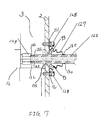
- Adapters 123 and 124 for each hydraulic inlet 121 and outlet 122 are fixed and welded to valve portion 12 of main body 1. Threaded screws structure 132 are formed on adapters 124. Hydraulic hose 125 is inserted and attached by threading to structure 132 through hydraulic hole 135 while the female threads formed on the inside of front end 133 of hydraulic hose 125 is connected to the male threaded portion formed on outer surface of screw structure 123. Seal packing 93 is disposed to form a leakproof junction between hydraulic hole 135 and hydraulic hose 125. Before seal packing 93 is inserted into hydraulic hole 135, one end of seal cover 127 is inserted between seal packing 93 and outer housing 2.
- seal cover 127 is fitted to both outer housing 2 and hydraulic hose 125.
- Outer end 131 of seal cover 127 is clamped between outer housing 2 and seal bolt 128.
- Seal bolt 128 is threaded into outer housing 2.
- Inner end 130 of seal cover 127 is fitted around of the periphery hydraulic hose 125. Together, packing seal 93 and seal cover 127 prevent water from leaking.
- nipple 24 is welded onto the exterior surface 25 of outer housing 2 while central hole of nipple 24 and fluid hole 23 form a passage through the wall of outer housing 2.
- Collar 71 is connected to nipple 24, and fluid hose 7 is connected to collar 71.
- Collar 71 has one end connected to nipple 24 and the other end connected to fluid hose 7.
- Water is supplied from outside of main body 1 to the space 3 formed between outer housing 2 and main body 1 of breaker through fluid hose 7, collar 71, nipple 24, and fluid hole 23.
- the supply of water can be controller by a fluid regulator (not shown).
- the controller controls to continue to supply water through the fluid hose, and when hydraulic breaker 200 stops operating, regulator interrupts the supply of water.
- the supply of water can be dependent on the operation of breaker 200.
- water in space 3 is ejected through the nozzle holes 86 of the front cover 22 of the outer housing 2. Water within space 3 is not ejected when the regulator stops supplying water.
- Fig. 9 shows a bottom view of the breaker of Fig. 5.
- Nozzle 86 formed on front cover 22 of outer housing 2 are shown around impact tool 14.
- Fig. 10 is a partial sectional view showing another preferred embodiment of nozzles 87.
- Nozzles 87 are formed on front cover 22 of outer housing and are communicating with space 3 while perforating outer housing 2 in an array oriented toward a tip of impact tool 14. Water passes through vertical passage 84, radial passages 81, and annual passage 82, and is finally ejected toward the tip of impact tool 14 through nozzles 87.
- Sidewalls 89 of nozzles 87 are shown around impact tool 14 in Fig. 11.
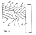
- Fig. 12 shows a detailed structure of nozzles 87.
- Nozzles 87 includes an inclined cylindrical sidewalls 87 having, an angle ⁇ with front cover 22. The angle ⁇ is depending on the direction of the water which is ejected.
- the regulated ejection of a fluid from a plurality of nozzles to form a stream that sheaths the tips of the impact tool provides absorption of vibration and noise during operation of the breaker, while preventing debris and noise from scattering.
Landscapes
- Engineering & Computer Science (AREA)
- Mechanical Engineering (AREA)
- Percussive Tools And Related Accessories (AREA)
- Earth Drilling (AREA)
- Fluid-Damping Devices (AREA)
- Pipe Accessories (AREA)
Applications Claiming Priority (2)
| Application Number | Priority Date | Filing Date | Title |
|---|---|---|---|
| KR2019980024159U KR200207572Y1 (ko) | 1998-12-04 | 1998-12-04 | 유압식 착암기의 방음 방진 장치 |
| KR9824159 | 1998-12-04 |
Publications (2)
| Publication Number | Publication Date |
|---|---|
| EP1005960A2 true EP1005960A2 (de) | 2000-06-07 |
| EP1005960A3 EP1005960A3 (de) | 2003-01-22 |
Family
ID=19540801
Family Applications (1)
| Application Number | Title | Priority Date | Filing Date |
|---|---|---|---|
| EP99118866A Withdrawn EP1005960A3 (de) | 1998-12-04 | 1999-09-24 | Ein Schall- und Staub geschützter Bohrhammer |
Country Status (3)
| Country | Link |
|---|---|
| US (1) | US6227307B1 (de) |
| EP (1) | EP1005960A3 (de) |
| KR (1) | KR200207572Y1 (de) |
Cited By (1)
| Publication number | Priority date | Publication date | Assignee | Title |
|---|---|---|---|---|
| WO2012082461A1 (en) * | 2010-12-14 | 2012-06-21 | Caterpillar Inc. | Lower damper for demolition hammer |
Families Citing this family (25)
| Publication number | Priority date | Publication date | Assignee | Title |
|---|---|---|---|---|
| USD457534S1 (en) | 2000-11-03 | 2002-05-21 | Soosan Heavy Industries Co., Ltd. | Hydraulic breaker |
| FI121223B (fi) * | 2004-07-01 | 2010-08-31 | Sandvik Mining & Constr Oy | Rikotusvasara, rikotusvasaran kiinnityskappale, rikotusvasaran sivulevy sekä rikotusvasaran suojakotelo |
| JP4559156B2 (ja) * | 2004-08-18 | 2010-10-06 | 株式会社東洋空機製作所 | ブレーカ取付用ブラケット |
| KR100630438B1 (ko) * | 2005-04-29 | 2006-10-04 | 김형구 | 저소음형 유압브레이커 |
| DE102005000179A1 (de) * | 2005-12-07 | 2007-06-14 | Hilti Ag | Hammerschlaggerät |
| US20070246237A1 (en) * | 2006-04-24 | 2007-10-25 | Emile Homsi | Vibration dampening of a power tool |
| US8061439B2 (en) * | 2007-10-16 | 2011-11-22 | Craig Nelson | Isolator plate assembly for rock breaking device |
| US9089995B2 (en) | 2007-10-16 | 2015-07-28 | Craig Nelson | Isolator plate assembly for rock breaking device |
| US7681658B2 (en) * | 2007-11-06 | 2010-03-23 | Maurice DUVAL | Pneumatic impact tool |
| WO2010137826A2 (ko) * | 2009-05-25 | 2010-12-02 | Lee Young Seok | 유압 브레이커 |
| US8121736B1 (en) * | 2009-08-07 | 2012-02-21 | The Boeing Company | Air spindle with closed loop speed control |
| USD645480S1 (en) * | 2009-11-23 | 2011-09-20 | Caterpillar Inc. | Hammer |
| USD645481S1 (en) * | 2009-11-23 | 2011-09-20 | Caterpillar Inc. | Hammer |
| DE102011007433A1 (de) * | 2010-04-20 | 2011-12-08 | Robert Bosch Gmbh | Handwerkzeugmaschinenvorrichtung |
| US8360167B2 (en) | 2010-08-11 | 2013-01-29 | Caterpillar Inc. | Composite seal for a hydraulic hammer |
| US8978781B2 (en) * | 2010-12-07 | 2015-03-17 | Robert Bosch Gmbh | Dust shroud for power tools |
| US8672052B2 (en) | 2010-12-14 | 2014-03-18 | Caterpillar Inc. | Demolition hammer with reversible housing and interchangeable wear plate arrangement |
| USD709529S1 (en) * | 2013-05-17 | 2014-07-22 | Company Wrench, Ltd. | Hydraulic breaker vehicle bracket |
| USD709530S1 (en) * | 2013-05-17 | 2014-07-22 | Company Wrench, Ltd. | Hydraulic breaker vehicle tool and bracket assembly |
| USD709526S1 (en) * | 2013-05-17 | 2014-07-22 | Company Wrench, Ltd. | Hydraulic breaker vehicle |
| EP3096049A4 (de) * | 2014-01-14 | 2017-07-05 | NSK Ltd. | Drehmechanismus, werkzeugmaschine und vorrichtung zur halbleiterherstellung |
| USD715330S1 (en) * | 2014-02-12 | 2014-10-14 | Company Wrench, Ltd. | Auxiliary power unit excavator |
| USD715331S1 (en) * | 2014-02-12 | 2014-10-14 | Company Wrench, Ltd. | Auxiliary power unit excavator |
| USD871461S1 (en) * | 2017-06-16 | 2019-12-31 | Il Jae Lee | Hydraulic breaker |
| US11752612B2 (en) * | 2020-11-23 | 2023-09-12 | Caterpillar Inc. | Dust suppression system for hammers |
Family Cites Families (30)
| Publication number | Priority date | Publication date | Assignee | Title |
|---|---|---|---|---|
| US819756A (en) * | 1904-08-12 | 1906-05-08 | Henry Hellman | Rock-drilling machine. |
| US2059048A (en) * | 1934-05-02 | 1936-10-27 | Ingersoll Rand Co | Rock drill |
| US2033527A (en) * | 1934-08-27 | 1936-03-10 | Roy E Kitching | Pneumatic well drill |
| US2558165A (en) | 1947-10-17 | 1951-06-26 | Ingersoll Rand Co | Cushioning device for rock drills |
| US2672129A (en) * | 1949-03-17 | 1954-03-16 | Chicago Pneumatic Tool Co | Chipping hammer |
| US2748750A (en) * | 1953-01-13 | 1956-06-05 | Armour Res Found | Vibrationless pneumatic impact tool |
| US3223181A (en) | 1962-03-27 | 1965-12-14 | Vernon L Price | Vibrationless air hammer assembly |
| US3198265A (en) * | 1962-12-26 | 1965-08-03 | Frank J Voelkerding | Gas leak detection device |
| US3168324A (en) | 1963-02-15 | 1965-02-02 | Ingersoll Rand Co | Chuck |
| US3332504A (en) * | 1964-05-18 | 1967-07-25 | James V Lowery | Impact tool |
| FR1452240A (fr) * | 1965-07-23 | 1966-02-25 | Montabert Ets | Perfectionnement aux outils pour marteaux pneumatiques |
| DE1558974A1 (de) * | 1967-09-26 | 1970-04-02 | Grossbohrloch Und Spreng Unter | Ringtieflochhammer |
| US3456744A (en) * | 1967-11-24 | 1969-07-22 | Samuel Altschuler | Vibrationless pneumatic tool |
| US3496840A (en) * | 1968-01-29 | 1970-02-24 | Fastener Corp | Fastener driving apparatus |
| US3559753A (en) | 1969-05-21 | 1971-02-02 | Ilmar Meri | Percussion tool |
| US3662855A (en) | 1970-05-04 | 1972-05-16 | Robert D Adams | Muffled tool for vibratory or impact machines |
| GB1345341A (en) | 1971-03-03 | 1974-01-30 | Devac Ab | Percussion machine |
| US3757875A (en) * | 1971-11-24 | 1973-09-11 | Kent Air Tool Co | Air hammer and combined support and muffler therefor |
| US4018291A (en) * | 1974-12-23 | 1977-04-19 | Allied Steel & Tractor Products, Incorporated | Pneumatic hammer |
| US4327807A (en) * | 1978-09-19 | 1982-05-04 | Maco-Meudon | Percussion tool casing |
| JPS5920815B2 (ja) | 1980-05-23 | 1984-05-15 | 十三男 鈴木 | 油水圧圧入圧出装置 |
| US4402383A (en) * | 1981-09-01 | 1983-09-06 | Joy Manufacturing Company | Drill motor enclosure |
| US4440237A (en) | 1982-06-11 | 1984-04-03 | Ingersoll-Rand Co. | Pavement breaker |
| FR2554752B1 (fr) * | 1983-11-10 | 1986-12-26 | Charbonnages De France | Carter insonorisant pour marteau pneumatique de foration |
| ATE74550T1 (de) | 1985-11-04 | 1992-04-15 | Quarry Eng Dev Pty Ltd | Felsenbrechanlage. |
| US4854393A (en) * | 1987-12-03 | 1989-08-08 | Palet Timothy J | Combination air hammer, water stream blaster and liquid mist dust suppressor |
| DK543289D0 (da) * | 1989-10-31 | 1989-10-31 | Wejra A S | Trykmiddeldrevet slagvaerktoej, isaer hydraulisk hammer |
| US5419404A (en) * | 1990-05-23 | 1995-05-30 | Bretec Oy | Hydraulic impact hammer |
| US5325929A (en) * | 1991-07-09 | 1994-07-05 | Bretec Oy | Hydraulic impact hammer |
| JP3177535B2 (ja) * | 1992-03-16 | 2001-06-18 | 日本ニューマチック工業株式会社 | 衝撃動工具の支持装置 |
-
1998
- 1998-12-04 KR KR2019980024159U patent/KR200207572Y1/ko not_active Expired - Lifetime
-
1999
- 1999-08-23 US US09/378,964 patent/US6227307B1/en not_active Expired - Fee Related
- 1999-09-24 EP EP99118866A patent/EP1005960A3/de not_active Withdrawn
Cited By (2)
| Publication number | Priority date | Publication date | Assignee | Title |
|---|---|---|---|---|
| WO2012082461A1 (en) * | 2010-12-14 | 2012-06-21 | Caterpillar Inc. | Lower damper for demolition hammer |
| US8708061B2 (en) | 2010-12-14 | 2014-04-29 | Caterpillar Inc. | Lower damper for demolition hammer |
Also Published As
| Publication number | Publication date |
|---|---|
| US6227307B1 (en) | 2001-05-08 |
| KR200207572Y1 (ko) | 2001-01-15 |
| KR20000011575U (ko) | 2000-07-05 |
| EP1005960A3 (de) | 2003-01-22 |
Similar Documents
| Publication | Publication Date | Title |
|---|---|---|
| US6227307B1 (en) | Sound and dust proof breaker | |
| EP0661140B1 (de) | Eintreibewerkzeug für Befestigungsmittel | |
| CN1068819C (zh) | 减震冲击工具及其隔震器 | |
| US8360168B2 (en) | Power tool | |
| US6196331B1 (en) | Air supply and exhaust system for pneumatic tool | |
| CN102458777A (zh) | 作业工具 | |
| DE60035443D1 (de) | Schlagbohrmaschine | |
| JPH03208572A (ja) | 手持式ハンマ機械 | |
| US5137096A (en) | Dust boot and protective shroud for impact hammer | |
| US4102534A (en) | Pneumatic hammer | |
| US5797463A (en) | Pneumatic hammer | |
| JP3843124B2 (ja) | 空気圧衝撃ブレーカー | |
| US6125952A (en) | Percussive down-the-hole hammer and a drill bit therefor | |
| JP3271970B2 (ja) | 手持ち式ハンマ機械 | |
| JPS61237605A (ja) | 耐火材、コンクリ−ト材等の表面削り機 | |
| US3901332A (en) | Apparatus for removing detritus from drill holes | |
| US4736805A (en) | Hydraulic breaker with high pressure water attachment | |
| JPH02108786A (ja) | ラム穿孔機 | |
| US4340120A (en) | Annular casing hammer | |
| US4002079A (en) | Breathing protector boot for impactor tools | |
| KR100431905B1 (ko) | 오일튜브를 이용한 암반 발파시 발생하는 진동의 차단공법. | |
| JP2002323597A (ja) | 汚染表面除去方法および汚染表面除去装置 | |
| JP6555752B2 (ja) | エアー工具作動システム | |
| JPH05169375A (ja) | 手持ち式打撃工具の防振ハンドル | |
| JPH0679652A (ja) | 空気圧往復動工具 |
Legal Events
| Date | Code | Title | Description |
|---|---|---|---|
| PUAI | Public reference made under article 153(3) epc to a published international application that has entered the european phase |
Free format text: ORIGINAL CODE: 0009012 |
|
| AK | Designated contracting states |
Kind code of ref document: A2 Designated state(s): AT BE CH CY DE DK ES FI FR GB GR IE IT LI LU MC NL PT SE |
|
| AX | Request for extension of the european patent |
Free format text: AL;LT;LV;MK;RO;SI |
|
| PUAL | Search report despatched |
Free format text: ORIGINAL CODE: 0009013 |
|
| AK | Designated contracting states |
Kind code of ref document: A3 Designated state(s): AT BE CH CY DE DK ES FI FR GB GR IE IT LI LU MC NL PT SE |
|
| AX | Request for extension of the european patent |
Free format text: AL;LT;LV;MK;RO;SI |
|
| 17P | Request for examination filed |
Effective date: 20030718 |
|
| AKX | Designation fees paid |
Designated state(s): BE DE FR GB |
|
| 17Q | First examination report despatched |
Effective date: 20060829 |
|
| STAA | Information on the status of an ep patent application or granted ep patent |
Free format text: STATUS: THE APPLICATION IS DEEMED TO BE WITHDRAWN |
|
| 18D | Application deemed to be withdrawn |
Effective date: 20070109 |