EP1005966A1 - Betonplatten und Betonsteine, sowie Verfahren zu deren Herstellung - Google Patents
Betonplatten und Betonsteine, sowie Verfahren zu deren Herstellung Download PDFInfo
- Publication number
- EP1005966A1 EP1005966A1 EP99124121A EP99124121A EP1005966A1 EP 1005966 A1 EP1005966 A1 EP 1005966A1 EP 99124121 A EP99124121 A EP 99124121A EP 99124121 A EP99124121 A EP 99124121A EP 1005966 A1 EP1005966 A1 EP 1005966A1
- Authority
- EP
- European Patent Office
- Prior art keywords
- concrete
- plate
- segment
- plate segment
- slab
- Prior art date
- Legal status (The legal status is an assumption and is not a legal conclusion. Google has not performed a legal analysis and makes no representation as to the accuracy of the status listed.)
- Withdrawn
Links
- 238000000034 method Methods 0.000 title claims description 26
- 239000000654 additive Substances 0.000 claims abstract description 7
- 230000000996 additive effect Effects 0.000 claims abstract description 7
- 239000004575 stone Substances 0.000 claims description 20
- 239000004568 cement Substances 0.000 claims description 6
- 239000008187 granular material Substances 0.000 claims description 3
- 238000004519 manufacturing process Methods 0.000 claims description 3
- 239000000203 mixture Substances 0.000 claims description 3
- 239000013589 supplement Substances 0.000 claims description 3
- 230000007704 transition Effects 0.000 claims description 2
- 239000000463 material Substances 0.000 abstract 1
- 238000000465 moulding Methods 0.000 description 4
- 239000000975 dye Substances 0.000 description 3
- 229910052500 inorganic mineral Inorganic materials 0.000 description 2
- 239000011707 mineral Substances 0.000 description 2
- 238000002156 mixing Methods 0.000 description 2
- 238000003825 pressing Methods 0.000 description 2
- 239000011230 binding agent Substances 0.000 description 1
- 238000001035 drying Methods 0.000 description 1
- 238000007373 indentation Methods 0.000 description 1
- 230000000284 resting effect Effects 0.000 description 1
Images

Classifications
-
- B—PERFORMING OPERATIONS; TRANSPORTING
- B44—DECORATIVE ARTS
- B44C—PRODUCING DECORATIVE EFFECTS; MOSAICS; TARSIA WORK; PAPERHANGING
- B44C3/00—Processes, not specifically provided for elsewhere, for producing ornamental structures
- B44C3/10—Producing and filling perforations, e.g. tarsia plates
-
- B—PERFORMING OPERATIONS; TRANSPORTING
- B28—WORKING CEMENT, CLAY, OR STONE
- B28B—SHAPING CLAY OR OTHER CERAMIC COMPOSITIONS; SHAPING SLAG; SHAPING MIXTURES CONTAINING CEMENTITIOUS MATERIAL, e.g. PLASTER
- B28B1/00—Producing shaped prefabricated articles from the material
- B28B1/008—Producing shaped prefabricated articles from the material made from two or more materials having different characteristics or properties
-
- B—PERFORMING OPERATIONS; TRANSPORTING
- B28—WORKING CEMENT, CLAY, OR STONE
- B28B—SHAPING CLAY OR OTHER CERAMIC COMPOSITIONS; SHAPING SLAG; SHAPING MIXTURES CONTAINING CEMENTITIOUS MATERIAL, e.g. PLASTER
- B28B3/00—Producing shaped articles from the material by using presses; Presses specially adapted therefor
- B28B3/02—Producing shaped articles from the material by using presses; Presses specially adapted therefor wherein a ram exerts pressure on the material in a moulding space; Ram heads of special form
- B28B3/08—Producing shaped articles from the material by using presses; Presses specially adapted therefor wherein a ram exerts pressure on the material in a moulding space; Ram heads of special form with two or more rams per mould
-
- B—PERFORMING OPERATIONS; TRANSPORTING
- B28—WORKING CEMENT, CLAY, OR STONE
- B28B—SHAPING CLAY OR OTHER CERAMIC COMPOSITIONS; SHAPING SLAG; SHAPING MIXTURES CONTAINING CEMENTITIOUS MATERIAL, e.g. PLASTER
- B28B3/00—Producing shaped articles from the material by using presses; Presses specially adapted therefor
- B28B3/02—Producing shaped articles from the material by using presses; Presses specially adapted therefor wherein a ram exerts pressure on the material in a moulding space; Ram heads of special form
- B28B3/08—Producing shaped articles from the material by using presses; Presses specially adapted therefor wherein a ram exerts pressure on the material in a moulding space; Ram heads of special form with two or more rams per mould
- B28B3/083—The juxtaposed rams working in the same direction
-
- B—PERFORMING OPERATIONS; TRANSPORTING
- B28—WORKING CEMENT, CLAY, OR STONE
- B28B—SHAPING CLAY OR OTHER CERAMIC COMPOSITIONS; SHAPING SLAG; SHAPING MIXTURES CONTAINING CEMENTITIOUS MATERIAL, e.g. PLASTER
- B28B7/00—Moulds; Cores; Mandrels
- B28B7/0091—Transformable moulds allowing the change of shape of an initial moulded preform by preform deformation or the change of its size by moulding on the preform
-
- B—PERFORMING OPERATIONS; TRANSPORTING
- B28—WORKING CEMENT, CLAY, OR STONE
- B28B—SHAPING CLAY OR OTHER CERAMIC COMPOSITIONS; SHAPING SLAG; SHAPING MIXTURES CONTAINING CEMENTITIOUS MATERIAL, e.g. PLASTER
- B28B7/00—Moulds; Cores; Mandrels
- B28B7/0097—Press moulds; Press-mould and press-ram assemblies
-
- B—PERFORMING OPERATIONS; TRANSPORTING
- B44—DECORATIVE ARTS
- B44C—PRODUCING DECORATIVE EFFECTS; MOSAICS; TARSIA WORK; PAPERHANGING
- B44C5/00—Processes for producing special ornamental bodies
- B44C5/04—Ornamental plaques, e.g. decorative panels, decorative veneers
- B44C5/0438—Ornamental plaques, e.g. decorative panels, decorative veneers containing stone elements
-
- E—FIXED CONSTRUCTIONS
- E04—BUILDING
- E04C—STRUCTURAL ELEMENTS; BUILDING MATERIALS
- E04C2/00—Building elements of relatively thin form for the construction of parts of buildings, e.g. sheet materials, slabs, or panels
- E04C2/02—Building elements of relatively thin form for the construction of parts of buildings, e.g. sheet materials, slabs, or panels characterised by specified materials
- E04C2/04—Building elements of relatively thin form for the construction of parts of buildings, e.g. sheet materials, slabs, or panels characterised by specified materials of concrete or other stone-like material; of asbestos cement; of cement and other mineral fibres
Definitions
- the present invention relates to concrete slabs and concrete blocks, as well as a Process for their production ..
- the object of the present invention is a concrete slab or a Concrete block, with a face that can be created in at least two differently designed zones is divided.
- this object is achieved by a method Claim 1, or a stone or a plate according to claim 14 solved.
- a form is used in the method according to the invention, which has a bottom plate, the surface of which can be partially lifted Plate segment is formed.
- This plate segment becomes relative to the remaining surface of the base plate raised so that the base plate a has a graduated surface.
- the surface of the bottom plate which is deeper than the surface of the raised plate segment is now with a Layer of a first concrete covered.
- the second concrete differs from the first concrete by at least distinguishes a supplement or an additive. So can be the first and second concrete e.g. by an added dye and / or by a differentiate the added granules.
- first Zone formed by the first concrete and the shape of the originally has a lower surface of the base plate, and one second zone formed by the second concrete and the shape of the originally raised plate segment.
- the second concrete forms in the finished stone or in the finished slab a basic body, so to speak, in the surface of which a motif insert is embedded in the first concrete, which is sharply contoured, i.e. without flowing away the Boundary, separated from the basic body. It is particularly important to emphasize that when the stone or slab hardens, the grain scaffolds in the Motif insert and the base body at their interfaces by a uniformly hardened cement stone are cemented together so that a there is an optimal bond between the base body and the motif insert.
- the method according to the invention therefore makes it possible in a simple manner Concrete blocks and concrete slabs that have a surface with a have permanent motif inlay, which is from the surface of the Basic body etc. through a different color scheme and / or Can distinguish surface structure.
- the finished stone or slab also has a flat surface on.
- the motif insert protrude from the basic body, or the To design a motif insert as a recess in the base body. For this, in End position of the plate segment after lowering, the surface of the Plate segments higher or lower than the remaining surface of the base plate lie.
- the plate segment is advantageously raised hydraulically or pneumatic, with a hydraulic when lowering the plate segment or pneumatic pressure is reduced in a controlled manner using a throttle valve.
- the lowering speed of the plate segment important for the contour sharpness can thus be controlled with simple means.
- the contour sharpness can also be improved in that the Shaking or vibrating the mold when lowering the first plate segment mainly includes vertical movements.
- the actual pressing process preferably takes place during the Lowering of the plate segment instead.
- the level difference between the surface of the plate segment and the surface of the rest Base plate should preferably be between 5 and 15 mm. Larger Differences in level than 15 mm are of course also possible. she however, require that larger amounts of the second concrete when lowering the Disk segments must be redistributed. However, they hardly bring Advantages, since a layer thickness of only 5-10 mm is sufficient Guaranteed durability for the motif insert.
- the concrete is advantageously entered into the mold as follows. To Lifting the slab segment, the first concrete is on the floor slab abandoned and then level with the surface of the raised Strip segments stripped. After stripping is then a Form frame placed around the base plate, or by an additional side part completed. Then the second concrete is poured into the mold.
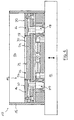
- FIG 1 is a form 10 for the inventive method on a Vibrating table 11 shown.
- the mold 10 comprises a base plate soft overall is designated by the reference numeral 12 and a molding space 14 downwards limited.
- the mold space 14 is delimited laterally by a mold frame 15.
- a part of the base plate 12 is designed as a plate segment 16 which relative to the rest of the base plate by means of pneumatic or hydraulic Printing cylinder 18, 20 can be raised in the mold space 14.
- the plate segment 16 is shown in the raised state.
- the bottom plate 12 has a stepped surface, on the one hand by a Form space 14 facing surface 20 of the raised plate segment 16 and on the other hand by a surface 22 facing the molding space 14 a motif insert 24 is formed.
- the bottom plate 12 has a recess 26, the bottom surface of which the surface 22 of the Motif insert 24 and its side surfaces by side edges 26, 28, 30th of the raised plate segment 16 are formed. Note that the side edges 26, 28, 30 of the raised plate segment 16, the Partially cover the side edges of the motif insert 24 laterally.
- the Level difference between the surface 20 of the raised Plate segment 16 and the surface 22 of the motif insert 24 is preferably between 5 and 15 mm.
- first concrete 32 on the motif insert 22.
- a mixture of a binder and at least one Surcharge usually, a damp concrete comes from cement and one mineral surcharge used.
- the concrete can also contain a dye or contain granules as an additive.
- this will be the first Concrete 32 level with surface 20 of the raised slab segment 16 stripped.
- Figure 2 shows the stripped layer of the first concrete 32 in the Indentation 25 of the base plate 12.
- the mold frame 15 is preferably only after denying the Base plate 12 lowered, or closed after denial.
- the vibrating table 11 can be actuated briefly before stripping to evenly distribute the first concrete in the recess 25 and easy to pre-compact.
- the molding space 14 is then covered with a second concrete 34 replenished.
- the first and second concrete differ in this at least one supplement or additive, so that they in the cured form visually different surfaces.
- the second layer of concrete 34 covers the surface 20 of the Slab segment 16, as well as the existing layer of the first concrete 32.
- FIG. 3 shows the mold 10 filled with the second concrete 34. Before a press ram 36 is inserted into the mold 10, one more time The vibrating table 11 can be operated briefly in order to evenly pass the second concrete 34 Distribute molding space 14.
- the raised plate segment 16 is now, preferably under constant shaking or vibrating in the vertical direction of the mold 10, slowly lowered.
- the proportion of the second follows Concrete 34 which rests on the slab segment 16 and this lowering movement lies seamlessly on the progressively released edge of the first concrete 32 on. There is no mixing of the harvested and second concrete on the Interface instead.
- the lowering of the plate segment 16 is advantageously carried out by a pneumatic throttle valve (not shown) controlled with the pneumatic pressure cylinders 18, 20 is connected. During lowering the plate segment 16, the stamp 36 exerts a pressure.
- FIG 5 shows the shape 10 after the lowering of the Plate segments 16 shown.
- the surface 20 of the plate segment 16 and the surface 22 of the motif insert 24 are in one in this end position Level.
- the punch 36 now also compresses the two concrete 34 and 32 increased pressure to achieve the necessary strength of the stone.
- the pressed stone can then be removed from the mold and Harden.
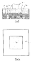
- FIG 6 is a top view of the surface of the finished stone shown, which rested on the base plate 12 of the mold 10.
- Motif insert 40 which is formed by the first concrete 32
- base body 42 formed by the second concrete 34 becomes.
- the transition at the interfaces between motif insert 40 and Base body 42 is extremely contour-sharp. If you cut the stone by, it is also found that the motif insert 40 and the base body 42 Have grain skeletons, which at their interfaces by a uniform hardened cement stone to be cemented together. The latter ensures that an optimal bond between the base body 42 and the relatively thin motif insert 40 is present.
- the method according to the invention can be extremely complex Motif deposits, almost without additional work during the Press process, permanently embed in a concrete block or a concrete slab.
- Such motif inserts can not only be simple with great contour sharpness Pattern but e.g. also company logos, letters, numbers, symbols represent.
- the motif inlays can also be designed such that a certain symbol composed by several stones or slabs becomes.
Landscapes
- Engineering & Computer Science (AREA)
- Mechanical Engineering (AREA)
- Manufacturing & Machinery (AREA)
- Chemical & Material Sciences (AREA)
- Ceramic Engineering (AREA)
- Architecture (AREA)
- Civil Engineering (AREA)
- Structural Engineering (AREA)
- Press-Shaping Or Shaping Using Conveyers (AREA)
Abstract
Description
- Fig.1:
- einen Querschnitt durch eine Form für das erfindungsgemäße Herstellen von Betonplatten und Betonsteinen mit einer konturscharfen Motiveinlage in der Oberfläche;
- Fig.2:
- die Form der Figur 1 nach Eingabe eines ersten Betons;
- Fig.3:
- die Form der Figur 2, nach Auffüllen mit einem zweiten Beton;
- Fig.4:
- die Form der Figur 3, beim Absenken eines angehobenen Plattensegments;
- Fig.5:
- die Form der Figur 4, in Endstellung;
- Fig.6:
- eine Draufsicht auf einen mit der Form gepreßten Stein.
Claims (17)
- Verfahren zum Herstellen von Betonplatten und Betonsteinen, bei dem ein Beton auf eine Bodenplatte (12) einer Form (10) aufgegeben wird und anschließend in der Form (10) in Stein- oder Plattenform gepreßt wird,
gekennzeichnet durch folgende Schritte:Einsatz einer Bodenplatte (12) deren Oberfläche (20, 22) teilweise durch ein anhebbares Plattensegment (16) ausgebildet wird;Anheben des Plattensegments (16) relativ zur restlichen Bodenplatte (24), so daß die Bodenplatte (12) eine abgestufte Oberfläche (20, 22) aufweist;Bedecken der Oberfläche (22) der Bodenplatte (12) die tiefer als die Oberfläche (20) des angehobenen Plattensegments (16) liegt mit einer Schicht eines ersten Betons (32);Auffüllen der Form (10), in der die Oberfläche des angehobenen Plattensegments (16) von dem ersten Beton (32) unbedeckt ist, mit einer Schicht eines zweiten Betons (34), wobei sich der zweite Beton (34) vom ersten Beton (32) durch mindestens einen Zuschlag oder einen Zusatzstoff unterscheidet; undAbsenken des angehobenen Plattensegments (16). - Verfahren nach Anspruch 1, dadurch gekennzeichnet, daß der erste und zweite Beton (32, 34) sich durch einen beigegeben Farbstoff unterscheiden.
- Verfahren nach Anspruch 1 oder 2, dadurch gekennzeichnet, daß der erste und zweite Beton (32, 34) sich durch ein beigegebenes Granulat unterscheiden.
- Verfahren nach einem der Ansprüche 1 bis 3, dadurch gekennzeichnet, daß in angehobener Ausgangsstellung des Plattensegmentes (16), die Kanten des Plattensegments (26, 28, 30) die Kanten der restlichen Bodenplatte (24) noch teilweise seitlich überdecken.
- Verfahren nach einem der Ansprüche 1 bis 4, dadurch gekennzeichnet, daß nach abgeschlossenem Absenken des Plattensegments (16), das Plattensegment (16) und die restliche Bodenplatte (24) eine ebene Oberfläche (20, 22) ausbilden.
- Verfahren nach einem der Ansprüche 1 bis 4, dadurch gekennzeichnet, daß nach abgeschlossenem Absenken des Plattensegments (16), das Plattensegment (16) und die restliche Bodenplatte (24) eine abgestufte Oberfläche (20, 22) ausbilden.
- Verfahren nach einem der Ansprüche 1 bis 6, dadurch gekennzeichnet, daß das Anheben des Plattensegments (16) hydraulisch oder pneumatisch erfolgt.
- Verfahren nach Anspruch 7, dadurch gekennzeichnet, daß beim Absenken des Plattensegments (16) ein hydraulischer oder pneumatischer Druck kontrolliert über ein Drosselventil abgebaut wird.
- Verfahren nach einem der Ansprüche 1 bis 8, dadurch gekennzeichnet, daß das Absenken des Plattensegments (16) unter ständigem Rütteln oder Vibrieren der Form (10) erfolgt.
- Verfahren nach Anspruch 9, dadurch gekennzeichnet, daß das Rütteln oder Vibrieren der Form (10) beim Absenken des Plattensegmentes (16) hauptsächlich vertikale Bewegungen umfaßt.
- Verfahren nach einem der Ansprüche 1 bis 10, dadurch gekennzeichnet, daß die Betonschichten (32, 34) beim Absenken des Plattensegmentes (16) zusammengepreßt werden.
- Verfahren nach einem der Ansprüche 1 bis 11, dadurch gekennzeichnet, daß nach Anheben des Plattensegments (16), der Niveauunterschied zwischen der Oberfläche (20) des Plattensegments (16) und der Oberfläche (22) der restlichen Bodenplatte (24) zwischen 5 und 15 mm beträgt.
- Verfahren nach einem der Ansprüche 1 bis 12, dadurch gekennzeichnet, daßnach Anheben des Plattensegments (16), der erste Beton (32) auf die Bodenplatte (12) aufgegeben wird und anschließend niveaugleich zur Oberfläche des angehobenen Plattensegments (16) abgestreift wird;nach erfolgtem Abstreiten ein Formrahmen (15) über die Bodenplatte abgesenkt, bzw. geschlossen wird; undanschließend der zweite Beton (34) in die Form (10) eingegeben wird.
- Stein oder Platte aus einem gepreßten Betongemisch gekennzeichnet durch einen Grundkörper (42) mit mindestens einer Motiveinlage (40) in einer Oberfläche des Grundkörpers (42), wobei Motiveinlage (40) und Grundkörper (42) aus Betons (32, 34) bestehen die sich durch mindestens einen Zuschlag oder einen Zusatzstoff unterscheiden, der Übergang in der Oberfläche zwischen Motiveinlage (40) und Grundkörper (42) konturscharf ausgebildet ist, und Motiveinlage (40) und Grundkörper (42) Korngerüste aufweisen, welche an ihren Grenzflächen durch einen einheitlich ausgehärteteten Zementstein zusammengekittet werden.
- Stein oder Platte nach Anspruch 14, dadurch gekennzeichnet, daß die Motiveinlage (40) eine Dicke zwischen 5 und 15 mm aufweist.
- Stein oder Platte nach Anspruch 14 oder 15, dadurch gekennzeichnet, daß Motiveinlage (40) und Grundkörper (42) sich durch ihre Farbe unterscheiden.
- Stein oder Platte nach einem der Ansprüche 14 bis 16, dadurch gekennzeichnet, daß Motiveinlage (40) und Grundkörper (42) sich durch ihre Oberflächenstruktur unterscheiden.
Applications Claiming Priority (2)
| Application Number | Priority Date | Filing Date | Title |
|---|---|---|---|
| LU90326 | 1998-12-02 | ||
| LU90326A LU90326B1 (de) | 1998-12-02 | 1998-12-02 | Betonplatten und Betonsteine sowie Verfahren zu deren Herstellung |
Publications (1)
| Publication Number | Publication Date |
|---|---|
| EP1005966A1 true EP1005966A1 (de) | 2000-06-07 |
Family
ID=19731787
Family Applications (1)
| Application Number | Title | Priority Date | Filing Date |
|---|---|---|---|
| EP99124121A Withdrawn EP1005966A1 (de) | 1998-12-02 | 1999-12-02 | Betonplatten und Betonsteine, sowie Verfahren zu deren Herstellung |
Country Status (2)
| Country | Link |
|---|---|
| EP (1) | EP1005966A1 (de) |
| LU (1) | LU90326B1 (de) |
Families Citing this family (1)
| Publication number | Priority date | Publication date | Assignee | Title |
|---|---|---|---|---|
| CN107186864A (zh) * | 2017-07-18 | 2017-09-22 | 盐城市科博液压机械制造有限公司 | 双层路沿石砖生产模具总成 |
Citations (8)
| Publication number | Priority date | Publication date | Assignee | Title |
|---|---|---|---|---|
| DE139820C (de) * | ||||
| FR600125A (fr) * | 1925-06-27 | 1926-01-30 | Procédé et appareil pour la fabrication des carreaux de ciment en couleurs, permettant d'obtenir des dessins très fins et variés, à l'exemple des carreaux de céramique | |
| US1684525A (en) * | 1927-06-02 | 1928-09-18 | Tomarin Marcus | Method of forming cement blocks |
| GB904038A (en) * | 1959-11-16 | 1962-08-22 | Antony Lynn Hollaway | Formation of decorative finishes on concrete |
| US4254077A (en) * | 1979-09-10 | 1981-03-03 | Fontana John D | Method for making decorative inlaid concrete blocks |
| EP0027220A1 (de) * | 1979-10-12 | 1981-04-22 | Schneider GmbH & Co. | Verfahren und Vorrichtung zur Herstellung eines Leichtbauelements |
| EP0569069A1 (de) * | 1992-05-07 | 1993-11-10 | MASS S.p.A. | Form zum Herstellen von keramischen Fliesen und Vorrichtung zum Füllen dieser Form |
| EP0749815A1 (de) * | 1995-06-21 | 1996-12-27 | Franz Carl Nüdling Basaltwerke GmbH & Co. KG | Mit einer geometrischen Oberflächengestaltung versehenen Formling, sowie Verfahren und Vorrichtung zu dessen Herstellung |
-
1998
- 1998-12-02 LU LU90326A patent/LU90326B1/de active
-
1999
- 1999-12-02 EP EP99124121A patent/EP1005966A1/de not_active Withdrawn
Patent Citations (8)
| Publication number | Priority date | Publication date | Assignee | Title |
|---|---|---|---|---|
| DE139820C (de) * | ||||
| FR600125A (fr) * | 1925-06-27 | 1926-01-30 | Procédé et appareil pour la fabrication des carreaux de ciment en couleurs, permettant d'obtenir des dessins très fins et variés, à l'exemple des carreaux de céramique | |
| US1684525A (en) * | 1927-06-02 | 1928-09-18 | Tomarin Marcus | Method of forming cement blocks |
| GB904038A (en) * | 1959-11-16 | 1962-08-22 | Antony Lynn Hollaway | Formation of decorative finishes on concrete |
| US4254077A (en) * | 1979-09-10 | 1981-03-03 | Fontana John D | Method for making decorative inlaid concrete blocks |
| EP0027220A1 (de) * | 1979-10-12 | 1981-04-22 | Schneider GmbH & Co. | Verfahren und Vorrichtung zur Herstellung eines Leichtbauelements |
| EP0569069A1 (de) * | 1992-05-07 | 1993-11-10 | MASS S.p.A. | Form zum Herstellen von keramischen Fliesen und Vorrichtung zum Füllen dieser Form |
| EP0749815A1 (de) * | 1995-06-21 | 1996-12-27 | Franz Carl Nüdling Basaltwerke GmbH & Co. KG | Mit einer geometrischen Oberflächengestaltung versehenen Formling, sowie Verfahren und Vorrichtung zu dessen Herstellung |
Also Published As
| Publication number | Publication date |
|---|---|
| LU90326B1 (de) | 2000-06-05 |
Similar Documents
| Publication | Publication Date | Title |
|---|---|---|
| DE2416764C2 (de) | Verfahren zur Herstellung eines Bauelementes und Vorrichtung zur Durchführung dieses Verfahrens | |
| DE69908273T2 (de) | Presswerkzeug aus Beton und Verfahren zur dessen Herstellung | |
| DE3733707C2 (de) | Betonstein | |
| DE69710782T2 (de) | Verfahren und Vorrichtung zum Herstellen von Betongegenständen mit sichtbaren Zuschlagstoffen | |
| DE1584564A1 (de) | Verfahren und Vorrichtung zum Pressen von mit einem Muster versehenen Fliesen aus Zement,Keramik u. dgl. | |
| DE3505465A1 (de) | Verfahren zur herstellung eines mauerwerksteines | |
| DE19808494C2 (de) | Verfahren zur Herstellung von künstlichen Pflastersteinen, sowie hiermit hergestellte Pflastersteine und Pflasterdecke hiermit | |
| DE102024103962A1 (de) | Pflasterstein, Verfahren zum Herstellen eines Pflastersteins und Produktionslage oder Palettenlage von Pflastersteinen | |
| EP0510486B1 (de) | Verbundstein bzw. Verbundplatte | |
| DE102019100590A1 (de) | Betonpflasterstein sowie Produktlage von Betonpflastersteinen sowie Verfahren zur Herstellung von Betonpflastersteinen in einer Produktlage | |
| DE3109108A1 (de) | "beton-formplatte mit abfasung" | |
| DE4244333C2 (de) | Verbundstein oder Verbundplatte | |
| EP0749815A1 (de) | Mit einer geometrischen Oberflächengestaltung versehenen Formling, sowie Verfahren und Vorrichtung zu dessen Herstellung | |
| EP1568455A2 (de) | Pflasterplatte aus Beton und Vorrichtung zur Herstellung von Pflasterplatten aus Beton | |
| DE2758259A1 (de) | Verfahren und vorrichtung zum herstellen von betonsteinen | |
| DE3702313C1 (en) | Process for producing a concrete paving stone or a concrete slab with a chippings layer | |
| DE29607260U1 (de) | Vorrichtung zum Herstellen von Betonsteinen mit Oberflächenmuster | |
| DE4443475A1 (de) | Verfahren zur Kennzeichnung von Betonkörpern und Formkasten zur Durchführung dieses Verfahrens | |
| DE19528861A1 (de) | Verfahren zum Herstellen einer Gehweg-Platte aus Beton, insbesondere einer geschliffenen Gartenplatte, die an der sichtseitigen Plattenoberfläche andersfarbige Flächenbereiche aufweist | |
| WO2001008859A1 (de) | Verfahren zum herstellen von hohlbausteinen und vorrichtung zur durchführung des verfahrens | |
| DE10041218A1 (de) | Künstliches Bruchstein-Pflaster und Verfahren zu dessen Herstellung | |
| EP0960989A1 (de) | Baustein und Verfahren zum Herstellen eines Bausteines aus Beton | |
| DE19844073B4 (de) | Verfahren zum Herstellen eines Belagelementes, insbesondere eines Pflastersteines oder einer Bodenplatte | |
| EP0675228A2 (de) | Pflasterstein, sonstiger Pflasterblock oder Pflasterplatte | |
| DE3831726C1 (en) | Process for producing a moulded brick in the shape of a truncated cone for gas bubble bricks |
Legal Events
| Date | Code | Title | Description |
|---|---|---|---|
| PUAI | Public reference made under article 153(3) epc to a published international application that has entered the european phase |
Free format text: ORIGINAL CODE: 0009012 |
|
| AK | Designated contracting states |
Kind code of ref document: A1 Designated state(s): AT BE CH CY DE DK ES FI FR GB GR IE IT LI LU MC NL PT SE |
|
| AX | Request for extension of the european patent |
Free format text: AL;LT;LV;MK;RO;SI |
|
| 17P | Request for examination filed |
Effective date: 20001014 |
|
| AKX | Designation fees paid |
Free format text: AT BE CH CY DE DK ES FI FR GB GR IE IT LI LU MC NL PT SE |
|
| 17Q | First examination report despatched |
Effective date: 20020917 |
|
| STAA | Information on the status of an ep patent application or granted ep patent |
Free format text: STATUS: THE APPLICATION IS DEEMED TO BE WITHDRAWN |
|
| 18D | Application deemed to be withdrawn |
Effective date: 20031107 |