EP1006032B1 - Module de roue pour une voiture - Google Patents
Module de roue pour une voiture Download PDFInfo
- Publication number
- EP1006032B1 EP1006032B1 EP99118947A EP99118947A EP1006032B1 EP 1006032 B1 EP1006032 B1 EP 1006032B1 EP 99118947 A EP99118947 A EP 99118947A EP 99118947 A EP99118947 A EP 99118947A EP 1006032 B1 EP1006032 B1 EP 1006032B1
- Authority
- EP
- European Patent Office
- Prior art keywords
- wheel
- signal
- module
- vehicle
- module according
- Prior art date
- Legal status (The legal status is an assumption and is not a legal conclusion. Google has not performed a legal analysis and makes no representation as to the accuracy of the status listed.)
- Expired - Lifetime
Links
- 238000004364 calculation method Methods 0.000 claims description 9
- 230000006870 function Effects 0.000 claims description 8
- 230000001133 acceleration Effects 0.000 claims description 4
- 238000000034 method Methods 0.000 description 6
- 230000005540 biological transmission Effects 0.000 description 5
- 238000011161 development Methods 0.000 description 4
- 230000018109 developmental process Effects 0.000 description 4
- 238000012545 processing Methods 0.000 description 4
- 238000011156 evaluation Methods 0.000 description 3
- 230000001419 dependent effect Effects 0.000 description 2
- 238000005315 distribution function Methods 0.000 description 2
- 238000009434 installation Methods 0.000 description 2
- 230000006978 adaptation Effects 0.000 description 1
- 230000000903 blocking effect Effects 0.000 description 1
- 238000006243 chemical reaction Methods 0.000 description 1
- 230000001934 delay Effects 0.000 description 1
- 238000013461 design Methods 0.000 description 1
- 230000000116 mitigating effect Effects 0.000 description 1
- 230000001737 promoting effect Effects 0.000 description 1
- 230000003313 weakening effect Effects 0.000 description 1
Images
Classifications
-
- B—PERFORMING OPERATIONS; TRANSPORTING
- B60—VEHICLES IN GENERAL
- B60T—VEHICLE BRAKE CONTROL SYSTEMS OR PARTS THEREOF; BRAKE CONTROL SYSTEMS OR PARTS THEREOF, IN GENERAL; ARRANGEMENT OF BRAKING ELEMENTS ON VEHICLES IN GENERAL; PORTABLE DEVICES FOR PREVENTING UNWANTED MOVEMENT OF VEHICLES; VEHICLE MODIFICATIONS TO FACILITATE COOLING OF BRAKES
- B60T13/00—Transmitting braking action from initiating means to ultimate brake actuator with power assistance or drive; Brake systems incorporating such transmitting means, e.g. air-pressure brake systems
- B60T13/10—Transmitting braking action from initiating means to ultimate brake actuator with power assistance or drive; Brake systems incorporating such transmitting means, e.g. air-pressure brake systems with fluid assistance, drive, or release
- B60T13/66—Electrical control in fluid-pressure brake systems
- B60T13/662—Electrical control in fluid-pressure brake systems characterised by specified functions of the control system components
-
- B—PERFORMING OPERATIONS; TRANSPORTING
- B60—VEHICLES IN GENERAL
- B60T—VEHICLE BRAKE CONTROL SYSTEMS OR PARTS THEREOF; BRAKE CONTROL SYSTEMS OR PARTS THEREOF, IN GENERAL; ARRANGEMENT OF BRAKING ELEMENTS ON VEHICLES IN GENERAL; PORTABLE DEVICES FOR PREVENTING UNWANTED MOVEMENT OF VEHICLES; VEHICLE MODIFICATIONS TO FACILITATE COOLING OF BRAKES
- B60T8/00—Arrangements for adjusting wheel-braking force to meet varying vehicular or ground-surface conditions, e.g. limiting or varying distribution of braking force
- B60T8/32—Arrangements for adjusting wheel-braking force to meet varying vehicular or ground-surface conditions, e.g. limiting or varying distribution of braking force responsive to a speed condition, e.g. acceleration or deceleration
- B60T8/321—Arrangements for adjusting wheel-braking force to meet varying vehicular or ground-surface conditions, e.g. limiting or varying distribution of braking force responsive to a speed condition, e.g. acceleration or deceleration deceleration
Definitions
- the invention relates to a wheel module for a vehicle having an electrically controllable brake system (EBS) for controlling the braking force on at least one wheel of the vehicle according to the preamble of patent claim 1.
- EBS electrically controllable brake system
- Such a wheel module is known from EP 0 467 112 B1.
- the known wheel module is part of an electrically controllable brake system, Radmoduln, central modules and encoder devices, such.
- B. has a brake value transmitter.
- the known wheel module is associated with a wheel of a vehicle. By means of a same wheel associated with the rotational speed sensor, a signal representing the rotational speed of the wheel is generated and fed to the wheel module associated with this wheel for evaluation.
- An electronic control device with a microprocessor arranged in the wheel module evaluates this signal and transmits a speed signal calculated therefrom via a data bus system. Via the data bus system, several wheel modules, each of which emit a speed signal, are connected to a central module.
- the central module evaluates the speed signals received from the data bus system and calculates from this z.
- B. a vehicle reference speed, which is required for anti-skid control. This vehicle reference speed and possibly further calculation results required for anti-skid control then sends the central module back to the wheel modules, which then use this data for an anti-skid control on their associated wheel.
- the invention is therefore based on the object to provide a wheel module and a brake system, in which the cost of data transmission is reduced.
- the invention has the advantage that the cost of data transmission between the modules of the brake system is reduced to an extremely low level by the necessary for a brake control with anti-lock control, calculated from the input signals computation results such.
- B a vehicle reference speed, slip signals, acceleration signals, Bremskraftverring réelles-, holding and / or reconstruction signals, not in a central location, ie in a central module, calculated and transmitted via the data bus system to the Radmoduln, but is calculated locally directly in a wheel module.
- an anti-skid control is very time-critical, also an improvement in the control quality is achieved because time delays that arise as a result of data transmission between the central module and the wheel module can be avoided.
- wheel module according to the invention can be operated without any central module or even after failure of the central module without any restrictions regarding the anti-lock control method. So even without a central module z. B. a so-called modified individual control, as known for example from DE 28 51 107 C2, are performed on a steerable axle for mitigating yaw moment changes. Other control principles, such as Variable Axis Control or Modified Axis Control, which are familiar to the person skilled in the art, can also be implemented both with and without a central module.
- Another advantage of the invention is that in each wheel module, the same control program can be provided so that regardless of the number of wheel modules used in a vehicle only a single control program is to create, so that the development effort is relatively low.
- a determination of the wheel allocation of a wheel module by input of a wheel position parameter, which is provided in an electronic control device provided in the wheel module is entered.
- This has the advantage that initially identical Radmoduln can be produced, which only at a relatively late time, z.
- a wheel assignment is necessary, for example, to a steerable axle of a vehicle, the anti-skid control according to another principle, eg. B. as already mentioned Modified individual control to perform as on a non-steerable axle of the vehicle, at the example, a so-called individual control is performed.
- the input of the Radpositionsparameters z. B. manually by operation of a diagnostic device, which transmits the Radmoduln corresponding data are made. If a central module is provided in the brake system, then according to an advantageous development of the invention, the central module automatically assigns the wheel allocation, z. B. once upon first installation of the brake system. For this purpose, information about the wheel allocation and the brake system are then stored in the central module.
- the electronic control device of a wheel module can detect on the basis of the wheel position parameter whether the speed signal should be transmitted via the data bus system or not.
- the braking system can be modularly extended by an in principle unlimited number of Radmoduln depending on the requirements of the vehicle, without the cost of data transmission increases significantly or special adaptation work would be required.
- An advantageous embodiment of the invention is to provide a brake system with several Radmoduln of the type described above and with a central module, said modules are connected to one another via one or more data bus systems for exchanging information.
- the central module preferably serves for the execution of central, only once in the vehicle required brake control functions.
- the central module is preferably assigned so-called brake management functions.
- brake management functions By this is meant for example an axle load-dependent braking force distribution function, a uniform wear of the brake pads promoting braking force distribution function or a regulation of the vehicle deceleration.
- the central module can also have other central functions, such. As a motor control as part of a traction control run.
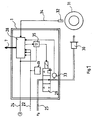
- Fig. 1 the internal structure of a wheel module (1) is shown schematically. From an electronic control device arranged in the wheel module (1), only a microcomputer (28), a nonvolatile memory module (23) and an output amplifier (35) are shown for a better overview. Further, in practice usually used and known in the art additional circuit parts, such as level adjustments, analog / digital converter, driver, etc. are not shown in detail.
- the microcomputer (28) which is preferably of the type 68010 from Motorola or another 16-bit microcomputer, is supplied with operating voltage via an electrical line (24).
- the microcomputer (28) is connected via a data bus system (7) with further Radmoduln and possibly also a central module.
- a data bus system (7) may preferably be used a CAN data bus.
- the microcomputer (28) sends an actuating signal to a valve device (29) via an output amplifier (35).
- the valve device (29) is designed as a 3/3-way valve.
- the valve device (29) depending on the control signal supplied via a pressure medium line (25) supply pressure (P B ) on the output side connected to the wheel module brake cylinder (30), which for mechanical actuation of a wheel (31) connected Wheel brake serves to be forwarded.
- the valve device (29) and the brake cylinder (30) thus form an actuator for adjusting the braking force on the wheel (31).
- the brake pressure in the brake cylinder (30) can be reduced or kept at an existing value by means of the valve device (29). In the latter two cases the brake cylinder (30) is not connected to the supply pressure (P B ).
- the brake pressure present in each case in the brake cylinder (30), which represents the actual braking force, is converted by means of a pressure sensor (33) into an electrical signal, which is supplied to the microcomputer (28).
- the microcomputer (28) is supplied with a signal generated by means of a rotational speed sensor (32) via an electrical line (34) for evaluation.
- the rotational speed sensor (32) is preferably designed as an electromagnetically acting pulse speed sensor and cooperates with a, not shown in FIG. 1, provided with a plurality of teeth pole wheel.
- the signal generated as a result of rotations of the pole wheel is a series of voltage pulses, the time interval of which is a measure of the rotational speed of the wheel (31).
- the microcomputer (28) calculates from the time intervals using additional information stored in the wheel module, e.g. the circumference of the wheel (31), a speed signal.
- the microcomputer (28) signals of other sensors, eg. B. from a brake pad wear sensor supplied. Via the line (22), the microcomputer (28) also data from a non-volatile memory device (23), z. As an EEPROM read or write data there. In the memory module (23) information such as the wheel position parameter and the circumference of the wheel (31) can be stored.
- the microcomputer (28) receives from the data bus system (7) a braking value indicative of the target braking force to be set on the wheel (31).
- the braking value is transmitted either directly from a brake value sensor connected to the brake pedal or from a central module connected to the brake value transmitter.
- the wheel module has the task to convert this braking value into a corresponding braking force or a brake pressure in the brake cylinder (30), so that the vehicle is braked in accordance with the brake pedal operation.
- the wheel module (1) can also be structurally integrated in the brake cylinder (30), resulting in a very compact design and simplified assembly.
- a brake cylinder and a plurality of brake cylinders which are assigned to the wheels of a wheel or axle group of the vehicle and are to be acted upon with the same brake pressure, are connected to the wheel module.
- a connection possibility for one or more further rotational speed sensors would be provided in the wheel module, which serve to determine the rotational speeds of the other wheels of the wheel or axle group.
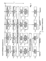
- FIG. 2 shows by way of example a sequence of individual program steps of an antilock control method as executed in the microcomputer (28).
- the antilock control method basically consists on the one hand of similar program steps (101, 102, 103, 104, 105, 201, 202, 203, 204, 205, 301, 302, 303, 304, 305, 401, to be assigned to the respective wheels), 402, 403, 404, 405) and on the other hand from common, valid for several or all wheels program steps (10, 11).
- the similar program steps to be assigned to the wheels are also referred to as control channels.
- control channel 1 consists of the program steps (101, 102, 103, 104, 105)
- control channel 2 consists of the program steps (201, 202, 203, 204, 205)
- control channel 3 consists of the program steps (301, 302, 303, 304, 305)
- control channel 4 consists of the program steps (401, 402, 403, 404, 405).
- a different number can also be used be provided by control channels, for example, two or three control channels.
- Each of the control channels is basically provided for processing an input signal from a rotational speed sensor and for outputting a control signal for a valve device.
- the illustrated anti-lock control method could thus be used in a corresponding control unit for anti-lock control of four wheels of a vehicle in the sense of a four-channel anti-lock braking system.
- the electronic control device provided in the wheel module (1) has connection possibilities only for one rotational speed sensor (32) and one valve device (29). For this reason, the signal from the rotational speed sensor (32) is supplied to only one of the control channels, which is referred to below as the main control channel, for evaluation.
- the remaining control channels hereinafter referred to as additional control channels, receive their speed information from the data bus system (7).
- a logical switch (106, 206, 306, 406) is provided, which can be adjusted by programming the wheel module in the context of wheel allocation.
- a logical selection switch (12) is provided for passing on the control signals respectively calculated by the four control channels, which switches to the same Mode is programmable and is preferably programmed so that the control signal from the main control channel to the valve means (29) is output.
- control channel 1 was defined by wheel allocation of the wheel module as the main control channel.
- the program steps (101, 201, 301, 401) are for a conversion of the rotational speed sensor (32). emitted signal, for example, the sequence of pulses with variable time interval, provided in the processing of the subsequent program steps speed signal.
- the signal from the rotational speed sensor (32) in the program step (101) is processed.
- the control channels 2, 3 and 4 receive, as mentioned, their speed information from the data bus system (7).
- the speed signal calculated in the program step (101) is also transmitted on the data bus system (7) in addition to the use in the control channel 1 (not shown).
- a separate wheel-related reference speed is calculated for each control channel (program steps 102, 202, 302, 402).
- a common vehicle reference speed is calculated from all previously calculated wheel reference speeds as the first intermediate result of the calculations.
- step (11) another intermediate result is calculated for the control channels 1 and 2, which causes in the final calculation of the control signal for the valve device, a weakening of the yawing moment on the front axle in the sense of the aforementioned modified individual control.
- variable axis control would be between the program steps (304, 404) and (305, 405) for the control channels 3 and 4 common program step analogous to the program step (11) provided in the then computing steps for the aforementioned variable axis control would be carried out.
- the main control channel which finally generates the control signal for the valve device (29), due to the direct connection to the signal from the wheel module associated rotational speed sensor (32) with a particularly frequently updated and thus very current Speed information supplied.
- the additional control channels usually receive their speed information from the data bus system (7) with a lower frequency of updates. As a result, a high control quality in dynamic operations on the wheel, in particular in the anti-skid control, can be achieved.
- the wheel position parameter contains information about the setting of the logical switches (106, 206, 306, 406, 12).
- the number of the main control channel can also be used, i. E. in the present case, the wheel position parameter would then have to be set to the value 1.
- the setting of the logic switches (106, 206, 306, 406, 12) would then be derived from this value by the microcomputer (28).
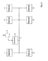
- Fig. 3 shows an arrangement of Radmoduln (1, 2, 3, 4, 5, 6) and a central module (8) is shown, for controlling the brake system of a three-axle vehicle, z. B. with a front axle and two rear axles, is used.
- the wheel modules (1, 2, 3, 4, 5, 6) are connected to one another and to the central module (8) via the data bus system (7).
- the wheel modules are all of the same type, ie they have the structure described in accordance with FIG. 1 and the program structure described according to FIG. 2.
- the central module (8) is with a Brake sensor (9) connected, which emits a signal representing the brake operation by the driver. This signal is processed in the central module (8).
- the processing result is sent via the data bus system (7) to the Radmoduln (1, 2, 3, 4, 5, 6) as a braking value.
- the central module performs, among other central, vehicle-wide brake control functions such.
- signals of further sensors or information from the wheel modules are available to the central module (8) (not shown).
- the central module (8) preferably transmits upon initial startup of the brake system or the vehicle information about the wheel allocation of a wheel module to each of Radmoduln. This information is stored in a wheel module then in the non-volatile memory (23) and is henceforth constantly available.
- the central module (8) and the brake value transmitter (9) can also be combined in one unit.
- the brake value transmitter (9) would be connected directly to the data bus system (7) via a suitable interface device.
- the transmitted by the brake value brake value then represents the braking request of the driver.
- the determination The Radzuowski the Radmoduln is in this case by using a diagnostic device, which is preferably also connected to the data bus system (7) when first putting the brake system. The diagnostic device is removed after completion of the assignment procedure.
- the wheel modules (1, 2) are associated with a steerable front axle of a vehicle.
- the Radmoduln (3, 4) are a rear axle, z. B. the drive axle, the vehicle assigned.
- the wheel position parameters in the Radmoduln (1, 2, 3, 4) are set such that the control signal that control channel of the valve device (29) is supplied, the control channel number of the numbering of the corresponding wheel module according to FIG. 3 corresponds.
- the control channel 1 is defined as a main control channel
- in the wheel module (2) is the control channel 2 main control channel and so on.
- the wheel modules (5, 6) are assigned to a further rear axle of the vehicle.
- the wheel allocation of these Radmoduln (5, 6) has been made in accordance with the Radmoduln (3, 4), which are also associated with a rear axle. Consequently, the control channel (3) has been defined as the main control channel in the wheel module (5), while the control channel (4) has been defined in the wheel module (6). If additional wheel modules are used, these would receive a corresponding wheel allocation depending on the type of vehicle axle to which they are assigned.
Landscapes
- Engineering & Computer Science (AREA)
- Transportation (AREA)
- Mechanical Engineering (AREA)
- Regulating Braking Force (AREA)
Claims (12)
- Module de roue (1) pour un véhicule comportant un système de freinage à commande électrique (EBS) pour commander la force de freinage sur au moins une roue (31) du véhicule,a) auquel est acheminée une valeur de freinage indiquant la force de freinage de consigne désirée pour la roue (31),b) auquel est acheminé un signal spécifique à la roue (31), et au moins un autre signal spécifique à une autre roue,c) qui émet à un actionneur (29, 30) un signal de positionnement calculé en utilisant la valeur de freinage et les signaux spécifiques aux roues, actionneur qui est prévu pour régler la force de freinage au niveau de la roue (31),caractérisé par un canal de régulation principal associé à la roue (31) et par au moins un canal de régulation supplémentaire dans lequel sont exécutées des étapes de calcul respectives spécifiques aux roues, le signal de positionnement étant calculé dans le canal de régulation principal en utilisant des résultats de calcul du canal de régulation supplémentaire.
- Module de roue selon la revendication 1, caractérisé en ce que le signal spécifique à la roue (31) est acheminé au module de roue avec une cadence de répétition supérieure à celle de l'autre signal spécifique à l'autre roue.
- Module de roue selon l'une des revendications précédentes, caractérisé en ce qu'à titre de signal spécifique à la roue est utilisé un signal indiquant la vitesse de rotation de la roue.
- Module de roue selon l'une des revendications précédentes, caractérisé par les éléments suivants :a) les étapes de calcul spécifiques aux roues présentent des étapes de calcul pour la régulation antiblocage d'une roue, dans lesquelles sont formés des résultats intermédiaires,b) le signal de positionnement est calculé en utilisant les résultats intermédiaires.
- Module de roue selon la revendication 4, caractérisé en ce qu'à titre de résultats intermédiaires sont déterminés des signaux de patinage, des signaux d'accélération, et/ou des signaux de réduction, de maintien et/ou de rétablissement de la force de freinage.
- Module de roue selon l'une des revendications précédentes, caractérisé en ce qu'une définition de l'association de roue est effectuée par entrée d'un paramètre de position de roue dans un dispositif de commande électronique (23, 28, 35) prévu dans le module de roue (1).
- Module de roue selon l'une des revendications précédentes, caractérisé par un capteur de vitesse de rotation (32) connecté au module de roue (1) et destiné à déterminer la vitesse de rotation de la roue (31).
- Module de roule selon la revendication 7, caractérisé en ce que lors de l'association du module de roue (1) à un essieu directeur et/ou moteur d'un véhicule, le signal reçu du capteur de vitesse de rotation (32) ou un signal dérivé de celui-ci est émis via un canal de données (7), en particulier via un système à bus de données.
- Module de roue selon la revendication 7 ou 8, caractérisé en ce que lors de l'association du module de roue (1) à un troisième ou à un autre essieu de véhicule, le signal reçu du capteur de vitesse de rotation (32) ou le signal dérivé de celui-ci n'est pas émis via le canal de données (7).
- Module de roue selon l'une des revendications précédentes, caractérisé en ce qu'un signal représentant la force de freinage réelle au niveau de la roue (31) provenant d'un autre capteur (33), en particulier un capteur de pression, est évalué.
- Système de freinage comportant plusieurs modules de roue (1, 2, 3, 4, 5, 6) selon l'une des revendications précédentes, et comportant un module central (8) pour l'exécution centralisée de fonctions de commande des freins portant sur tout le véhicule, le module central (8) étant connecté aux modules de roue (1, 2, 3, 4, 5, 6) via un ou plusieurs systèmes à bus de données (7) pour échanger des informations.
- Système de freinage selon la revendication 11, caractérisé en ce que le module central (8) transmet une information quant à l'association de roue d'un module de roue (1, 2, 3, 4, 5, 6) à ce dernier.
Applications Claiming Priority (2)
| Application Number | Priority Date | Filing Date | Title |
|---|---|---|---|
| DE19854788 | 1998-11-27 | ||
| DE19854788A DE19854788B4 (de) | 1998-11-27 | 1998-11-27 | Radmodul für ein Fahrzeug |
Publications (3)
| Publication Number | Publication Date |
|---|---|
| EP1006032A2 EP1006032A2 (fr) | 2000-06-07 |
| EP1006032A3 EP1006032A3 (fr) | 2001-05-16 |
| EP1006032B1 true EP1006032B1 (fr) | 2007-05-30 |
Family
ID=7889239
Family Applications (1)
| Application Number | Title | Priority Date | Filing Date |
|---|---|---|---|
| EP99118947A Expired - Lifetime EP1006032B1 (fr) | 1998-11-27 | 1999-09-25 | Module de roue pour une voiture |
Country Status (4)
| Country | Link |
|---|---|
| US (1) | US6216080B1 (fr) |
| EP (1) | EP1006032B1 (fr) |
| JP (1) | JP2000198431A (fr) |
| DE (2) | DE19854788B4 (fr) |
Families Citing this family (12)
| Publication number | Priority date | Publication date | Assignee | Title |
|---|---|---|---|---|
| DE10135600A1 (de) | 2001-07-20 | 2003-02-06 | Wabco Gmbh & Co Ohg | Antiblockiersystem |
| DE10161498A1 (de) * | 2001-12-14 | 2003-06-26 | Wabco Gmbh & Co Ohg | Magnetspuleneinheit |
| DE10203207B4 (de) * | 2002-01-21 | 2015-03-26 | Volkswagen Ag | Elektromechanische Bremsanlage |
| DE10221079B4 (de) | 2002-05-11 | 2011-01-20 | Wabco Gmbh | Antiblockiersystem für ein Radfahrzeug |
| US20050071070A1 (en) * | 2003-09-26 | 2005-03-31 | Peter Nilsson | Brake system with distributed electronic control units responsive to sensor input |
| DE102004059546A1 (de) * | 2004-12-09 | 2006-06-22 | Lucas Automotive Gmbh | Elektronisches System zum Betreiben einer elektromechanischen Feststell-Bremsanlage |
| FR2880322B1 (fr) * | 2005-01-06 | 2007-08-17 | Haldex Brake Products Ltd | Reseau de commande electronique central pour des systemes de commande ou de regulation de la suspension et de la dynamique des vehicules sur les vehicules lourds |
| DE102007015995B4 (de) * | 2007-04-03 | 2015-10-08 | Zf Friedrichshafen Ag | Achsmodul für ein Fahrzeug |
| DE102007021646A1 (de) | 2007-05-09 | 2008-11-13 | Wabco Gmbh | Modulator |
| DE102007059688A1 (de) * | 2007-12-12 | 2009-06-25 | Lucas Automotive Gmbh | Aktuatoreinrichtung und Verfahren zum Ansteuern der Aktuatoreinrichtung |
| DE102008009522B4 (de) | 2008-02-16 | 2021-12-16 | Zf Cv Systems Hannover Gmbh | Verfahren zur Kalibrierung von Radgeschwindigkeiten |
| DE102023203549A1 (de) * | 2023-04-19 | 2024-10-24 | Continental Automotive Technologies GmbH | Elektromechanisch betreibbare Radbremse mit zentraler Ansteuerelektronik |
Family Cites Families (11)
| Publication number | Priority date | Publication date | Assignee | Title |
|---|---|---|---|---|
| DE2851107C2 (de) | 1978-11-25 | 1990-03-08 | Wabco Westinghouse Fahrzeugbremsen GmbH, 3000 Hannover | Schaltungsanordnung zur Verbesserung der Fahrstabilität von mit blockiergeschützten Bremsanlagen ausgerüsteten Fahrzeugen |
| DE4022671A1 (de) * | 1990-07-17 | 1992-01-23 | Wabco Westinghouse Fahrzeug | Elektronisches bremssystem fuer stassenfahrzeuge |
| DE4122484A1 (de) * | 1991-07-06 | 1993-01-07 | Teves Gmbh Alfred | Schaltungsanordnung zur erkennung von radsensordefekten |
| DE4135691C2 (de) * | 1991-10-25 | 1998-04-16 | Aeg Westinghouse Transport | Anordnung zur Fahr- und Bremsregelung von Fahrzeugen, die mit mehreren Einzelrad-Antriebs- und Bremsmodulen ausgerüstet sind |
| US5288139A (en) * | 1992-06-05 | 1994-02-22 | Allied-Signal Inc. | Electropneumatic braking system |
| DE19521175C1 (de) * | 1995-06-10 | 1996-07-11 | Continental Ag | Elektrisch regelbares Bremssystem |
| JPH09207745A (ja) * | 1996-01-30 | 1997-08-12 | Nissan Motor Co Ltd | アンチスキッド制御装置 |
| DE19615203A1 (de) * | 1996-04-18 | 1997-10-23 | Bosch Gmbh Robert | Einrichtung zur Erkennung von elektromagnetischen Einstreuungen |
| DE19627731A1 (de) * | 1996-07-10 | 1998-01-15 | Abb Patent Gmbh | System für die Antriebs- und Bremsensteuerung eines Schienenfahrzeuges |
| DE19634567B4 (de) * | 1996-08-27 | 2007-11-29 | Robert Bosch Gmbh | Elektrisches Bremssystem |
| DE19713252A1 (de) * | 1997-03-29 | 1998-10-01 | Bosch Gmbh Robert | Verfahren und Vorrichtung zur Ermittlung einer die Fahrzeuggeschwindigkeit beschreibenden Größe |
-
1998
- 1998-11-27 DE DE19854788A patent/DE19854788B4/de not_active Expired - Lifetime
-
1999
- 1999-09-25 DE DE59914357T patent/DE59914357D1/de not_active Expired - Lifetime
- 1999-09-25 EP EP99118947A patent/EP1006032B1/fr not_active Expired - Lifetime
- 1999-11-24 JP JP11374544A patent/JP2000198431A/ja active Pending
- 1999-11-29 US US09/450,863 patent/US6216080B1/en not_active Expired - Lifetime
Also Published As
| Publication number | Publication date |
|---|---|
| DE19854788A1 (de) | 2000-05-31 |
| JP2000198431A (ja) | 2000-07-18 |
| DE19854788B4 (de) | 2009-12-03 |
| EP1006032A3 (fr) | 2001-05-16 |
| DE59914357D1 (de) | 2007-07-12 |
| US6216080B1 (en) | 2001-04-10 |
| EP1006032A2 (fr) | 2000-06-07 |
Similar Documents
| Publication | Publication Date | Title |
|---|---|---|
| EP0481043B1 (fr) | Systeme de regulateurs connectes entre eux-memes pour vehicules a moteur | |
| EP0467112B2 (fr) | Système de freinage électronique pour véhicules | |
| DE4227083C2 (de) | Elektronisches Bremssystem, insbesondere für Straßenfahrzeuge | |
| EP1006032B1 (fr) | Module de roue pour une voiture | |
| DE19838336A1 (de) | System zur Steuerung der Bewegung eines Fahrzeugs | |
| EP0949130B2 (fr) | Dispositif de commande d'un système de freinage de véhicule | |
| EP3642086B1 (fr) | Procédé destiné à déterminer les valeurs de décélération totale atteignables par actionnement de freins de roue d'un véhicule utilitaire, système de freinage destiné à la mise en oeuvre du procédé et véhicule utilitaire comprenant ce dernier | |
| DE112021001103T5 (de) | Fahrzeugsteuerungsvorrichtung, Fahrzeugsteuerungsverfahren und Fahrzeugsteuerungssystem | |
| EP0189077B1 (fr) | Dispositif pour la commande de la pression de freinage | |
| DE19733379A1 (de) | Verfahren und Vorrichtung zur Steuerung einer Bremsanlage | |
| WO2001026943A1 (fr) | Dispositif et procede pour reguler au moins une grandeur de deplacement d'un vehicule | |
| EP0985586B1 (fr) | Système d'antiblocage pour un système de freinage électromécanique de véhicule basé sur un régulateur de logique floue | |
| WO2000025036A1 (fr) | Procede et dispositif pour la surveillance du mouvement d'un actionneur | |
| DE19707210A1 (de) | Verfahren zur achslastabhängigen Bremskraftverteilung in einer Bremsanlage eines Fahrzeuges | |
| DE69722124T2 (de) | Verfahren zur Feststellung eines Auswechselzeitpunktes und Fahrzeugregelvorrichtung, die in der Lage ist, einen Auswechselzeitpunkt eines Betätigungsorgans anzuzeigen | |
| EP1254792B1 (fr) | Dispositif et procédé de commande de fonctions d'un véhicule | |
| DE10011269A1 (de) | Verfahren und Vorrichtung zur Steuerung einer Bremsanlage | |
| EP0914998B1 (fr) | Méthode de mise en accord des forces de freinage de deux parties reliées formant un véhicule | |
| DE102019108620B4 (de) | Verfahren und Steuereinheit zum Steuern einer Lenkbremsfunktion für ein Fahrzeug und Bremssystem für ein Fahrzeug | |
| EP3500460B1 (fr) | Procédé de réglage des pressions de freinage, système de freinage d'un véhicule à moteur pour la mise en oeuvre de ce procédé et véhicule à moteur doté d'un tel système de freinage | |
| EP4077075B1 (fr) | Architecture d'un système de freinage électronique | |
| EP2213535B1 (fr) | Procédé de réglage ABS pour un véhicule et véhicule doté d'un système de freinage ABS | |
| EP1171334B1 (fr) | Procede et dispositif de regulation de la force de freinage | |
| EP1515881A1 (fr) | Procede et dispositif pour ajuster une deceleration longitudinale ou une acceleration longitudinale voulue | |
| EP3500461B1 (fr) | Procédé de réglage des pressions de freinage, système de freinage d'un véhicule à moteur pour la mise en oeuvre de ce procédé et véhicule à moteur doté d'un tel système de freinage |
Legal Events
| Date | Code | Title | Description |
|---|---|---|---|
| PUAI | Public reference made under article 153(3) epc to a published international application that has entered the european phase |
Free format text: ORIGINAL CODE: 0009012 |
|
| AK | Designated contracting states |
Kind code of ref document: A2 Designated state(s): DE FR IT NL SE |
|
| AX | Request for extension of the european patent |
Free format text: AL;LT;LV;MK;RO;SI |
|
| PUAL | Search report despatched |
Free format text: ORIGINAL CODE: 0009013 |
|
| AK | Designated contracting states |
Kind code of ref document: A3 Designated state(s): AT BE CH CY DE DK ES FI FR GB GR IE IT LI LU MC NL PT SE |
|
| AX | Request for extension of the european patent |
Free format text: AL;LT;LV;MK;RO;SI |
|
| RIC1 | Information provided on ipc code assigned before grant |
Free format text: 7B 60T 8/00 A, 7B 60T 13/74 B |
|
| 17P | Request for examination filed |
Effective date: 20011116 |
|
| AKX | Designation fees paid |
Free format text: DE FR IT NL SE |
|
| GRAP | Despatch of communication of intention to grant a patent |
Free format text: ORIGINAL CODE: EPIDOSNIGR1 |
|
| RAP1 | Party data changed (applicant data changed or rights of an application transferred) |
Owner name: WABCO GMBH |
|
| GRAS | Grant fee paid |
Free format text: ORIGINAL CODE: EPIDOSNIGR3 |
|
| GRAA | (expected) grant |
Free format text: ORIGINAL CODE: 0009210 |
|
| AK | Designated contracting states |
Kind code of ref document: B1 Designated state(s): DE FR IT NL SE |
|
| REG | Reference to a national code |
Ref country code: SE Ref legal event code: TRGR |
|
| REF | Corresponds to: |
Ref document number: 59914357 Country of ref document: DE Date of ref document: 20070712 Kind code of ref document: P |
|
| ET | Fr: translation filed | ||
| PLBE | No opposition filed within time limit |
Free format text: ORIGINAL CODE: 0009261 |
|
| STAA | Information on the status of an ep patent application or granted ep patent |
Free format text: STATUS: NO OPPOSITION FILED WITHIN TIME LIMIT |
|
| 26N | No opposition filed |
Effective date: 20080303 |
|
| PGFP | Annual fee paid to national office [announced via postgrant information from national office to epo] |
Ref country code: DE Payment date: 20140930 Year of fee payment: 16 Ref country code: NL Payment date: 20140829 Year of fee payment: 16 |
|
| PGFP | Annual fee paid to national office [announced via postgrant information from national office to epo] |
Ref country code: SE Payment date: 20140918 Year of fee payment: 16 |
|
| PGFP | Annual fee paid to national office [announced via postgrant information from national office to epo] |
Ref country code: IT Payment date: 20140915 Year of fee payment: 16 |
|
| PGFP | Annual fee paid to national office [announced via postgrant information from national office to epo] |
Ref country code: FR Payment date: 20140926 Year of fee payment: 16 |
|
| REG | Reference to a national code |
Ref country code: DE Ref legal event code: R119 Ref document number: 59914357 Country of ref document: DE |
|
| PG25 | Lapsed in a contracting state [announced via postgrant information from national office to epo] |
Ref country code: IT Free format text: LAPSE BECAUSE OF NON-PAYMENT OF DUE FEES Effective date: 20150925 |
|
| REG | Reference to a national code |
Ref country code: SE Ref legal event code: EUG |
|
| PG25 | Lapsed in a contracting state [announced via postgrant information from national office to epo] |
Ref country code: SE Free format text: LAPSE BECAUSE OF NON-PAYMENT OF DUE FEES Effective date: 20150926 |
|
| REG | Reference to a national code |
Ref country code: NL Ref legal event code: MM Effective date: 20151001 |
|
| REG | Reference to a national code |
Ref country code: FR Ref legal event code: ST Effective date: 20160531 |
|
| PG25 | Lapsed in a contracting state [announced via postgrant information from national office to epo] |
Ref country code: DE Free format text: LAPSE BECAUSE OF NON-PAYMENT OF DUE FEES Effective date: 20160401 |
|
| PG25 | Lapsed in a contracting state [announced via postgrant information from national office to epo] |
Ref country code: FR Free format text: LAPSE BECAUSE OF NON-PAYMENT OF DUE FEES Effective date: 20150930 Ref country code: NL Free format text: LAPSE BECAUSE OF NON-PAYMENT OF DUE FEES Effective date: 20151001 |