EP1006342A1 - Procédé de marquage des pistes de mesure - Google Patents
Procédé de marquage des pistes de mesure Download PDFInfo
- Publication number
- EP1006342A1 EP1006342A1 EP99123615A EP99123615A EP1006342A1 EP 1006342 A1 EP1006342 A1 EP 1006342A1 EP 99123615 A EP99123615 A EP 99123615A EP 99123615 A EP99123615 A EP 99123615A EP 1006342 A1 EP1006342 A1 EP 1006342A1
- Authority
- EP
- European Patent Office
- Prior art keywords
- markings
- marking
- positions
- actual
- carrier
- Prior art date
- Legal status (The legal status is an assumption and is not a legal conclusion. Google has not performed a legal analysis and makes no representation as to the accuracy of the status listed.)
- Granted
Links
Images

Classifications
-
- G—PHYSICS
- G01—MEASURING; TESTING
- G01D—MEASURING NOT SPECIALLY ADAPTED FOR A SPECIFIC VARIABLE; ARRANGEMENTS FOR MEASURING TWO OR MORE VARIABLES NOT COVERED IN A SINGLE OTHER SUBCLASS; TARIFF METERING APPARATUS; MEASURING OR TESTING NOT OTHERWISE PROVIDED FOR
- G01D5/00—Mechanical means for transferring the output of a sensing member; Means for converting the output of a sensing member to another variable where the form or nature of the sensing member does not constrain the means for converting; Transducers not specially adapted for a specific variable
- G01D5/12—Mechanical means for transferring the output of a sensing member; Means for converting the output of a sensing member to another variable where the form or nature of the sensing member does not constrain the means for converting; Transducers not specially adapted for a specific variable using electric or magnetic means
- G01D5/244—Mechanical means for transferring the output of a sensing member; Means for converting the output of a sensing member to another variable where the form or nature of the sensing member does not constrain the means for converting; Transducers not specially adapted for a specific variable using electric or magnetic means influencing characteristics of pulses or pulse trains; generating pulses or pulse trains
- G01D5/24471—Error correction
- G01D5/24476—Signal processing
-
- G—PHYSICS
- G01—MEASURING; TESTING
- G01D—MEASURING NOT SPECIALLY ADAPTED FOR A SPECIFIC VARIABLE; ARRANGEMENTS FOR MEASURING TWO OR MORE VARIABLES NOT COVERED IN A SINGLE OTHER SUBCLASS; TARIFF METERING APPARATUS; MEASURING OR TESTING NOT OTHERWISE PROVIDED FOR
- G01D5/00—Mechanical means for transferring the output of a sensing member; Means for converting the output of a sensing member to another variable where the form or nature of the sensing member does not constrain the means for converting; Transducers not specially adapted for a specific variable
- G01D5/12—Mechanical means for transferring the output of a sensing member; Means for converting the output of a sensing member to another variable where the form or nature of the sensing member does not constrain the means for converting; Transducers not specially adapted for a specific variable using electric or magnetic means
- G01D5/244—Mechanical means for transferring the output of a sensing member; Means for converting the output of a sensing member to another variable where the form or nature of the sensing member does not constrain the means for converting; Transducers not specially adapted for a specific variable using electric or magnetic means influencing characteristics of pulses or pulse trains; generating pulses or pulse trains
- G01D5/24471—Error correction
- G01D5/2448—Correction of gain, threshold, offset or phase control
-
- Y—GENERAL TAGGING OF NEW TECHNOLOGICAL DEVELOPMENTS; GENERAL TAGGING OF CROSS-SECTIONAL TECHNOLOGIES SPANNING OVER SEVERAL SECTIONS OF THE IPC; TECHNICAL SUBJECTS COVERED BY FORMER USPC CROSS-REFERENCE ART COLLECTIONS [XRACs] AND DIGESTS
- Y10—TECHNICAL SUBJECTS COVERED BY FORMER USPC
- Y10S—TECHNICAL SUBJECTS COVERED BY FORMER USPC CROSS-REFERENCE ART COLLECTIONS [XRACs] AND DIGESTS
- Y10S33/00—Geometrical instruments
- Y10S33/01—Magnetic
-
- Y—GENERAL TAGGING OF NEW TECHNOLOGICAL DEVELOPMENTS; GENERAL TAGGING OF CROSS-SECTIONAL TECHNOLOGIES SPANNING OVER SEVERAL SECTIONS OF THE IPC; TECHNICAL SUBJECTS COVERED BY FORMER USPC CROSS-REFERENCE ART COLLECTIONS [XRACs] AND DIGESTS
- Y10—TECHNICAL SUBJECTS COVERED BY FORMER USPC
- Y10S—TECHNICAL SUBJECTS COVERED BY FORMER USPC CROSS-REFERENCE ART COLLECTIONS [XRACs] AND DIGESTS
- Y10S33/00—Geometrical instruments
- Y10S33/04—Interferometer
-
- Y—GENERAL TAGGING OF NEW TECHNOLOGICAL DEVELOPMENTS; GENERAL TAGGING OF CROSS-SECTIONAL TECHNOLOGIES SPANNING OVER SEVERAL SECTIONS OF THE IPC; TECHNICAL SUBJECTS COVERED BY FORMER USPC CROSS-REFERENCE ART COLLECTIONS [XRACs] AND DIGESTS
- Y10—TECHNICAL SUBJECTS COVERED BY FORMER USPC
- Y10S—TECHNICAL SUBJECTS COVERED BY FORMER USPC CROSS-REFERENCE ART COLLECTIONS [XRACs] AND DIGESTS
- Y10S33/00—Geometrical instruments
- Y10S33/21—Geometrical instruments with laser
Definitions
- the invention relates to a method for applying a serving for length, angle measurement or the like Marking on a carrier, in which in a Marking step using a means for creating a track Markings are carried over and through the carrier Action on the carrier in this at predetermined Positions of the wearer applied permanent markings become.
- the present invention is therefore based on the object to create a method and a device with which the measurement accuracy of such measurement methods can be improved.
- This task is carried out in a method mentioned at the beginning solved according to the invention in that actual positions of Markings of the track measured against a reference point the differences between measured actual positions and target positions can be determined and existing ones Differences in a further marking step on the same track of the wearer corrected markings are applied, positions of markings of the first marking step against positions of Markings of the second marking step around from the Differences dependent values are offset.
- the task is also solved by the system according to claim 15.
- a compensation of Positioning errors of the markings carried out.
- Positions or the length or other physical Corrected properties of markings already created the accuracy of such measurement methods increase.
- the accuracy of the measurement process is it is crucial that, for example, the transitions from a magnetic north to a subsequent south pole or vice versa, or transitions from others Change properties, now at the specified positions are located. This results in a constant length of Poles or markings that correspond to the given Incremental division corresponds.
- This method of applying markings a departure from the previously used direction of development to improve the measurement accuracy.
- This saw namely either always make efforts to ensure positioning accuracy increase at the single marking step per track or in addition to the measurement track, another correction track to apply.
- this procedure works - differently than previous marking procedures - assume that in essential only the positions of the properties or Pole changes are crucial, in the form of a given uniform grid are to be observed. In this grid the poles are to be arranged, the lengths of which are only secondary Have meaning and result from the grid.
- the second or each further marking step to Compensation for errors from one or more previous marking steps particularly simple and can be carried out with as little effort as possible be provided that in these marking steps run over all previously created markings on the track and be marked again. That way again carried out further marking step differs therefore only from the previous marking step, that for those markings where there is a deviation between target and actual values of length, positions or other properties is determined, a correction based on the difference between target and actual values is carried out.
- the marking method according to the invention can be both in “analog” as well as in “digital” measurement methods apply.
- analog Measuring methods to understand those methods in which the Strength or intensity of markings by repeated Marking can be changed.
- An example of this are magnetic measuring method.
- digital measurement methods however, such processes are to be understood, the Markers only allow two states, namely marked or not marked. They are an example of this mentioned optical measurement method based on Glass scales. Another example are procedures that use markings created by punching and at which the measuring principle is based on finding material available yes / no based.
- a value to compensate for Application errors formed and used which of the simple difference between the target and the measured Actual value corresponds to the respective physical quantity.
- the simple value is sufficient the original difference to correct the Deviation from.
- the system can be independent of the later one Use the purpose of the markings. So it is possible Generate tracks for relative or for absolute Measurement methods can be used. Absolute measurement methods are usually characterized by the fact that several tracks are present, the divisions are of different sizes. In addition, a length or an angle with respect to a fixed and in the Generally unchangeable reference variable (zero point) measured. The The method according to the invention can be used for each of these traces an absolute measurement method. Of course, you only have to do more with such tracks be performed as a marking step in which Application errors are found. Be with several Traces of application errors measured, so the others Marking steps for each of these tracks - as well as that first marking and measuring steps - also simultaneously be performed.
- the method according to the invention can also be used for "quasi-absolute" Use measurement methods that have a trace of Use distance-coded reference marks. This is about are markings with different, but are arranged at certain distances from each other. Since the Intervals of successive markings are known, can by driving over two of these markings determine where the sensor of the Measuring system.
- the measuring method with distance-coded Reference marks are for example in DE-PS 24 16 212 described.
- the procedure is also the same for marking tracks from relative measurement method applicable. With these measurement methods are not based on a fixed reference point related distances, but distances from any first mark measured to any second mark.
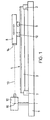
- a system is shown with which the can carry out the inventive method.
- This facility has a frame 1 on which there is a tensioning device 2 is located.
- a rail 3 in the tensioning device 2 a linear motion guide clamped on the Top side serves as a support for markings Magnetic tape 4 is attached.
- the magnetic tape 4 has a ferromagnetic material in the magnetic Markings in the form of north and south poles 5, 6 (Fig. 2a) to be introduced along an incremental track 7 and a parallel (not shown) Reference track are arranged that lead to a device for include a relative measurement method.
- a driven one Magnetizing cart 8 arranged with a magnetic Write 9 and a magnetic read head 10 is provided.
- the magnetizing carriage 8 is driven and parallel to Rail 3 movable.
- On the frame 1 is also in aligned approximately in the longitudinal direction of the rail 3
- Laser interferometer 12 as part of a measuring device arranged, the laser beam 13 as a mirror Reflection surface on an end face 14 of the Magnetizing 8 is directed.
- a magnetic induction B has the write head 9 - similar to a tape recorder head - one (Not shown) current-carrying coil.
- polarity or polarity reversal of the coil can be in the magnetizing material an orientation of the field lines are generated which either have a north or create a south pole.
- Position information and the known in the feed direction Distance between the reflection surface of the car 8 and the Read head 10 can refer to positions on magnetic tape 4 to a reference point 16 of the laser interferometer 12 exactly be determined. In principle, however, any Reference point can be selected because the absolute position of a marker is important but the length that results from the beginning and end of the respective marking results.
- the positions are determined at which the induction B picked up by the read head 10 is the same Is zero, i.e. the magnetic field strength changes direction. Such zero crossings 17, 18, 19, 20, 21 correspond to that Transition from one magnetic pole to the next.
- All Actual position data of all markings are together with the previously determined target position data in one EDP system, not shown, stored electronically.
- the Target position data have already been used to determine the Polarity reversal times of the coil of the write head 9 in the previously carried out marking step used. Subsequently the deviations of the measured positions from the Target positions are determined and also electronically saved.
- embodiments of the invention are also possible not zero crossings but other values or amounts of to detect physical quantities and based on them Determine and save correction values.
- the correction run of the Magnetizing trolley in the form of another Marking step of the same track For this, the Magnetizing carriage 8 via the magnetic tape 4, preferably in same way, i.e. especially with the same constant Feed speed and in the same feed direction, like driving in the first marking step.
- the magnetizing carriage with a other, possibly not constant speed moves. The only important thing is that exactly at One polarity reversal each time the specified positions are reached takes place. In the exemplary embodiment shown, the first three polarity reversals 17, 18, 19 at the right time took place, which is why the magnetic field strength change the intended positions.
- the second The marking step therefore differs so far not from the first marking step.
- the current is now only at reversed a route extended by 2A.
- the extension the distance refers to the current position of the Zero crossing 20 '.
- the resulting magnetization of track 7 represents curve 22 in FIG. 2b, while the magnetization carried out by the second marking step is represented by curve 22 '. 2b, the curves 22 and 22 'are only shown between the saturation ranges of the poles 6' and 5 ".
- the pole 5' following the pole 6 ' is shortened by the distance A.
- this second marking step all further deviations of the actual positions from the target positions of the zero crossings of the magnetizations (pole boundaries) are corrected.
- a second measuring step After completing the second marking step, in a second measuring step checks whether the resulting track itself all positions of the Zero crossings are located at the predetermined positions. If deviations are found again, one can a further marking step will be attempted, this too Eliminating difference. More measuring and Marking steps can follow until all Deviations correspond to the specified tolerances.
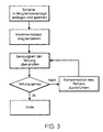
- FIG. 3 shows the marking method according to the invention for marking an incremental track on a rail Linear motion control in the form of a flow chart represented graphically.
Landscapes
- Physics & Mathematics (AREA)
- General Physics & Mathematics (AREA)
- Engineering & Computer Science (AREA)
- Signal Processing (AREA)
- Length Measuring Devices With Unspecified Measuring Means (AREA)
Applications Claiming Priority (2)
| Application Number | Priority Date | Filing Date | Title |
|---|---|---|---|
| CH240498 | 1998-12-03 | ||
| CH240498 | 1998-12-03 |
Publications (2)
| Publication Number | Publication Date |
|---|---|
| EP1006342A1 true EP1006342A1 (fr) | 2000-06-07 |
| EP1006342B1 EP1006342B1 (fr) | 2003-09-03 |
Family
ID=4233005
Family Applications (1)
| Application Number | Title | Priority Date | Filing Date |
|---|---|---|---|
| EP99123615A Expired - Lifetime EP1006342B1 (fr) | 1998-12-03 | 1999-11-26 | Procédé de marquage des pistes de mesure |
Country Status (3)
| Country | Link |
|---|---|
| US (1) | US6501262B1 (fr) |
| EP (1) | EP1006342B1 (fr) |
| DE (1) | DE59906848D1 (fr) |
Cited By (3)
| Publication number | Priority date | Publication date | Assignee | Title |
|---|---|---|---|---|
| DE102005049559A1 (de) * | 2005-10-12 | 2007-04-19 | Bogen Electronic Gmbh | Verfahren zum Aufbringen von Magnetkode auf magnetisierbare Schichten |
| DE102007063006A1 (de) | 2007-12-21 | 2009-06-25 | Baumer Holding Ag | Verfahren und Vorrichtung zur Herstellung einer Maßverkörperung für Positionsmesssysteme sowie Maßverkörperung |
| EP2447676A1 (fr) * | 2010-10-26 | 2012-05-02 | Bogen Electronic GmbH | Procédé de fabrication d'une échelle linéaire magnétique |
Families Citing this family (7)
| Publication number | Priority date | Publication date | Assignee | Title |
|---|---|---|---|---|
| WO2003004968A1 (fr) * | 2001-07-06 | 2003-01-16 | Inventio Ag | Procede et dispositif pour determiner la rectitude de rails de guidage |
| JP2006020415A (ja) * | 2004-07-01 | 2006-01-19 | Yamazaki Mazak Corp | リニアモータ用位置検出装置 |
| GB0522651D0 (en) * | 2005-11-07 | 2005-12-14 | Renishaw Plc | Scale and readhead system |
| WO2015108710A1 (fr) * | 2014-01-20 | 2015-07-23 | Apple Inc. | Détection de position de miroir utilisant la frange de distorsion de champs électriques |
| CN107966104B (zh) * | 2017-11-18 | 2019-06-21 | 北京工业大学 | 一种轴类零件长度测量装置 |
| US10908361B2 (en) | 2018-06-06 | 2021-02-02 | Apple Inc. | Capacitive position sensing for capacitive drive MEMS devices |
| GB2629438B (en) * | 2023-04-28 | 2025-10-08 | Airbus Operations Ltd | Method of checking the accuracy of a drilling robot |
Citations (3)
| Publication number | Priority date | Publication date | Assignee | Title |
|---|---|---|---|---|
| US4490914A (en) * | 1982-01-15 | 1985-01-01 | Dr. Johannes Heidenhain Gmbh | Error correction system for position measuring instruments |
| US4932131A (en) * | 1987-03-06 | 1990-06-12 | Renishaw Plc | Position determination apparatus |
| EP0395374A1 (fr) * | 1989-04-28 | 1990-10-31 | Renishaw plc | Echelle métrologique optique |
Family Cites Families (1)
| Publication number | Priority date | Publication date | Assignee | Title |
|---|---|---|---|---|
| US5949685A (en) * | 1997-06-03 | 1999-09-07 | The Boeing Company | Real-time orientation of machine media to improve machine accuracy |
-
1999
- 1999-11-26 DE DE59906848T patent/DE59906848D1/de not_active Expired - Lifetime
- 1999-11-26 EP EP99123615A patent/EP1006342B1/fr not_active Expired - Lifetime
- 1999-12-01 US US09/451,703 patent/US6501262B1/en not_active Expired - Lifetime
Patent Citations (3)
| Publication number | Priority date | Publication date | Assignee | Title |
|---|---|---|---|---|
| US4490914A (en) * | 1982-01-15 | 1985-01-01 | Dr. Johannes Heidenhain Gmbh | Error correction system for position measuring instruments |
| US4932131A (en) * | 1987-03-06 | 1990-06-12 | Renishaw Plc | Position determination apparatus |
| EP0395374A1 (fr) * | 1989-04-28 | 1990-10-31 | Renishaw plc | Echelle métrologique optique |
Cited By (4)
| Publication number | Priority date | Publication date | Assignee | Title |
|---|---|---|---|---|
| DE102005049559A1 (de) * | 2005-10-12 | 2007-04-19 | Bogen Electronic Gmbh | Verfahren zum Aufbringen von Magnetkode auf magnetisierbare Schichten |
| DE102007063006A1 (de) | 2007-12-21 | 2009-06-25 | Baumer Holding Ag | Verfahren und Vorrichtung zur Herstellung einer Maßverkörperung für Positionsmesssysteme sowie Maßverkörperung |
| WO2009083043A3 (fr) * | 2007-12-21 | 2009-09-24 | Baumer Holding Ag | Procédé et dispositif de réalisation d'une mesure matérialisée pour des systèmes de mesure de position et mesure matérialisée |
| EP2447676A1 (fr) * | 2010-10-26 | 2012-05-02 | Bogen Electronic GmbH | Procédé de fabrication d'une échelle linéaire magnétique |
Also Published As
| Publication number | Publication date |
|---|---|
| US6501262B1 (en) | 2002-12-31 |
| EP1006342B1 (fr) | 2003-09-03 |
| DE59906848D1 (de) | 2003-10-09 |
Similar Documents
| Publication | Publication Date | Title |
|---|---|---|
| DE4319322C2 (de) | Positionsmeßeinrichtung | |
| DE4408623A1 (de) | Magnetischer Positionssensor | |
| EP0555507A1 (fr) | Capteur de position | |
| DE3245914C1 (de) | Messeinrichtung | |
| EP0085148B1 (fr) | Dispositif pour la rectification des erreurs dans des systèmes de mesure de position | |
| DE3325353A1 (de) | Positionssensor | |
| EP1006342B1 (fr) | Procédé de marquage des pistes de mesure | |
| EP2846126A1 (fr) | Dispositif de mesure et procédé de mesure de la position de corps | |
| DE3208591C2 (de) | Digitales elektrisches Längen- oder Winkelmeßsystem | |
| EP1748283A2 (fr) | Détecteur sensible au champ magnétique | |
| EP1770373A1 (fr) | Dispositif de mesure de la position absolue | |
| WO2003105556A1 (fr) | Roue transporteuse a courroie a elements, systeme transporteur a courroie a elements et procede d'exploitation d'un systeme transporteur a courroie a elements | |
| DE3245357C2 (de) | Inkrementale Meßeinrichtung | |
| DE19506104A1 (de) | Magnetisches Meßsystem | |
| EP0038070A2 (fr) | Disposition d'analyse de documents revêtus de signes graphiques | |
| DE10123539B4 (de) | Magnetische Längenmessvorrichtung | |
| DE19800774A1 (de) | Verfahren und magnetische Maßverkörperung zur Generierung eines Referenzsignals sowie Herstellungsverfahren für eine solche magnetische Maßverkörperung | |
| DE10210326A1 (de) | Magnetisieren von magnetischen Meßkörpern | |
| DE19643538A1 (de) | Vorrichtung zur Längenmessung | |
| DE2740563C2 (de) | Mehrpoliger permanentmagnetischer Löschkopf sowie Verfahren und Vorrichtung zu seiner Magnetisierung | |
| EP0626299A1 (fr) | Dispositif pour détecter la position d'un véhicule, déplaçable le long d'un rail | |
| EP0374294A1 (fr) | Dispositif de transmission d'information à un véhicule à voie de guidage | |
| DE3926328A1 (de) | Vorrichtung zum messen von laengen, winkeln und dergleichen | |
| DE3509838C2 (fr) | ||
| DE2137631B2 (de) | Verfahren und vorrichtung zur selbsttaetigen spurfuehrung von gleislosen fahrzeugen |
Legal Events
| Date | Code | Title | Description |
|---|---|---|---|
| PUAI | Public reference made under article 153(3) epc to a published international application that has entered the european phase |
Free format text: ORIGINAL CODE: 0009012 |
|
| AK | Designated contracting states |
Kind code of ref document: A1 Designated state(s): CH DE FR IT LI |
|
| AX | Request for extension of the european patent |
Free format text: AL;LT;LV;MK;RO;SI |
|
| 17P | Request for examination filed |
Effective date: 20000808 |
|
| AKX | Designation fees paid |
Free format text: CH DE FR IT LI |
|
| GRAH | Despatch of communication of intention to grant a patent |
Free format text: ORIGINAL CODE: EPIDOS IGRA |
|
| GRAS | Grant fee paid |
Free format text: ORIGINAL CODE: EPIDOSNIGR3 |
|
| GRAA | (expected) grant |
Free format text: ORIGINAL CODE: 0009210 |
|
| AK | Designated contracting states |
Kind code of ref document: B1 Designated state(s): CH DE FR IT LI |
|
| PG25 | Lapsed in a contracting state [announced via postgrant information from national office to epo] |
Ref country code: IT Free format text: LAPSE BECAUSE OF FAILURE TO SUBMIT A TRANSLATION OF THE DESCRIPTION OR TO PAY THE FEE WITHIN THE PRESCRIBED TIME-LIMIT;WARNING: LAPSES OF ITALIAN PATENTS WITH EFFECTIVE DATE BEFORE 2007 MAY HAVE OCCURRED AT ANY TIME BEFORE 2007. THE CORRECT EFFECTIVE DATE MAY BE DIFFERENT FROM THE ONE RECORDED. Effective date: 20030903 Ref country code: FR Free format text: LAPSE BECAUSE OF FAILURE TO SUBMIT A TRANSLATION OF THE DESCRIPTION OR TO PAY THE FEE WITHIN THE PRESCRIBED TIME-LIMIT Effective date: 20030903 |
|
| REG | Reference to a national code |
Ref country code: CH Ref legal event code: EP |
|
| REF | Corresponds to: |
Ref document number: 59906848 Country of ref document: DE Date of ref document: 20031009 Kind code of ref document: P |
|
| REG | Reference to a national code |
Ref country code: CH Ref legal event code: NV Representative=s name: PATMED AG |
|
| PLBE | No opposition filed within time limit |
Free format text: ORIGINAL CODE: 0009261 |
|
| STAA | Information on the status of an ep patent application or granted ep patent |
Free format text: STATUS: NO OPPOSITION FILED WITHIN TIME LIMIT |
|
| 26N | No opposition filed |
Effective date: 20040604 |
|
| EN | Fr: translation not filed | ||
| PGFP | Annual fee paid to national office [announced via postgrant information from national office to epo] |
Ref country code: DE Payment date: 20181120 Year of fee payment: 20 |
|
| PGFP | Annual fee paid to national office [announced via postgrant information from national office to epo] |
Ref country code: CH Payment date: 20190226 Year of fee payment: 20 |
|
| REG | Reference to a national code |
Ref country code: DE Ref legal event code: R071 Ref document number: 59906848 Country of ref document: DE |
|
| REG | Reference to a national code |
Ref country code: CH Ref legal event code: PL |