EP1006676B1 - Rahmensynchronisation in Raum-Zeit kodierter Sendeantennendiversität - Google Patents
Rahmensynchronisation in Raum-Zeit kodierter Sendeantennendiversität Download PDFInfo
- Publication number
- EP1006676B1 EP1006676B1 EP99203292A EP99203292A EP1006676B1 EP 1006676 B1 EP1006676 B1 EP 1006676B1 EP 99203292 A EP99203292 A EP 99203292A EP 99203292 A EP99203292 A EP 99203292A EP 1006676 B1 EP1006676 B1 EP 1006676B1
- Authority
- EP
- European Patent Office
- Prior art keywords
- symbol
- signals
- signal
- estimate
- producing
- Prior art date
- Legal status (The legal status is an assumption and is not a legal conclusion. Google has not performed a legal analysis and makes no representation as to the accuracy of the status listed.)
- Expired - Lifetime
Links
- 238000005562 fading Methods 0.000 claims description 10
- 238000004891 communication Methods 0.000 claims description 9
- 238000000034 method Methods 0.000 claims description 8
- 238000010295 mobile communication Methods 0.000 claims description 6
- 238000010586 diagram Methods 0.000 description 10
- 230000005540 biological transmission Effects 0.000 description 8
- WABPQHHGFIMREM-OIOBTWANSA-N lead-204 Chemical compound [204Pb] WABPQHHGFIMREM-OIOBTWANSA-N 0.000 description 2
- WABPQHHGFIMREM-BJUDXGSMSA-N lead-206 Chemical compound [206Pb] WABPQHHGFIMREM-BJUDXGSMSA-N 0.000 description 2
- 230000000996 additive effect Effects 0.000 description 1
- 230000001427 coherent effect Effects 0.000 description 1
- 238000001514 detection method Methods 0.000 description 1
- 230000003292 diminished effect Effects 0.000 description 1
- 230000010363 phase shift Effects 0.000 description 1
Images
Classifications
-
- H—ELECTRICITY
- H04—ELECTRIC COMMUNICATION TECHNIQUE
- H04B—TRANSMISSION
- H04B1/00—Details of transmission systems, not covered by a single one of groups H04B3/00 - H04B13/00; Details of transmission systems not characterised by the medium used for transmission
- H04B1/69—Spread spectrum techniques
- H04B1/707—Spread spectrum techniques using direct sequence modulation
- H04B1/7073—Synchronisation aspects
- H04B1/7075—Synchronisation aspects with code phase acquisition
- H04B1/7077—Multi-step acquisition, e.g. multi-dwell, coarse-fine or validation
-
- H—ELECTRICITY
- H04—ELECTRIC COMMUNICATION TECHNIQUE
- H04B—TRANSMISSION
- H04B7/00—Radio transmission systems, i.e. using radiation field
- H04B7/02—Diversity systems; Multi-antenna system, i.e. transmission or reception using multiple antennas
- H04B7/04—Diversity systems; Multi-antenna system, i.e. transmission or reception using multiple antennas using two or more spaced independent antennas
- H04B7/08—Diversity systems; Multi-antenna system, i.e. transmission or reception using multiple antennas using two or more spaced independent antennas at the receiving station
- H04B7/0837—Diversity systems; Multi-antenna system, i.e. transmission or reception using multiple antennas using two or more spaced independent antennas at the receiving station using pre-detection combining
- H04B7/0842—Weighted combining
- H04B7/0845—Weighted combining per branch equalization, e.g. by an FIR-filter or RAKE receiver per antenna branch
-
- H—ELECTRICITY
- H04—ELECTRIC COMMUNICATION TECHNIQUE
- H04B—TRANSMISSION
- H04B1/00—Details of transmission systems, not covered by a single one of groups H04B3/00 - H04B13/00; Details of transmission systems not characterised by the medium used for transmission
- H04B1/69—Spread spectrum techniques
- H04B1/707—Spread spectrum techniques using direct sequence modulation
- H04B1/7097—Interference-related aspects
- H04B1/711—Interference-related aspects the interference being multi-path interference
-
- H—ELECTRICITY
- H04—ELECTRIC COMMUNICATION TECHNIQUE
- H04B—TRANSMISSION
- H04B7/00—Radio transmission systems, i.e. using radiation field
- H04B7/02—Diversity systems; Multi-antenna system, i.e. transmission or reception using multiple antennas
-
- H—ELECTRICITY
- H04—ELECTRIC COMMUNICATION TECHNIQUE
- H04B—TRANSMISSION
- H04B7/00—Radio transmission systems, i.e. using radiation field
- H04B7/02—Diversity systems; Multi-antenna system, i.e. transmission or reception using multiple antennas
- H04B7/04—Diversity systems; Multi-antenna system, i.e. transmission or reception using multiple antennas using two or more spaced independent antennas
- H04B7/06—Diversity systems; Multi-antenna system, i.e. transmission or reception using multiple antennas using two or more spaced independent antennas at the transmitting station
-
- H—ELECTRICITY
- H04—ELECTRIC COMMUNICATION TECHNIQUE
- H04L—TRANSMISSION OF DIGITAL INFORMATION, e.g. TELEGRAPHIC COMMUNICATION
- H04L1/00—Arrangements for detecting or preventing errors in the information received
- H04L1/02—Arrangements for detecting or preventing errors in the information received by diversity reception
- H04L1/06—Arrangements for detecting or preventing errors in the information received by diversity reception using space diversity
- H04L1/0618—Space-time coding
- H04L1/0625—Transmitter arrangements
-
- H—ELECTRICITY
- H04—ELECTRIC COMMUNICATION TECHNIQUE
- H04B—TRANSMISSION
- H04B1/00—Details of transmission systems, not covered by a single one of groups H04B3/00 - H04B13/00; Details of transmission systems not characterised by the medium used for transmission
- H04B1/69—Spread spectrum techniques
- H04B1/707—Spread spectrum techniques using direct sequence modulation
Definitions
- This invention relates to wideband code division multiple access (WCDMA) for a communication system and more particularly to space time block coded transmit antenna diversity for frame synchronization of WCDMA signals.
- WCDMA wideband code division multiple access
- CDMA code division multiple access
- FDMA frequency division multiple access
- TDMA time division multiple access
- WCDMA wideband code division multiple access
- These WCDMA systems are coherent communications systems with pilot symbol assisted channel estimation schemes. These pilot symbols are transmitted as quadrature phase shift keyed (QPSK) known data in predetermined time frames to any receivers within range.
- QPSK quadrature phase shift keyed
- the frames may propagate in a discontinuous transmission (DTX) mode.
- DTX discontinuous transmission
- voice traffic transmission of user data occurs when the user speaks, but no data symbol transmission occurs when the user is silent.
- packet data the user data may be transmitted only when packets are ready to be sent.
- the frames are subdivided into sixteen equal time slots of 0.625 milliseconds each.
- Each time slot is further subdivided into equal symbol times.
- each time slot includes twenty symbol times.
- Each frame includes pilot symbols as well as other control symbols such as transmit power control (TPC) symbols and rate information (RI) symbols. These control symbols include multiple bits otherwise known as chips to distinguish them from data bits.
- T C transmit power control
- RI rate information
- OTD orthogonal transmit diversity
- TSTD time switched time diversity
- Both OTD and TSTD systems have similar performance. Both use multiple transmit antennas to provide some diversity against fading, particularly at low Doppler rates and when there are insufficient paths for the rake receiver. Both OTD and TSTD systems, however, fail to exploit the extra path diversity that is possible for open loop systems.
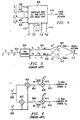
- the OTD encoder circuit of FIG. 5 receives symbols S 1 and S 2 on lead 500 and produces output signals on leads 504 and 506 for transmission by first and second antennas, respectively. These transmitted signals are received by a despreader input circuit (not shown).
- the despreader circuit sums received chip signals over a respective symbol time to produce first and second output signals R j 1 and R j 2 on leads 620 and 622 as in equations [1-2], respectively.
- the OTD phase correction circuit of FIG. 6 receives the output signals R j 1 and R j 2 corresponding to the j th of L multiple signal paths.
- the phase correction circuit produces soft outputs or signal estimates S 1 and S 2 for symbols S 1 and S 2 at leads 616 and 618 as shown in equations [3-4], respectively.
- Equations [3-4] show that the OTD method provides a single channel estimate ⁇ for each path j .
- a similar analysis for the TSTD system yields the same result.
- the OTD and TSTD methods therefore, are limited to a path diversity of L . This path diversity limitation fails to exploit the extra path diversity that is possible for open loop systems as will be explained in detail.
- a circuit is designed with a correction circuit coupled to receive a first estimate signal, a second estimate signal, and a plurality of input signals from an external source along plural signal paths.
- the plurality of input signals includes a first and a second input signal.
- the correction circuit produces a first symbol estimate in response to the first and second estimate signals and the first and second input signals.
- the correction circuit produces a second symbol estimate in response to the first and second estimate signals and the first and second input signals.
- a combining circuit is coupled to receive a plurality of first symbol estimates including the first symbol estimate and a plurality of second symbol estimates including the second symbol estimate.
- the combining circuit produces a first symbol signal in response to the plurality of first symbol estimates and a second symbol signal in response to the plurality of second symbol estimates.
- a synchronization circuit is coupled to receive the first and second symbol signals and a first known symbol and a second known symbol.
- the synchronization circuit produces a synchronization signal in response to an approximate match between the first symbol signal and the first known symbol and between the second symbol signal and the second known symbol.
- the present invention improves frame synchronization by providing at least 2L diversity over time and space. No additional transmit power or bandwidth is required. Power is balanced across multiple antennas.
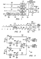
- FIG. 1 there is a simplified block diagram of a typical transmitter using Space Time Transit Diversity (STTD) of the present invention.
- the transmitter circuit receives pilot symbols, TPC symbols, RI symbols and data symbols on leads 100, 102, 104 and 106, respectively.
- Each of the symbols is encoded by a respective STTD encoder as will be explained in detail.
- Each STTD encoder produces two output signals that are applied to multiplex circuit 120.
- the multiplex circuit 120 produces each encoded symbol in a respective symbol time of a frame.
- a serial sequence of symbols in each frame is simultaneously applied to each respective multiplier circuit 124 and 126.
- a channel orthogonal code C m is multiplied by each symbol to provide a unique signal for a designated receiver.
- the STTD encoded frames are then applied to antennas 128 and 130 for transmission.
- FIG. 2 there is a block diagram showing signal flow in an STTD encoder of the present invention that may be used with the transmitter of FIG. 1 for pilot symbol encoding.
- the pilot symbols are predetermined control signals that may be used for channel estimation and other functions as will be described in detail. Operation of the STTD encoder 112 will be explained with reference to TABLE 1.
- the STTD encoder receives pilot symbol 11 at symbol time T , pilot symbol S 1 at symbol time 2 T , pilot symbol 11 at symbol time 3T and pilot symbol S 2 at symbol time 4T on lead 100 for each of sixteen time slots of a frame.
- the STTD encoder produces a sequence of four pilot symbols for each of two antennas corresponding to leads 204 and 206, respectively, for each of the sixteen time slots of TABLE 1.
- the STTD encoder produces pilot symbols B 1 , S 1 , B 2 and S 2 at symbol times T -4 T , respectively, for a first antenna at lead 204.
- the STTD encoder simultaneously produces pilot symbols B 1 , - S 2 * , - B 2 and S 1 * at symbol times T-4T, respectively, at lead 206 for a second antenna.
- Each symbol includes two bits representing a real and imaginary component.
- An asterisk indicates a complex conjugate operation or sign change of the imaginary part of the symbol. Pilot symbol values for the first time slot for the first antenna at lead 204, therefore, are 11, 11, 11 and 11.
- Corresponding pilot symbols for the second antenna at lead 206 are 11, 01, 00 and 10.
- the bit signals r j ( i + ⁇ j ) of these symbols are transmitted serially along respective paths 208 and 210. Each bit signal of a respective symbol is subsequently received at a remote mobile antenna 212 after a transmit time r corresponding to the j th path.
- the signals propagate to a despreader input circuit (not shown) where they are summed over each respective symbol time to produce input signals R j 1 , R j 2 , R j 3 and R j 4 corresponding to the four pilot symbol time slots and the j th of L multiple signal paths as previously described.
- Received signal R j 1 is produced by pilot symbols ( B 1 , B 1 ) having a constant value (11,11) at symbol time T for all time slots.
- the received signal is equal to the sum of respective Rayleigh fading parameters corresponding to the first and second antennas.
- received signal R j 3 is produced by pilot symbols ( B 2 , - B 2 ) having a constant value (11,00) at symbol time 3T for all time slots.
- Channel estimates for the Rayleigh fading parameters corresponding to the first and second antennas therefore, are readily obtained from input signals R j 1 and R j 3 as in equations [9] and [10].
- R j 1 ⁇ j 1 + ⁇ j 2
- R j 2 ⁇ j 1 ⁇ S 1 + ⁇ j 2 ⁇ S 2 *
- R j 3 ⁇ j 1 - ⁇ j 2
- ⁇ j 2 R j 1 - R j 3 / 2
- FIG. 3 there is a schematic diagram of a phase correction circuit of the present invention that may be used with a remote mobile receiver.
- This phase correction circuit receives input signals R j 2 and R j 4 on leads 324 and 326 at symbol times 2 T and 4 T, respectively. Each input signal has a value determined by the transmitted pilot symbols as shown in equations [6] and [8], respectively.
- the phase correction circuit receives a complex conjugate of a channel estimate of a Rayleigh fading parameter ⁇ j 1 * corresponding to the first antenna on lead 302 and a channel estimate of another Rayleigh fading parameter ⁇ j 2 corresponding to the second antenna on lead 306.
- Complex conjugates of the input signals are produced by circuits 308 and 330 at leads 310 and 322, respectively.
- FIG. 4 there is a block diagram of a frame synchronization circuit that may be used with STTD of the present invention.
- the circuit compares soft symbol signals S and S 2 , at leads 400-406 to the complex conjugates of known pilot symbols S 1, k and S 2, k at leads 410-416 for each of the sixteen time slots as in equation [15].
- This comparison produces an approximate match when all soft symbol signals are multiplied by their respective known complex conjugate symbols, thereby producing a real result having a maximum value.
- the synchronization circuit produces frame synchronization signal FS on lead 418 in response to this real result.
- the reliability of this approximate match is substantially improved in view of the superior soft symbol signals obtained through the additional diversity provided by STTD.
- pilot symbol patterns of TABLE 1 are suitable for data rates of 16, 32, 64 and 128 KSPS having four pilot symbols in each time slot. Other patterns produce a similar result.
- the pattern of TABLE 2, for example, applied to the second antenna produces the same result.
- R j 1 ⁇ j 1 ⁇ B 1 + ⁇ j 2 ⁇ B 1 *
- TABLE 3 and TABLE 4 give the pilot symbol patterns for data rates with two and eight pilot symbols in each time slot for the first and second antennas, respectively.
- TABLE 5 and TABLE 6 give the pilot symbol patterns for data rates with sixteen pilot symbols in each time slot for the first and second antennas, respectively.
- TABLE 3 8 KSPS 256, 512, 1024 KSPS SLOT 0 1 0 1 2 3 4 5 6 7 1 11 11 11 11 11 11 11 11 10 2 11 11 11 10 11 10 11 10 11 10 11 01 3 11 10 11 10 11 01 11 11 11 01 4 11 01 11 11 11 01 11 00 11 10 5 11 10 11 11 11 11 11 00 11 01 11 10 6 11 10 11 11 11 11 11 11 11 11 11 11 11 10 7 11 01 11 10 11 11 11 11 01 11 10 8 11 00 11 01 11 00 11 10 11 00 9 11 00 11 11 11 10 11 00 11 01 10 11 10 11 01 11 11 11 11 11 00 11 10 11 10 11 11 11 10 12 11 11 11 01 11 10 11 10 11 00 13 11 10 11 10 11 01 11 11 11 11 10 14 11 11 11 11 00 11 10 11 10 11 00 15 11 00 11 01 11 10 11 00 11 00 16
Landscapes
- Engineering & Computer Science (AREA)
- Computer Networks & Wireless Communication (AREA)
- Signal Processing (AREA)
- Radio Transmission System (AREA)
- Mobile Radio Communication Systems (AREA)
- Synchronisation In Digital Transmission Systems (AREA)
- Time-Division Multiplex Systems (AREA)
Claims (7)
- Mobilkommunikationssystem, mit:einer mobilen Antenne (212), die so beschaffen ist, dass sie während einer vorgegebenen Zeitdauer von einer externen Quelle auf mehreren Signalwegen mehrere Gruppen von Signalen empfängt, wobei die Gruppen zeitlich gleichmäßig beabstandet sind;einer Eingangsschaltung zum Empfangen der mehreren Gruppen von Signalen von der mobilen Antenne, wobei die Eingangsschaltung so beschaffen ist, dass sie mehrere Eingangssignale erzeugt, die ein erstes Eingangssignal und ein zweites Eingangssignal (Rj 1, Rj 2) enthalten, wobei jedes Eingangssignal einer entsprechenden Gruppe von Signalen entspricht, die auf verschiedenen Signalwegen der mehreren Signalwege empfangen werden, und ein erstes bzw. ein zweites Kanalschätzsignal, die dem Empfang auf den verschiedenen Wegen entsprechen, ableitet;einer Korrekturschaltung (350), die so angeschlossen ist, dass sie das erste Kanalschätzsignal, das zweite Kanalschätzsignal und das erste und das zweite Eingangssignal empfängt, wobei die Korrekturschaltung so beschaffen ist, dass sie eine erste Symbolschätzung als eine erste Kombination aus dem ersten und dem zweiten Eingangssignal, die korrigiert sind, in Abhängigkeit von dem ersten und dem zweiten Kanalschätzsignal erzeugt, wobei die Korrekturschaltung ferner so beschaffen ist, dass sie eine zweite Symbolschätzung als eine von der ersten Kombination verschiedene zweite Kombination aus dem ersten und dem zweiten Eingangssignal in Abhängigkeit von dem ersten und dem zweiten Kanalschätzsignal erzeugt;einer Kombinationsschaltung zum Empfangen mehrerer erster Symbolschätzungen, die die erste Symbolschätzung enthalten, und mehrerer zweiter Symbolschätzungen, die die zweite Symbolschätzung enthalten, wobei die Kombinationsschaltung so beschaffen ist, dass sie ein erstes Symbolsignal durch Kombinieren der ersten Symbolschätzungen erzeugt und ein zweites Symbolsignal durch Kombinieren der zweiten Symbolschätzungen erzeugt; undeiner Synchronisationsschaltung (408) zum Empfangen des ersten und des zweiten Symbolsignals (400-406) und eines ersten bekannten Symbols sowie eines zweiten bekannten Symbols (410-416), wobei die Synchronisationsschaltung so beschaffen ist, dass sie das erste Symbolsignal mit dem ersten bekannten Symbol und das zweite Symbolsignal mit dem zweiten bekannten Symbol vergleicht und in Reaktion auf eine Übereinstimmung zwischen dem ersten Symbolsignal und dem ersten bekannten Symbol sowie zwischen dem zweiten Symbolsignal und dem zweiten bekannten Symbol ein Synchronisationssignal (418) erzeugt.
- Mobilkommunikationssystem nach Anspruch 1, ferner mit einer Schätzschaltung zum Empfangen wenigstens eines ersten vorgegebenen Signals und eines zweiten vorgegebenen Signals von der externen Quelle, wobei sowohl das erste als auch das zweite vorgegebene Signal jeweils einen vorgegebenen Wert hat, wobei die Schätzschaltung so beschaffen ist, dass sie das erste Schätzsignal und das zweite Schätzsignal in Reaktion auf das erste und das zweite vorgegebene Signal erzeugt.
- Mobilkommunikationssystem nach Anspruch 2, wobei sowohl das erste als auch das zweite vorgegebene Signal ein Pilotsymbol ist.
- Mobilkommunikationssystem nach einem vorhergehenden Anspruch, wobei sowohl das erste als auch das zweite Schätzsignal eine Rayleigh-Fading-Parameterschätzung ist.
- Verfahren zum Verarbeiten von Signalen in einer Kommunikationsschaltungsanordnung, wobei das Verfahren umfasst:Empfangen mehrerer Gruppen vorgegebener Signale während einer vorgegebenen Zeitdauer von einer externen Quelle auf mehreren Signalwegen, wobei die Gruppen zeitlich gleichmäßig beabstandet sind;Erzeugen mehrerer Eingangssignale, die ein erstes Eingangssignal und ein zweites Eingangssignal (Rj 1, Rj 2) enthalten, wobei jedes Eingangssignal einer entsprechenden Gruppe von Signalen entspricht, die auf verschiedenen Signalwegen der mehreren Signalwege empfangen werden, und Ableiten eines ersten bzw. eines zweiten Kanalschätzsignals, die dem Empfang auf den verschiedenen Wegen entsprechen;Erzeugen einer ersten Symbolschätzung als eine erste Kombination aus dem ersten und dem zweiten Eingangssignal, die korrigiert sind, in Abhängigkeit von dem ersten und dem zweiten Kanalschätzsignal;Erzeugen einer zweiten Symbolschätzung als eine von der ersten Kombination verschiedene zweite Kombination aus dem ersten und dem zweiten Eingangssignal, die korrigiert sind, in Abhängigkeit von dem ersten und dem zweiten Kanalschätzsignal;Wiederholen der beiden obigen Schritte, um mehrere erste und zweite Symbolschätzungen zu erzeugen;Erzeugen eines ersten Symbolsignals durch Kombinieren der ersten Symbolschätzungen und Erzeugen eines zweiten Symbolsignals durch Kombinieren der zweiten Symbolschätzungen;Vergleichen des ersten Symbolsignals mit einem bekannten ersten Symbol;Vergleichen des zweiten Symbolsignals mit einem bekannten zweiten Symbol; undErzeugen eines Synchronisationssignals in Reaktion auf die Vergleichsschritte.
- Verfahren zum Verarbeiten von Signalen nach Anspruch 5, das ferner die folgenden Schritte umfasst:Erzeugen eines ersten der wenigstens zwei Schätzsignale aus einer Summe aus wenigstens zwei vorgegebenen Signalen jeder entsprechenden Gruppe; undErzeugen eines zweiten der wenigstens zwei Schätzsignale aus einer Differenz zwischen den wenigstens zwei anderen Signalen jeder entsprechenden Gruppe.
- Verfahren zum Verarbeiten von Signalen nach Anspruch 5 oder Anspruch 6, wobei der Schritt des Vergleichens der mehreren ersten Symbolsignale mit mehreren bekannten ersten Symbolen das Vergleichen jedes bekannten ersten Symbols mit jedem ersten Symbolsignal umfasst und wobei der Schritt des Vergleichens der mehreren zweiten Symbolsignalen mit mehreren bekannten zweiten Symbolen das Vergleichen jedes bekannten zweiten Symbols mit jedem zweiten Symbolsignal umfasst.
Applications Claiming Priority (5)
| Application Number | Priority Date | Filing Date | Title |
|---|---|---|---|
| US10338398P | 1998-10-07 | 1998-10-07 | |
| US103383P | 1998-10-07 | ||
| US103383 | 1998-11-19 | ||
| US09/195,942 US6356605B1 (en) | 1998-10-07 | 1998-11-19 | Frame synchronization in space time block coded transmit antenna diversity for WCDMA |
| US195942 | 1998-11-19 |
Publications (3)
| Publication Number | Publication Date |
|---|---|
| EP1006676A2 EP1006676A2 (de) | 2000-06-07 |
| EP1006676A3 EP1006676A3 (de) | 2004-05-06 |
| EP1006676B1 true EP1006676B1 (de) | 2008-01-16 |
Family
ID=26800404
Family Applications (1)
| Application Number | Title | Priority Date | Filing Date |
|---|---|---|---|
| EP99203292A Expired - Lifetime EP1006676B1 (de) | 1998-10-07 | 1999-10-07 | Rahmensynchronisation in Raum-Zeit kodierter Sendeantennendiversität |
Country Status (5)
| Country | Link |
|---|---|
| US (1) | US6356605B1 (de) |
| EP (1) | EP1006676B1 (de) |
| JP (2) | JP4729155B2 (de) |
| KR (1) | KR100756679B1 (de) |
| DE (1) | DE69937987T2 (de) |
Families Citing this family (24)
| Publication number | Priority date | Publication date | Assignee | Title |
|---|---|---|---|---|
| US6724828B1 (en) * | 1999-01-19 | 2004-04-20 | Texas Instruments Incorporated | Mobile switching between STTD and non-diversity mode |
| EP1133071B1 (de) * | 1999-02-25 | 2014-05-21 | Texas Instruments Incorporated | Raum-Zeit-Sendediversität für TDD/WCDMA Systeme |
| US6775260B1 (en) | 1999-02-25 | 2004-08-10 | Texas Instruments Incorporated | Space time transmit diversity for TDD/WCDMA systems |
| KR100294711B1 (ko) * | 1999-03-15 | 2001-07-12 | 서평원 | 최적의 파일럿 심볼을 이용한 프레임 동기 방법 |
| US7496132B2 (en) * | 1999-03-15 | 2009-02-24 | Kg Electronics Inc. | Pilot signals for synchronization and/or channel estimation |
| US7643540B2 (en) * | 1999-03-15 | 2010-01-05 | Lg Electronics Inc. | Pilot signals for synchronization and/or channel estimation |
| US6891815B1 (en) * | 1999-03-15 | 2005-05-10 | Young-Joon Song | Pilot signals for synchronization and/or channel estimation |
| US6804264B1 (en) * | 1999-03-15 | 2004-10-12 | Lg Information & Communications, Ltd. | Pilot signals for synchronization and/or channel estimation |
| US7012906B1 (en) * | 1999-03-15 | 2006-03-14 | Lg Information & Communications, Ltd. | Pilot signals for synchronization and/or channel estimation |
| US6791960B1 (en) | 1999-03-15 | 2004-09-14 | Lg Information And Communications, Ltd. | Pilot signals for synchronization and/or channel estimation |
| US6721299B1 (en) * | 1999-03-15 | 2004-04-13 | Lg Information & Communications, Ltd. | Pilot signals for synchronization and/or channel estimation |
| US7006581B2 (en) * | 2000-05-25 | 2006-02-28 | Vigil Armando J | Method for demodulating a digital signal subjected to multipath propagation impairment and an associated receiver |
| US7154958B2 (en) * | 2000-07-05 | 2006-12-26 | Texas Instruments Incorporated | Code division multiple access wireless system with time reversed space time block transmitter diversity |
| US7065156B1 (en) * | 2000-08-31 | 2006-06-20 | Nokia Mobile Phones Ltd. | Hopped delay diversity for multiple antenna transmission |
| EP1340331B1 (de) * | 2000-11-22 | 2007-01-24 | Nortel Networks Limited | Verfahren und vorrichtung für turbo raum-zeit trelliskodierung |
| US7113745B2 (en) * | 2001-02-21 | 2006-09-26 | Ericsson Inc. | Method to achieve diversity in a communication network |
| KR100698199B1 (ko) * | 2001-06-05 | 2007-03-22 | 엘지전자 주식회사 | 전송 안테나 다이버시티 방법 |
| JP3530164B2 (ja) | 2001-10-16 | 2004-05-24 | 松下電器産業株式会社 | Sttdデコード方法およびsttdデコーダ |
| US7173992B2 (en) * | 2001-12-11 | 2007-02-06 | Sasken Communication Technologies Limited | Method for synchronization in wireless systems using receive diversity |
| CN1170374C (zh) * | 2002-06-20 | 2004-10-06 | 大唐移动通信设备有限公司 | 一种适用于频率选择性衰落信道的空时编译码方法 |
| CN100426707C (zh) * | 2003-01-03 | 2008-10-15 | 华为技术有限公司 | 一种闭环发射分集系统中反馈信号的处理方法及其装置 |
| WO2005078978A1 (ja) | 2004-02-13 | 2005-08-25 | Matsushita Electric Industrial Co., Ltd. | 送信装置、受信装置及び無線通信方法 |
| RU2491717C2 (ru) * | 2010-05-04 | 2013-08-27 | Попик Павел Иванович | Способ повышения уровня (отношения) сигнал-шум при применении "принципа затухания помехи" |
| GB201317525D0 (en) | 2013-10-03 | 2013-11-20 | Fujifilm Mfg Europe Bv | Membranes |
Family Cites Families (10)
| Publication number | Priority date | Publication date | Assignee | Title |
|---|---|---|---|---|
| US5228054A (en) | 1992-04-03 | 1993-07-13 | Qualcomm Incorporated | Power-of-two length pseudo-noise sequence generator with fast offset adjustment |
| US5481572A (en) * | 1994-08-02 | 1996-01-02 | Ericsson Inc. | Method of and apparatus for reducing the complexitiy of a diversity combining and sequence estimation receiver |
| JP2689926B2 (ja) * | 1994-12-05 | 1997-12-10 | 日本電気株式会社 | ダイバーシティ受信機 |
| JP3582924B2 (ja) * | 1996-01-19 | 2004-10-27 | 松下電器産業株式会社 | 復調装置 |
| JPH1051354A (ja) * | 1996-05-30 | 1998-02-20 | N T T Ido Tsushinmo Kk | Ds−cdma伝送方法 |
| US5767738A (en) * | 1996-10-21 | 1998-06-16 | Motorola, Inc. | Apparatus and method for demodulating a modulated signal |
| JPH10164652A (ja) * | 1996-12-03 | 1998-06-19 | Matsushita Electric Ind Co Ltd | 移動通信装置 |
| JPH10200508A (ja) * | 1997-01-14 | 1998-07-31 | Sony Corp | 無線システムの端末装置及びサーチ方法 |
| US6226315B1 (en) * | 1998-03-09 | 2001-05-01 | Texas Instruments Incorporated | Spread-spectrum telephony with accelerated code acquisition |
| US6166622A (en) * | 1998-10-28 | 2000-12-26 | Texas Instruments Incorporated | Time slot structure for improved TPC estimation in WCDMA |
-
1998
- 1998-11-19 US US09/195,942 patent/US6356605B1/en not_active Expired - Lifetime
-
1999
- 1999-10-07 JP JP32308999A patent/JP4729155B2/ja not_active Expired - Fee Related
- 1999-10-07 KR KR1019990043273A patent/KR100756679B1/ko not_active Expired - Fee Related
- 1999-10-07 DE DE69937987T patent/DE69937987T2/de not_active Expired - Lifetime
- 1999-10-07 EP EP99203292A patent/EP1006676B1/de not_active Expired - Lifetime
-
2011
- 2011-03-09 JP JP2011051802A patent/JP5162687B2/ja not_active Expired - Fee Related
Also Published As
| Publication number | Publication date |
|---|---|
| JP5162687B2 (ja) | 2013-03-13 |
| EP1006676A3 (de) | 2004-05-06 |
| DE69937987D1 (de) | 2008-03-06 |
| EP1006676A2 (de) | 2000-06-07 |
| JP4729155B2 (ja) | 2011-07-20 |
| JP2011182406A (ja) | 2011-09-15 |
| DE69937987T2 (de) | 2009-01-15 |
| KR100756679B1 (ko) | 2007-09-10 |
| US6356605B1 (en) | 2002-03-12 |
| KR20000028904A (ko) | 2000-05-25 |
| JP2000196511A (ja) | 2000-07-14 |
Similar Documents
| Publication | Publication Date | Title |
|---|---|---|
| EP1006676B1 (de) | Rahmensynchronisation in Raum-Zeit kodierter Sendeantennendiversität | |
| US7366266B2 (en) | Space time block coded transmit antenna diversity for WCDMA | |
| US6977910B1 (en) | Power control with space time transmit diversity | |
| US6804311B1 (en) | Diversity detection for WCDMA | |
| EP0993129B1 (de) | Kanalschätzung in Raum-Zeit blockkodierter Sendeantennendiversität für WCDMA | |
| US6424642B1 (en) | Estimation of doppler frequency through autocorrelation of pilot symbols | |
| US6775260B1 (en) | Space time transmit diversity for TDD/WCDMA systems | |
| US6724828B1 (en) | Mobile switching between STTD and non-diversity mode | |
| EP1028556A2 (de) | Zeit- und Raumdiversität für WCDMA | |
| US6862275B1 (en) | Cell selection with STTD and SSDT | |
| EP1039658B1 (de) | Verfahren zum Betreiben eines Kommunikationsschaltkreises | |
| EP1056237B1 (de) | Diversitätsdetektion für WCDMA | |
| EP1133071B1 (de) | Raum-Zeit-Sendediversität für TDD/WCDMA Systeme |
Legal Events
| Date | Code | Title | Description |
|---|---|---|---|
| PUAI | Public reference made under article 153(3) epc to a published international application that has entered the european phase |
Free format text: ORIGINAL CODE: 0009012 |
|
| AK | Designated contracting states |
Kind code of ref document: A2 Designated state(s): AT BE CH CY DE DK ES FI FR GB GR IE IT LI LU MC NL PT SE |
|
| AX | Request for extension of the european patent |
Free format text: AL;LT;LV;MK;RO;SI |
|
| PUAL | Search report despatched |
Free format text: ORIGINAL CODE: 0009013 |
|
| AK | Designated contracting states |
Kind code of ref document: A3 Designated state(s): AT BE CH CY DE DK ES FI FR GB GR IE IT LI LU MC NL PT SE |
|
| AX | Request for extension of the european patent |
Extension state: AL LT LV MK RO SI |
|
| 17P | Request for examination filed |
Effective date: 20041108 |
|
| AKX | Designation fees paid |
Designated state(s): DE FR GB |
|
| 17Q | First examination report despatched |
Effective date: 20050622 |
|
| GRAP | Despatch of communication of intention to grant a patent |
Free format text: ORIGINAL CODE: EPIDOSNIGR1 |
|
| RTI1 | Title (correction) |
Free format text: FRAME SYNCHRONIZATION IN SPACE TIME TRANSMIT ANTENNA DIVERSITY |
|
| GRAS | Grant fee paid |
Free format text: ORIGINAL CODE: EPIDOSNIGR3 |
|
| GRAA | (expected) grant |
Free format text: ORIGINAL CODE: 0009210 |
|
| AK | Designated contracting states |
Kind code of ref document: B1 Designated state(s): DE FR GB |
|
| REG | Reference to a national code |
Ref country code: GB Ref legal event code: FG4D |
|
| REF | Corresponds to: |
Ref document number: 69937987 Country of ref document: DE Date of ref document: 20080306 Kind code of ref document: P |
|
| ET | Fr: translation filed | ||
| PLBE | No opposition filed within time limit |
Free format text: ORIGINAL CODE: 0009261 |
|
| STAA | Information on the status of an ep patent application or granted ep patent |
Free format text: STATUS: NO OPPOSITION FILED WITHIN TIME LIMIT |
|
| 26N | No opposition filed |
Effective date: 20081017 |
|
| REG | Reference to a national code |
Ref country code: FR Ref legal event code: PLFP Year of fee payment: 18 |
|
| REG | Reference to a national code |
Ref country code: DE Ref legal event code: R082 Ref document number: 69937987 Country of ref document: DE Representative=s name: BOEHMERT & BOEHMERT ANWALTSPARTNERSCHAFT MBB -, DE Ref country code: DE Ref legal event code: R081 Ref document number: 69937987 Country of ref document: DE Owner name: INTEL CORPORATION, SANTA CLARA, US Free format text: FORMER OWNER: TEXAS INSTRUMENTS INC., DALLAS, TEX., US |
|
| REG | Reference to a national code |
Ref country code: FR Ref legal event code: PLFP Year of fee payment: 19 |
|
| PGFP | Annual fee paid to national office [announced via postgrant information from national office to epo] |
Ref country code: FR Payment date: 20170929 Year of fee payment: 19 |
|
| PGFP | Annual fee paid to national office [announced via postgrant information from national office to epo] |
Ref country code: DE Payment date: 20171004 Year of fee payment: 19 |
|
| PGFP | Annual fee paid to national office [announced via postgrant information from national office to epo] |
Ref country code: GB Payment date: 20171004 Year of fee payment: 19 |
|
| REG | Reference to a national code |
Ref country code: GB Ref legal event code: 732E Free format text: REGISTERED BETWEEN 20180726 AND 20180801 |
|
| REG | Reference to a national code |
Ref country code: DE Ref legal event code: R119 Ref document number: 69937987 Country of ref document: DE |
|
| GBPC | Gb: european patent ceased through non-payment of renewal fee |
Effective date: 20181007 |
|
| PG25 | Lapsed in a contracting state [announced via postgrant information from national office to epo] |
Ref country code: DE Free format text: LAPSE BECAUSE OF NON-PAYMENT OF DUE FEES Effective date: 20190501 |
|
| PG25 | Lapsed in a contracting state [announced via postgrant information from national office to epo] |
Ref country code: FR Free format text: LAPSE BECAUSE OF NON-PAYMENT OF DUE FEES Effective date: 20181031 |
|
| PG25 | Lapsed in a contracting state [announced via postgrant information from national office to epo] |
Ref country code: GB Free format text: LAPSE BECAUSE OF NON-PAYMENT OF DUE FEES Effective date: 20181007 |