EP1008510A2 - Production de véhicules - Google Patents
Production de véhicules Download PDFInfo
- Publication number
- EP1008510A2 EP1008510A2 EP99124559A EP99124559A EP1008510A2 EP 1008510 A2 EP1008510 A2 EP 1008510A2 EP 99124559 A EP99124559 A EP 99124559A EP 99124559 A EP99124559 A EP 99124559A EP 1008510 A2 EP1008510 A2 EP 1008510A2
- Authority
- EP
- European Patent Office
- Prior art keywords
- unit
- floor
- body side
- roof
- coupling section
- Prior art date
- Legal status (The legal status is an assumption and is not a legal conclusion. Google has not performed a legal analysis and makes no representation as to the accuracy of the status listed.)
- Granted
Links
Images


Classifications
-
- B—PERFORMING OPERATIONS; TRANSPORTING
- B23—MACHINE TOOLS; METAL-WORKING NOT OTHERWISE PROVIDED FOR
- B23K—SOLDERING OR UNSOLDERING; WELDING; CLADDING OR PLATING BY SOLDERING OR WELDING; CUTTING BY APPLYING HEAT LOCALLY, e.g. FLAME CUTTING; WORKING BY LASER BEAM
- B23K26/00—Working by laser beam, e.g. welding, cutting or boring
- B23K26/20—Bonding
- B23K26/21—Bonding by welding
- B23K26/24—Seam welding
-
- B—PERFORMING OPERATIONS; TRANSPORTING
- B23—MACHINE TOOLS; METAL-WORKING NOT OTHERWISE PROVIDED FOR
- B23K—SOLDERING OR UNSOLDERING; WELDING; CLADDING OR PLATING BY SOLDERING OR WELDING; CUTTING BY APPLYING HEAT LOCALLY, e.g. FLAME CUTTING; WORKING BY LASER BEAM
- B23K26/00—Working by laser beam, e.g. welding, cutting or boring
- B23K26/08—Devices involving relative movement between laser beam and workpiece
- B23K26/083—Devices involving movement of the workpiece in at least one axial direction
- B23K26/0838—Devices involving movement of the workpiece in at least one axial direction by using an endless conveyor belt
-
- B—PERFORMING OPERATIONS; TRANSPORTING
- B23—MACHINE TOOLS; METAL-WORKING NOT OTHERWISE PROVIDED FOR
- B23K—SOLDERING OR UNSOLDERING; WELDING; CLADDING OR PLATING BY SOLDERING OR WELDING; CUTTING BY APPLYING HEAT LOCALLY, e.g. FLAME CUTTING; WORKING BY LASER BEAM
- B23K26/00—Working by laser beam, e.g. welding, cutting or boring
- B23K26/08—Devices involving relative movement between laser beam and workpiece
- B23K26/0869—Devices involving movement of the laser head in at least one axial direction
- B23K26/0876—Devices involving movement of the laser head in at least one axial direction in at least two axial directions
- B23K26/0884—Devices involving movement of the laser head in at least one axial direction in at least two axial directions in at least three axial directions, e.g. manipulators, robots
-
- B—PERFORMING OPERATIONS; TRANSPORTING
- B23—MACHINE TOOLS; METAL-WORKING NOT OTHERWISE PROVIDED FOR
- B23K—SOLDERING OR UNSOLDERING; WELDING; CLADDING OR PLATING BY SOLDERING OR WELDING; CUTTING BY APPLYING HEAT LOCALLY, e.g. FLAME CUTTING; WORKING BY LASER BEAM
- B23K26/00—Working by laser beam, e.g. welding, cutting or boring
- B23K26/08—Devices involving relative movement between laser beam and workpiece
- B23K26/10—Devices involving relative movement between laser beam and workpiece using a fixed support, i.e. involving moving the laser beam
-
- B—PERFORMING OPERATIONS; TRANSPORTING
- B23—MACHINE TOOLS; METAL-WORKING NOT OTHERWISE PROVIDED FOR
- B23K—SOLDERING OR UNSOLDERING; WELDING; CLADDING OR PLATING BY SOLDERING OR WELDING; CUTTING BY APPLYING HEAT LOCALLY, e.g. FLAME CUTTING; WORKING BY LASER BEAM
- B23K37/00—Auxiliary devices or processes, not specially adapted for a procedure covered by only one of the other main groups of this subclass
- B23K37/04—Auxiliary devices or processes, not specially adapted for a procedure covered by only one of the other main groups of this subclass for holding or positioning work
- B23K37/047—Auxiliary devices or processes, not specially adapted for a procedure covered by only one of the other main groups of this subclass for holding or positioning work moving work to adjust its position between soldering, welding or cutting steps
-
- B—PERFORMING OPERATIONS; TRANSPORTING
- B23—MACHINE TOOLS; METAL-WORKING NOT OTHERWISE PROVIDED FOR
- B23P—METAL-WORKING NOT OTHERWISE PROVIDED FOR; COMBINED OPERATIONS; UNIVERSAL MACHINE TOOLS
- B23P21/00—Machines for assembling a multiplicity of different parts to compose units, with or without preceding or subsequent working of such parts, e.g. with program control
- B23P21/004—Machines for assembling a multiplicity of different parts to compose units, with or without preceding or subsequent working of such parts, e.g. with program control the units passing two or more work-stations whilst being composed
-
- B—PERFORMING OPERATIONS; TRANSPORTING
- B62—LAND VEHICLES FOR TRAVELLING OTHERWISE THAN ON RAILS
- B62D—MOTOR VEHICLES; TRAILERS
- B62D23/00—Combined superstructure and frame, i.e. monocoque constructions
-
- B—PERFORMING OPERATIONS; TRANSPORTING
- B62—LAND VEHICLES FOR TRAVELLING OTHERWISE THAN ON RAILS
- B62D—MOTOR VEHICLES; TRAILERS
- B62D25/00—Superstructure or monocoque structure sub-units; Parts or details thereof not otherwise provided for
- B62D25/06—Fixed roofs
-
- B—PERFORMING OPERATIONS; TRANSPORTING
- B62—LAND VEHICLES FOR TRAVELLING OTHERWISE THAN ON RAILS
- B62D—MOTOR VEHICLES; TRAILERS
- B62D25/00—Superstructure or monocoque structure sub-units; Parts or details thereof not otherwise provided for
- B62D25/08—Front or rear portions
- B62D25/16—Mud-guards or wings; Wheel cover panels
- B62D25/161—Mud-guards made of non-conventional material, e.g. rubber, plastics
-
- B—PERFORMING OPERATIONS; TRANSPORTING
- B62—LAND VEHICLES FOR TRAVELLING OTHERWISE THAN ON RAILS
- B62D—MOTOR VEHICLES; TRAILERS
- B62D25/00—Superstructure or monocoque structure sub-units; Parts or details thereof not otherwise provided for
- B62D25/20—Floors or bottom sub-units
-
- B—PERFORMING OPERATIONS; TRANSPORTING
- B62—LAND VEHICLES FOR TRAVELLING OTHERWISE THAN ON RAILS
- B62D—MOTOR VEHICLES; TRAILERS
- B62D25/00—Superstructure or monocoque structure sub-units; Parts or details thereof not otherwise provided for
- B62D25/20—Floors or bottom sub-units
- B62D25/2009—Floors or bottom sub-units in connection with other superstructure subunits
- B62D25/2018—Floors or bottom sub-units in connection with other superstructure subunits the subunits being front structures
-
- B—PERFORMING OPERATIONS; TRANSPORTING
- B62—LAND VEHICLES FOR TRAVELLING OTHERWISE THAN ON RAILS
- B62D—MOTOR VEHICLES; TRAILERS
- B62D25/00—Superstructure or monocoque structure sub-units; Parts or details thereof not otherwise provided for
- B62D25/20—Floors or bottom sub-units
- B62D25/2009—Floors or bottom sub-units in connection with other superstructure subunits
- B62D25/2027—Floors or bottom sub-units in connection with other superstructure subunits the subunits being rear structures
-
- B—PERFORMING OPERATIONS; TRANSPORTING
- B62—LAND VEHICLES FOR TRAVELLING OTHERWISE THAN ON RAILS
- B62D—MOTOR VEHICLES; TRAILERS
- B62D25/00—Superstructure or monocoque structure sub-units; Parts or details thereof not otherwise provided for
- B62D25/20—Floors or bottom sub-units
- B62D25/2009—Floors or bottom sub-units in connection with other superstructure subunits
- B62D25/2036—Floors or bottom sub-units in connection with other superstructure subunits the subunits being side panels, sills or pillars
-
- B—PERFORMING OPERATIONS; TRANSPORTING
- B62—LAND VEHICLES FOR TRAVELLING OTHERWISE THAN ON RAILS
- B62D—MOTOR VEHICLES; TRAILERS
- B62D25/00—Superstructure or monocoque structure sub-units; Parts or details thereof not otherwise provided for
- B62D25/20—Floors or bottom sub-units
- B62D25/2009—Floors or bottom sub-units in connection with other superstructure subunits
- B62D25/2045—Floors or bottom sub-units in connection with other superstructure subunits the subunits being fire walls
-
- B—PERFORMING OPERATIONS; TRANSPORTING
- B62—LAND VEHICLES FOR TRAVELLING OTHERWISE THAN ON RAILS
- B62D—MOTOR VEHICLES; TRAILERS
- B62D27/00—Connections between superstructure or understructure sub-units
- B62D27/02—Connections between superstructure or understructure sub-units rigid
-
- B—PERFORMING OPERATIONS; TRANSPORTING
- B62—LAND VEHICLES FOR TRAVELLING OTHERWISE THAN ON RAILS
- B62D—MOTOR VEHICLES; TRAILERS
- B62D27/00—Connections between superstructure or understructure sub-units
- B62D27/02—Connections between superstructure or understructure sub-units rigid
- B62D27/026—Connections by glue bonding
-
- B—PERFORMING OPERATIONS; TRANSPORTING
- B62—LAND VEHICLES FOR TRAVELLING OTHERWISE THAN ON RAILS
- B62D—MOTOR VEHICLES; TRAILERS
- B62D29/00—Superstructures, understructures, or sub-units thereof, characterised by the material thereof
- B62D29/001—Superstructures, understructures, or sub-units thereof, characterised by the material thereof characterised by combining metal and synthetic material
-
- B—PERFORMING OPERATIONS; TRANSPORTING
- B62—LAND VEHICLES FOR TRAVELLING OTHERWISE THAN ON RAILS
- B62D—MOTOR VEHICLES; TRAILERS
- B62D29/00—Superstructures, understructures, or sub-units thereof, characterised by the material thereof
- B62D29/008—Superstructures, understructures, or sub-units thereof, characterised by the material thereof predominantly of light alloys, e.g. extruded
-
- B—PERFORMING OPERATIONS; TRANSPORTING
- B62—LAND VEHICLES FOR TRAVELLING OTHERWISE THAN ON RAILS
- B62D—MOTOR VEHICLES; TRAILERS
- B62D65/00—Designing, manufacturing, e.g. assembling, facilitating disassembly, or structurally modifying motor vehicles or trailers, not otherwise provided for
-
- B—PERFORMING OPERATIONS; TRANSPORTING
- B62—LAND VEHICLES FOR TRAVELLING OTHERWISE THAN ON RAILS
- B62D—MOTOR VEHICLES; TRAILERS
- B62D65/00—Designing, manufacturing, e.g. assembling, facilitating disassembly, or structurally modifying motor vehicles or trailers, not otherwise provided for
- B62D65/02—Joining sub-units or components to, or positioning sub-units or components with respect to, body shell or other sub-units or components
- B62D65/04—Joining preassembled modular units composed of sub-units performing diverse functions, e.g. engine and bonnet
-
- B—PERFORMING OPERATIONS; TRANSPORTING
- B62—LAND VEHICLES FOR TRAVELLING OTHERWISE THAN ON RAILS
- B62D—MOTOR VEHICLES; TRAILERS
- B62D65/00—Designing, manufacturing, e.g. assembling, facilitating disassembly, or structurally modifying motor vehicles or trailers, not otherwise provided for
- B62D65/02—Joining sub-units or components to, or positioning sub-units or components with respect to, body shell or other sub-units or components
- B62D65/06—Joining sub-units or components to, or positioning sub-units or components with respect to, body shell or other sub-units or components the sub-units or components being doors, windows, openable roofs, lids, bonnets, or weather strips or seals therefor
-
- B—PERFORMING OPERATIONS; TRANSPORTING
- B62—LAND VEHICLES FOR TRAVELLING OTHERWISE THAN ON RAILS
- B62D—MOTOR VEHICLES; TRAILERS
- B62D65/00—Designing, manufacturing, e.g. assembling, facilitating disassembly, or structurally modifying motor vehicles or trailers, not otherwise provided for
- B62D65/02—Joining sub-units or components to, or positioning sub-units or components with respect to, body shell or other sub-units or components
- B62D65/18—Transportation, conveyor or haulage systems specially adapted for motor vehicle or trailer assembly lines
-
- B—PERFORMING OPERATIONS; TRANSPORTING
- B23—MACHINE TOOLS; METAL-WORKING NOT OTHERWISE PROVIDED FOR
- B23K—SOLDERING OR UNSOLDERING; WELDING; CLADDING OR PLATING BY SOLDERING OR WELDING; CUTTING BY APPLYING HEAT LOCALLY, e.g. FLAME CUTTING; WORKING BY LASER BEAM
- B23K2101/00—Articles made by soldering, welding or cutting
- B23K2101/006—Vehicles
-
- B—PERFORMING OPERATIONS; TRANSPORTING
- B23—MACHINE TOOLS; METAL-WORKING NOT OTHERWISE PROVIDED FOR
- B23K—SOLDERING OR UNSOLDERING; WELDING; CLADDING OR PLATING BY SOLDERING OR WELDING; CUTTING BY APPLYING HEAT LOCALLY, e.g. FLAME CUTTING; WORKING BY LASER BEAM
- B23K2101/00—Articles made by soldering, welding or cutting
- B23K2101/04—Tubular or hollow articles
- B23K2101/045—Hollow panels
-
- B—PERFORMING OPERATIONS; TRANSPORTING
- B23—MACHINE TOOLS; METAL-WORKING NOT OTHERWISE PROVIDED FOR
- B23K—SOLDERING OR UNSOLDERING; WELDING; CLADDING OR PLATING BY SOLDERING OR WELDING; CUTTING BY APPLYING HEAT LOCALLY, e.g. FLAME CUTTING; WORKING BY LASER BEAM
- B23K2103/00—Materials to be soldered, welded or cut
- B23K2103/08—Non-ferrous metals or alloys
- B23K2103/10—Aluminium or alloys thereof
-
- B—PERFORMING OPERATIONS; TRANSPORTING
- B23—MACHINE TOOLS; METAL-WORKING NOT OTHERWISE PROVIDED FOR
- B23P—METAL-WORKING NOT OTHERWISE PROVIDED FOR; COMBINED OPERATIONS; UNIVERSAL MACHINE TOOLS
- B23P2700/00—Indexing scheme relating to the articles being treated, e.g. manufactured, repaired, assembled, connected or other operations covered in the subgroups
- B23P2700/50—Other automobile vehicle parts, i.e. manufactured in assembly lines
-
- B—PERFORMING OPERATIONS; TRANSPORTING
- B62—LAND VEHICLES FOR TRAVELLING OTHERWISE THAN ON RAILS
- B62D—MOTOR VEHICLES; TRAILERS
- B62D25/00—Superstructure or monocoque structure sub-units; Parts or details thereof not otherwise provided for
- B62D25/02—Side panels
- B62D25/025—Side sills thereof
-
- Y—GENERAL TAGGING OF NEW TECHNOLOGICAL DEVELOPMENTS; GENERAL TAGGING OF CROSS-SECTIONAL TECHNOLOGIES SPANNING OVER SEVERAL SECTIONS OF THE IPC; TECHNICAL SUBJECTS COVERED BY FORMER USPC CROSS-REFERENCE ART COLLECTIONS [XRACs] AND DIGESTS
- Y10—TECHNICAL SUBJECTS COVERED BY FORMER USPC
- Y10T—TECHNICAL SUBJECTS COVERED BY FORMER US CLASSIFICATION
- Y10T29/00—Metal working
- Y10T29/49—Method of mechanical manufacture
- Y10T29/49616—Structural member making
- Y10T29/49622—Vehicular structural member making
-
- Y—GENERAL TAGGING OF NEW TECHNOLOGICAL DEVELOPMENTS; GENERAL TAGGING OF CROSS-SECTIONAL TECHNOLOGIES SPANNING OVER SEVERAL SECTIONS OF THE IPC; TECHNICAL SUBJECTS COVERED BY FORMER USPC CROSS-REFERENCE ART COLLECTIONS [XRACs] AND DIGESTS
- Y10—TECHNICAL SUBJECTS COVERED BY FORMER USPC
- Y10T—TECHNICAL SUBJECTS COVERED BY FORMER US CLASSIFICATION
- Y10T29/00—Metal working
- Y10T29/49—Method of mechanical manufacture
- Y10T29/49826—Assembling or joining
- Y10T29/49828—Progressively advancing of work assembly station or assembled portion of work
- Y10T29/49829—Advancing work to successive stations [i.e., assembly line]
-
- Y—GENERAL TAGGING OF NEW TECHNOLOGICAL DEVELOPMENTS; GENERAL TAGGING OF CROSS-SECTIONAL TECHNOLOGIES SPANNING OVER SEVERAL SECTIONS OF THE IPC; TECHNICAL SUBJECTS COVERED BY FORMER USPC CROSS-REFERENCE ART COLLECTIONS [XRACs] AND DIGESTS
- Y10—TECHNICAL SUBJECTS COVERED BY FORMER USPC
- Y10T—TECHNICAL SUBJECTS COVERED BY FORMER US CLASSIFICATION
- Y10T29/00—Metal working
- Y10T29/49—Method of mechanical manufacture
- Y10T29/49826—Assembling or joining
- Y10T29/49828—Progressively advancing of work assembly station or assembled portion of work
- Y10T29/49831—Advancing station
-
- Y—GENERAL TAGGING OF NEW TECHNOLOGICAL DEVELOPMENTS; GENERAL TAGGING OF CROSS-SECTIONAL TECHNOLOGIES SPANNING OVER SEVERAL SECTIONS OF THE IPC; TECHNICAL SUBJECTS COVERED BY FORMER USPC CROSS-REFERENCE ART COLLECTIONS [XRACs] AND DIGESTS
- Y10—TECHNICAL SUBJECTS COVERED BY FORMER USPC
- Y10T—TECHNICAL SUBJECTS COVERED BY FORMER US CLASSIFICATION
- Y10T29/00—Metal working
- Y10T29/51—Plural diverse manufacturing apparatus including means for metal shaping or assembling
- Y10T29/5191—Assembly
-
- Y—GENERAL TAGGING OF NEW TECHNOLOGICAL DEVELOPMENTS; GENERAL TAGGING OF CROSS-SECTIONAL TECHNOLOGIES SPANNING OVER SEVERAL SECTIONS OF THE IPC; TECHNICAL SUBJECTS COVERED BY FORMER USPC CROSS-REFERENCE ART COLLECTIONS [XRACs] AND DIGESTS
- Y10—TECHNICAL SUBJECTS COVERED BY FORMER USPC
- Y10T—TECHNICAL SUBJECTS COVERED BY FORMER US CLASSIFICATION
- Y10T29/00—Metal working
- Y10T29/51—Plural diverse manufacturing apparatus including means for metal shaping or assembling
- Y10T29/5196—Multiple station with conveyor
-
- Y—GENERAL TAGGING OF NEW TECHNOLOGICAL DEVELOPMENTS; GENERAL TAGGING OF CROSS-SECTIONAL TECHNOLOGIES SPANNING OVER SEVERAL SECTIONS OF THE IPC; TECHNICAL SUBJECTS COVERED BY FORMER USPC CROSS-REFERENCE ART COLLECTIONS [XRACs] AND DIGESTS
- Y10—TECHNICAL SUBJECTS COVERED BY FORMER USPC
- Y10T—TECHNICAL SUBJECTS COVERED BY FORMER US CLASSIFICATION
- Y10T29/00—Metal working
- Y10T29/53—Means to assemble or disassemble
- Y10T29/53313—Means to interrelatedly feed plural work parts from plural sources without manual intervention
- Y10T29/53365—Multiple station assembly apparatus
-
- Y—GENERAL TAGGING OF NEW TECHNOLOGICAL DEVELOPMENTS; GENERAL TAGGING OF CROSS-SECTIONAL TECHNOLOGIES SPANNING OVER SEVERAL SECTIONS OF THE IPC; TECHNICAL SUBJECTS COVERED BY FORMER USPC CROSS-REFERENCE ART COLLECTIONS [XRACs] AND DIGESTS
- Y10—TECHNICAL SUBJECTS COVERED BY FORMER USPC
- Y10T—TECHNICAL SUBJECTS COVERED BY FORMER US CLASSIFICATION
- Y10T29/00—Metal working
- Y10T29/53—Means to assemble or disassemble
- Y10T29/534—Multiple station assembly or disassembly apparatus
Definitions
- the BMPU C further includes a weld process unit (WPU) 58 where the assembled roof unit, body side units, and roof unit are fixedly secured by laser welding.
- WPU weld process unit
- the WAPU H includes a lamp pallet 74 and a windshield panel pallet 75. Workers mount windshields to the body unit after drawing parts out of these pallets 74 and 75.
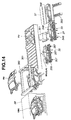
- the RDAPU 77 includes a sash module front pallet 79, a door mirror unit pallet 83, an interior trim module pallet 85, and an inner module pallet 87 around a roller conveyer 467 to make it easier for workers to assemble parts.
- the LDAPU 78 is substantially the same in construction as the RDAPU 77 so that the same reference numerals are used to designate like portions. Lifts 4 are provided adjacent the RDAPU 77 and LDAPU 78, respectively.
- a die casting process is used to make a light metal die cast part, which serves as one of floor constituent parts.
- molten light metal such as aluminum (Al) alloy and magnesium (Mg) alloy
- the floor constituent parts are made of aluminum alloy extrusion die cast products.
- the FPU A workers manually engage in assembling the floor constituent parts.
- a welding machine welds the assembled floor constituent parts to produce a floor structure.
- the IPMPU B the rear floor module, rear end module, dash module, engine room parts, carpet, rear sheet, console, and front sheet are mounted onto the floor structure to produce a floor unit (FU).
- the floor unit is conveyed to the BMPU C.
- a roof decoration plate of synthetic resin, a rear fender decoration plate of synthetic resin, a front fender decoration plate of synthetic resin, a trunk lid decoration plate of synthetic resin, and a hood decoration plate of synthetic resin are attached to the vehicle core.
- An inspection line follows the EPDPU E.
- a painting process is no longer required. Thus, there is no need to alter painting equipment to cope with color switching. Assembling bodies can synchronize with assembling of vehicles. Stocks of bodies and parts associated therewith are greatly reduced, in number.
- Figure 2H illustrates a vehicle off the assembly line immediately downstream of the ESDPU E, which vehicle has attached thereto a roof panel of synthetic resin 143, a rear fender panel of synthetic resin 145, a front fender panel of synthetic resin 147, a trunk lid panel of synthetic resin 149, and a hood panel of synthetic resin 151.
- the sub-process unit 7 provides for manual assembly, on the roller conveyer 155, of parts needed to make the engine compartment frame 187.
- the sub-process unit 9 provides for manual assembly, on the roller conveyer 157, of parts needed to make the rear floor frame 189.
- the floor main process unit 5 provides for manual assembly, on the roller conveyer 153, of the front floor constituent parts 191, 193, and 195, the engine compartment frame 187 and rear floor frame 189.
- Figure 4A illustrates the front, intermediate, and rear constituent parts 192, 193, and 195 of the front floor.
- Each of them is an aluminum alloy extrusion die cast product that has been made, in an extrusion die casting process, by forcing molten aluminum alloy through the mold cavity in a direction adapted to be parallel to a transverse direction of the vehicle.
- the front, intermediate, and rear constituent parts 192, 193, and 195 are formed with locate holes 197, 199, and 201, respectively.
- the front and intermediate constituent part 191 and 193 are formed with grooves 205 and 207 adapted to receive seat attachment brackets 203.
- the locate holes 197, 199, and 201 as well as the grooves 205 and 207 are formed in the die casting process.
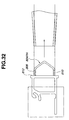
- the female coupling section 211 has a groove that is defined by the bottom wall 221 and two spaced parallel flange inner walls 235 extending from the bottom wall 221.
- the inboard or upper flange extends further than the outboard or lower flange does to prevent transmission of noises to the vehicle cabin.
- Clips 227 are disposed near leading ends of the inner walls of the upper and lower flanges to define a mouth of the groove.
- the clips 227 protrude inwardly from the upper and lower flanges, respectively.
- the male coupling section 213 is formed with clip receiving recesses 229, which receive the clips 227, respectively.
- a bolt 258 is engaged into one of the through holes 253 and the through hole of the left-hand side member .
- Another bolt 258 is engaged into the other through hole 253 and the through hole of the right-hand side member.
- the front side members 241 are provisionally connected to the dash lower cross member 237.
- the assembled engine compartment frame 187 is joined with the front floor constituent part 191 by engaging the male coupling section 209 in the female coupling section 243.
- the female coupling section 243 is provided with two clips 227 and a positioning protrusion 223.
- the female coupling section 243 and the male coupling section 209 are substantially the same in structure with the female and male coupling sections 211 and 213 illustrated in Figures 5A to 5C.
- FIGS 7A and 7B illustrate a rear floor frame 189, which serves as a constituent part of the floor.
- the rear floor frame 189 is made of and dividable into six parts, namely, a pair of rear side members (front) 261, a pair of rear side members (rear) 263, a rear cross member (front) 265, and a rear cross member (rear).
- the rear side members (front) 261 on the left-hand side and right-hand side are of symmetry in structure. They are given after cutting an aluminum alloy extrusion die cast product that is prepared by a die casting process in which molten aluminum alloy is forced through a mold in a direction along the longitudinal direction of the vehicle, viewing in Figure 7A.
- the rear cross member (front) 265 and rear cross member (rear) 267 are given after cutting an aluminum alloy die case product that is prepared by a die casting process in which molten aluminum alloy is forced through a mold in a direction along the vertical direction of the vehicle.
- Provisional connection between the rear cross member (front) 265, rear cross member (rear) 267, and left-hand and right-hand rear side members (front) 261 is made by locate pins, not shown, inserted through the locate holes 269.
- the rear cross member (front) 265 is also formed with a locate hole 271. Inserting the locate pins into the locate holes 269 and 271 results in the provisional connection of the rear cross member (front) 265 with the rear side members (front) 261.
- the provisional connection of the rear cross member (rear) 267 with the rear side members (front) 261 is made by the locate pins.
- each of the floor structure constituent parts which are made of dies casting products, fall within ranges easy to manipulate with.
- the maximum length is 1400 mm and the maximum weight is 10 kg.
- each of the coupling portions does not require a force greater than a manual force by workers during work to complete coupling between the adjacent two constituent parts due to snap action type clips.
- Figures 8A, 8B, and 8C are exploded views of three floor structures resulting from modifications made to cope with three different vehicle types.
- Figure 8A illustrates constituent parts of a standard floor structure.
- Figure 8B illustrates constituent parts of a floor structure to cope with a wide body type.
- Figure 8C illustrates constituent parts of a floor structure to cope with a long wheel base type.
- the floor structure 113 resulting from provisional interconnection of the constituent parts is transferred by a manual roller conveyer 279 to the WPU 3.
- the WPU 3 is installed within a site that is kept off by two spaced partitions only one being indicated at 281.
- a motor driven shutter 283 is provided to close an entry to the site and another motor driven shutter 284 is provided to close an exit from the site.
- the motor driven automatic conveyer 285 is equipped with two parallel belts 295 and 297.
- the belts 295 and 297 extend over a base 293.
- the base 293 has therein a drive mechanism including a motor.
- the motor drives a drive roller 299.
- the belts 295 and 297 extend between the drive roller 299 and an idle roller 301.
- the laser weld robot 287 is located on one side of the conveyer 285.
- the work detector 291 is mounted to the conveyer 285 between the belts 295 and 297.
- the work detector 291 has a stop that can pivot upwards into abutting engagement with the engine compartment frame of the floor structure 113 on the conveyer 285 for detecting the floor structure 113 as well as positioning with regard to the work transfer direction.
- the work detector 291 Upon completion of weld operation by the laser weld robot 287, the work detector 291 causes its stop to pivot back to assume a horizontal rest position.
- the floor structure 113 is transferred manually along the roller conveyer 279 from the FMPU 5 to a position in front of the entrance of the WPU 3 where the motor driven shutter 283 is open.
- the belts 295 and 297 of the conveyer 285 start to move. What workers have to do is to push the floor structure 113 onto the belts 295 and 297. Then, the conveyer 285 pulls the floor structure 113 into the site where the robot 287 is.
- the REMPU 13 includes a roller conveyer 333.
- the roller conveyer 333 includes two spaced belts 333a and 333b, which are arranged on different levels to support a rear end panel 335. Near one end of the roller conveyer 333, a pallet 337 is arranged. The pallet 337 stores rear end panels 335.
- the front seats 119 and 121 are attached to the brackets 203 engaged in the grooves 205 and 207 of the front floor constituent parts 191 and 193.
- the brackets 203 have been inserted from open ends of the grooves 205 and 207 inwardly to predetermined positions. Using a proper jig, not illustrated, the brackets 203 are appropriately positioned.
- the rear seat is attached to the floor structure 113 in the similar manner. In this manner, a floor unit FU is made.
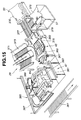
- Pallets are arranged around the SPU 45 and store different interior parts for different vehicle body types, respectively.
- Figure 15 illustrates a pallet 53 storing an interior part for wagon 376 and a pallet 57 storing an interior part for M sedan 378.
- a roller conveyer 377 is associated with the pallet 53 to facilitate manual transfer of the part to the SPU 45.
- a roller conveyer 379 is associated with the pallet 57 to facilitate manual transfer of the part to the SPU 45.
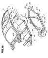
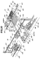
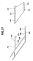
- Figure 16 illustrates where a floor unit FU, a body side unit BSU, and a roof unit RU are positioned relative to each other as well as structures for positioning.
- the lower structure is arranged in a level lower than a lower end of the center pillar 397.
- the locate pins 391 and 393 and the locate holes 197 and 199 have their axes, respectively, and they are arranged with their axes lying in a traverse direction with respect to a longitudinal direction of the vehicle body.
- the locate pin 413 of the roof unit RU is disposed at where the front pillar 407 and a hood ridge 408 are joined.
- the locate pin 415 is disposed where the center pillar 409 and a roof side rail 410 are joined.
- the locate pin 417 is disposed where the rear pillar 411, a rear roof rail 412, and a roof side rail 410 are joined.
- Figure 18A illustrates the position of the body side units BSU before engagement with the roof unit RU
- Figure 18B illustrates the position of the body side units BSU after engagement with the roof unit.
- Each of the pins 393 of the lower positioning structure is inserted into the locate hole 199 in horizontal direction
- each of the pins 415 of the upper positioning structure is inserted into the locate hole 403 in vertical direction. This connecting structure reduces the angle ⁇ further toward zero.
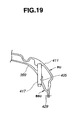
- Figure 19 illustrates structure around the pin 417 of the rear pillar 411 of the roof unit RU inserted into the locate hole 405 through the rear pillar 399 of the body side unit BSU. As shown in Figure 19, the rear pillar 411 of the roof unit RU is welded, by laser welding, to the rear pillar 399 of the body side unit BSU at 429.
- the flanges 430A and 430C are welded, by laser welding, to the body side unit BSU and the roof unit RU, respectively, to provide the closed sectioned structure reinforcing the roof side rail 410 (see Figure 16).
- the preceding description now clearly indicates that laser welding between the flange 430A of the roof unit RU and each of the body side unit BSU and between the flange 430B of each of the body side unit BSU and the roof unit RU completes a closed cross section structure. This structure reinforces the connection between the roof unit RU and each of the body side units BSU.
- the inner trimming is temporarily removed to expose a clearance between each of the protrusions 421 of the body side units BSU and the inner plate 419 (see Figure 17) of the floor unit FU. Subsequently, the adhesive is put into the exposed clearances.
- the inner trimming is temporarily removed to expose overlapped portions between the flanges 430C of the body side units BSU and the portions 430D (see Figure 18A). Subsequently, these overlapped portions are welded by laser welding. In this manner, good appearance of the interior of the vehicle cabin is maintained. Finally, these temporarily removed trimming parts are mounted again. Such parts to be temporarily removed should be as small as possible to cover only the adhesive and welding connections to avoid any delay work in connecting the vehicle body parts to each other.
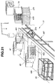
- the body unit UBU that has been welded by laser welding operation at the WPU 58 is transferred to the RPMPU D where the body unit UBU and the under running unit URU 60 are joined.
- the RPMPU D includes two automatic conveyers 431 and 433.
- the automatic conveyer 431 extends on downstream side of the WPU 58 (see Figure 14).
- This automatic conveyer 431 is substantially the same as the automatic conveyer 285 illustrated in Figure 9 and includes a pair of parallel belts 435, which are driven by a motor under a controller.
- a power-assisted lift 437 is arranged near the downstream end of the automatic conveyer 413.
- This lift 437 includes a platform supported by extendable cylinders 439. Activating the cylinders 439 lifts the platform of the lift 437.
- the other automatic conveyer 433 is arranged downstream of the automatic conveyer 431. Similarly, the automatic conveyer 433 includes a pair of parallel belts 441, which are driven by a motor under a controller.
- the rail 443 and the wheeled shifter 447 are lowered again and the wheeled shifter 447 releases the main body MB.
- the rail 443 and the wheeled shifter 447 are elevated again leaving the main body MB on the automatic conveyer 433.
- the wheeled shifter 447 moves back to the first position again.
- Each of the automatic conveyers 449 and 451 is equipped with a pair of belts 457.
- the automatic conveyer 449 transfers the pallet 459 having an under running unit URU 60, while the automatic conveyer 451 transfers the empty pallet 461.
- Each of the pallets 459 and 461 is provided with set pins 463.
- Each pallet 459 or 461 is equipped with a set of four guide rollers 464 at corners thereof, respectively. The guide rollers of each pallet can rotate about vertical axes, respectively.
- the workers move the pallet 459 along the guide rail 456 to a predetermined position between the automatic conveyers 431 and 433. Movement of the pallet 459 beyond this predetermined position is limited by the stop 468.
- the guide rollers 464 are in rolling contact with the channel shaped rails 465 for smooth movement of the pallet 459.
- the lift 445 elevates the rail 443 again to the elevated position. Then, the wheeled shifter 447 with the main body MB moves in the downstream direction toward the third position above the automatic conveyer 433. After reaching the third position above the automatic conveyer 433, the rail 443 is lowered by the lift 445 and the wheeled shifter 447 releases the main body MB to set it on the automatic conveyer 433. The lift 445 elevates the rail 443 again to the elevated position.
- the empty wheeled shifter 447 moves in an upstream direction toward the first position above the platform of the lift 437 of the automatic conveyer 431.
- the automatic conveyer 433 transfers the main body MB to the next EPAPU F where exterior parts are attached to the main body MB.
- the empty pallet is moved back along the guide rail 456 to the roller conveyer 455.
- the empty pallet is moved back via the ball roller table 453 to the automatic conveyer 451.
- the worker supplies the main body MB with long life coolant from the long life coolant supply station 68, gasoline from the gasoline supply station 69, brake oil from the brake oil supply station 71, and power steering oil from the power steering oil supply station 73.
- workers transfer the main body MB toward the WAPU H using the roller conveyer.
- the resin panels are classified in accordance with a production schedule and then supplied to the pallets 89, 92, 93, 95 and 97.
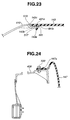
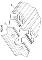
- Figures 23, 24 and 25 illustrate structures via which the resin panels are attached to the main body MB.
- a lower edge portion of the rear fender resin panel 145 is fixedly connected to a wheelhouse opening defining edge 521 of the body side unit BSU by means of resin clips, only being shown at 523.
- the front fender resin panel 145 has a curved portion 145a.
- the preferred implementation of the present invention can considerably reduce money reserved for repairing any damage on body panels, which might occur during the production line. This is because resin panels are attached to the vehicle body at the final stage of the vehicle production line.
- the preferred implementation of the present invention has abolished the conventional painting and coating process of vehicle body and provided a superior vehicle body structure owing to the use of corrosion resisting light metal alloy, such as aluminum alloy.
- the preferred implementation of the present invention has improved working environment by eliminating jobs within a closed space defined by a vehicle body.
- a worker In the conventional vehicle production line, a worker has to enter a narrow closed space defined by a vehicle body to set seats, an instrument panel and harness.
- the closed space demands that worker continues jobs in an uncomfortable posture in bad working environment where he/she is not allowed to take a standing position.
- the preferred implementation provides good working environment by allowing a worker or workers to conduct jobs in an open space on a floor unit. Subsequently, the floor unit, body side units and a roof unit are joined to form a vehicle body.
- Each of the body side units includes a door trimming, and the roof unit includes a roof lining. Providing such good environment may result in increased working efficiency.
- the preferred implementation according to the present invention greatly reduces the total stock of vehicles waiting for shipment by employing production on orders, bringing about a reduction in cost for transportation and stock control.
- the very compact production line enormously shorten period of time from order to delivery, making it possible to change the current anticipated production to production on orders.
- the preferred implementation according to the present invention has made it possible to abolish a jig for holding vehicle body parts during process of connecting them together.
- Pin and locate hole connection which is employed in assembling a floor unit, body side units and a roof unit, functions to perform positioning as well as interconnection, thus eliminating a need of a jig.
- the preferred implementation according to the present invention has lowered the amount of money to be spent for a variety of three-dimensional body appearances, which are to be prepared to meet varying design demands by users.
- Resin panels with different colors and three-dimensional appearances are prepared as body panels and selectively for attachment, by means of bolts and/or clips, to cope with such varying design demands. Preparation for such resin panels can be made without any modification of the production line.
- the preferred implementation according to the present invention has lowered the amount of money reserved for repairing any damage on body surface as a result of a remarkable drop in probability of occurrence of damage.
- the attachment of resin panels is conducted at the final stage of the production line, causing such remarkable drop in occurrence of damage within a vehicle production plant.
- the preferred implementation according to the present invention has extended period of time for which a body structure may be used by using the body structural parts of anticorrosion material such as aluminum alloy.
- anticorrosion material such as aluminum alloy.
- Such anticorrosion material possesses superior in rust resisting at edges of openings of the body structure.
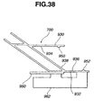
- FIG. 26 to 33 another example of a front floor 600 is explained as well as a dash cross member 700 and joints 800RH and 800LH.
- Each of the constituent parts is an aluminum alloy extrusion die cast product that has been made, in an extrusion die casting process, by forcing molten aluminum alloy through a mold cavity in a direction parallel to a longitudinal direction of the vehicle.
- Each of the joints 800RH and 800LH is an aluminum alloy extrusion die cast product that has been made, in an extrusion die casting process, by forcing molten aluminum alloy through a mold cavity in a direction parallel to a transverse direction of the vehicle.
- the dash cross member 700 is an aluminum alloy extrusion die cast product that has been made, in an extrusion die casting process, by forcing molten aluminum alloy through a mold cavity in a direction parallel to the transverse direction of the vehicle. Via the joints 800RK and 800LH, the front floor 600 is connected to the dash cross member 700.
- wedges 802LH, 804LH, 806LH, 802RH, 804RH, and 806RH are operative, when the front floor parts are welded as shown in Figure 29, to reduce a clearance between the left-hand floor center 604LH and the left-hand side sill, a clearance between the left-hand floor center 604LH and the tunnel 602, a clearance between the right-hand floor center 604RH and the right-hand side sill 606RH, and a clearance between the right-hand floor center 604RH and the tunnel 602.
- These wedges are operative also to suppress variations between the clearances. Besides, these wedges are operative to reduce distortion owing to stress during welding operation. Accordingly, there are realized welding connections of sufficiently high level of strength, providing quality stability and reliability of the products.
- the right-side sill 606 and the right-hand front floor center 604RH are coupled with each other after moving the side sill 606RH along a horizontal plane toward and into engagement fit with the front floor center 604RH (see Figure 28).
- the tunnel 602 and the right-hand front center 604RH are coupled with each other after moving the tunnel 602 along horizontal plane toward and into engagement fit with the front floor center 604RH.
- the left-hand front floor center 604LH are coupled with the tunnel 602 after moving the front floor center 604LH along horizontal plane toward and into engagement fit with the tunnel 602.
- the left-hand side sill and the front floor center 604LH are coupled with each other after moving the left-hand side sill along horizontal plane toward and into engagement fit with the front floor center 604LH.
- the right-hand front center 604RH is connected to the tunnel 602 by welding at portions 818.
- the left-hand front center 604LH is connected to the tunnel 602 by welding at portions 820.
- This engine compartment frame includes a bumper stay 900, two side member assemblies 902 extending from the dash cross member 700 to the bumper stay to hold the bumper stay 900.
- Each of the side member assemblies 902 has a front member 904, a rear member 906, and a joint 908 interconnecting the front and rear members 904 and 906.
- a reinforcement member 910 supports the rear ends of the rear members 906.
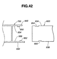
- the upper and lower protrusions 950 and 952 engage in the upper and lower recesses 954 and 956, respectively, when the male coupling section is inserted into the groove of the female coupling section. Engagement of the protrusions 950 and 952 with the recesses 954 and 956 will automatically position the front floor structure 600 relative to the dash cross member 700 in the longitudinal line of the vehicle. This feature has made it easier to assemble the front floor structure 600 and the dash cross member 700 with sufficiently good accuracy. No equipment to position the front floor structure relative to the dash cross member 700 is needed in assembly. This temporal connection can suppress any deviation that might be caused by vibrations during conveyance.
- the lower protrusion 952 is not located below the upper protrusion 950.
- the lower protrusion 952 is remoter from a frontal end of the vehicle, not shown, toward the vehicle rear end than the upper protrusion 950 is.
- the upper and lower flanges 930 and 932 overlap the upper and lower outer walls 940 and 942, respectively.
- This connecting structure is effective in suppressing the amount of deformation of the dash cross member 700 when it is subjected to a counterclockwise bending moment viewing in Figure 37 because of distribution of stress. Such bending moment is imparted to the dash cross member 700 during the vehicle frontal collision.
- the illustrated embodiment employs assembling the body side units with the floor unit, and subsequent assembling a roof unit to the assembled body side units and floor unit for accurately locating the roof unit in required accurate geometric relation.
- it may employ assembling body side units with a roof unit, and subsequent assembling the assembled roof unit and body side units for accurately locating the roof unit in required accurate geometric relation.
Landscapes
- Engineering & Computer Science (AREA)
- Mechanical Engineering (AREA)
- Chemical & Material Sciences (AREA)
- Combustion & Propulsion (AREA)
- Transportation (AREA)
- Physics & Mathematics (AREA)
- Optics & Photonics (AREA)
- Manufacturing & Machinery (AREA)
- Plasma & Fusion (AREA)
- Architecture (AREA)
- Structural Engineering (AREA)
- Robotics (AREA)
- Body Structure For Vehicles (AREA)
- Automobile Manufacture Line, Endless Track Vehicle, Trailer (AREA)
Priority Applications (1)
| Application Number | Priority Date | Filing Date | Title |
|---|---|---|---|
| EP05005401A EP1541455B1 (fr) | 1998-12-11 | 1999-12-09 | Production de véhicules |
Applications Claiming Priority (2)
| Application Number | Priority Date | Filing Date | Title |
|---|---|---|---|
| JP35342898 | 1998-12-11 | ||
| JP35342898 | 1998-12-11 |
Related Child Applications (2)
| Application Number | Title | Priority Date | Filing Date |
|---|---|---|---|
| EP05005401A Division EP1541455B1 (fr) | 1998-12-11 | 1999-12-09 | Production de véhicules |
| EP05005401.4 Division-Into | 2005-03-11 |
Publications (3)
| Publication Number | Publication Date |
|---|---|
| EP1008510A2 true EP1008510A2 (fr) | 2000-06-14 |
| EP1008510A3 EP1008510A3 (fr) | 2003-11-05 |
| EP1008510B1 EP1008510B1 (fr) | 2013-03-06 |
Family
ID=18430782
Family Applications (2)
| Application Number | Title | Priority Date | Filing Date |
|---|---|---|---|
| EP05005401A Expired - Lifetime EP1541455B1 (fr) | 1998-12-11 | 1999-12-09 | Production de véhicules |
| EP99124559A Expired - Lifetime EP1008510B1 (fr) | 1998-12-11 | 1999-12-09 | Production de véhicules |
Family Applications Before (1)
| Application Number | Title | Priority Date | Filing Date |
|---|---|---|---|
| EP05005401A Expired - Lifetime EP1541455B1 (fr) | 1998-12-11 | 1999-12-09 | Production de véhicules |
Country Status (3)
| Country | Link |
|---|---|
| US (3) | US6334252B1 (fr) |
| EP (2) | EP1541455B1 (fr) |
| DE (1) | DE69943250D1 (fr) |
Cited By (8)
| Publication number | Priority date | Publication date | Assignee | Title |
|---|---|---|---|---|
| FR2849423A1 (fr) * | 2002-12-26 | 2004-07-02 | Renault Sa | Assemblage d'un element de carrosserie d'automobile, notamment de cadre de portiere |
| EP1747975A1 (fr) * | 2005-07-27 | 2007-01-31 | Plastal GmbH | Module de toit pour des véhicules automobiles |
| WO2008128607A1 (fr) * | 2007-04-23 | 2008-10-30 | Khs Ag | Procédé de production pour machines |
| WO2009030310A1 (fr) * | 2007-08-30 | 2009-03-12 | Khs Ag | Procédé de fabrication de machines |
| WO2015007387A3 (fr) * | 2013-07-16 | 2015-04-23 | Quali Gmbh | Procédé de fabrication d'un élément structural |
| CN109676279A (zh) * | 2019-02-02 | 2019-04-26 | 宁波吉利汽车研究开发有限公司 | 一种多车型柔性制造方法及装置 |
| CN111372837A (zh) * | 2017-11-22 | 2020-07-03 | 皮耶希设计公司 | 汽车的车身平台以及包括这种车身平台的汽车 |
| WO2024104959A1 (fr) * | 2022-11-14 | 2024-05-23 | Bayerische Motoren Werke Aktiengesellschaft | Procédé pour la production d'un véhicule à moteur, et véhicule à moteur |
Families Citing this family (94)
| Publication number | Priority date | Publication date | Assignee | Title |
|---|---|---|---|---|
| US6877786B2 (en) * | 2000-01-21 | 2005-04-12 | Visteon Global Technologies, Inc. | Thermally energy efficient vehicle |
| JP2001301653A (ja) * | 2000-04-25 | 2001-10-31 | Nissan Motor Co Ltd | 自動車の車体組立方法および車体構造 |
| US6493920B1 (en) * | 2000-09-07 | 2002-12-17 | Ford Global Technologies, Inc. | Method of assembling a vehicle from preassembled modular components |
| US7734781B2 (en) * | 2001-07-09 | 2010-06-08 | Savvis Communications Corporation | Methods and systems for shared storage virtualization |
| US6843336B2 (en) * | 2001-08-23 | 2005-01-18 | General Motors Corporation | Vehicle belly pan |
| US7165929B2 (en) * | 2001-12-20 | 2007-01-23 | Caterpillar Inc | Load bearing member arrangement and method |
| US20030159264A1 (en) * | 2002-02-22 | 2003-08-28 | The Dow Chemical Company | Automotive roof module and method of assembly of the module to an automotive vehicle |
| US6918169B2 (en) | 2002-05-14 | 2005-07-19 | Mathson Industries | Method of assembling a vehicle |
| DE10221733B4 (de) * | 2002-05-16 | 2010-08-12 | Dr. Ing. H.C. F. Porsche Aktiengesellschaft | Be- und Entladestation für Ladungsträger von Fahrzeugkarossen, Fahrzeugen und dergleichen |
| DE10233280B4 (de) * | 2002-07-23 | 2005-09-01 | Arvinmeritor Gmbh | Fahrzeugdachmodul |
| DE10239988A1 (de) * | 2002-08-27 | 2004-04-15 | Daimlerchrysler Ag | Karosserie für einen Kraftwagen |
| US20040055147A1 (en) * | 2002-09-24 | 2004-03-25 | Abid Ghuman | Process line for a flexible manufacturing system |
| US7178227B2 (en) * | 2002-09-24 | 2007-02-20 | Ford Motor Company | Workpiece presenter for a flexible manufacturing system |
| US20040055129A1 (en) * | 2002-09-24 | 2004-03-25 | Abid Ghuman | Method of engineering a flexible process line |
| US6899377B2 (en) * | 2002-09-24 | 2005-05-31 | Ford Motor Company | Vehicle body |
| US20040056069A1 (en) * | 2002-09-24 | 2004-03-25 | Abid Ghuman | Method of engineering a process line for a flexible manufacturing system |
| US20040056497A1 (en) * | 2002-09-24 | 2004-03-25 | Abid Ghuman | Flexible manufacturing system |
| US6918577B2 (en) * | 2002-09-24 | 2005-07-19 | Ford Motor Company | Tooling plate for a flexible manufacturing system |
| US20040055131A1 (en) * | 2002-09-24 | 2004-03-25 | Abid Ghuman | Method of assembling vehicles in a flexible manufacturing system |
| GB2401085B (en) * | 2003-04-29 | 2005-08-17 | Gibbs Tech Ltd | Vehicle body construction |
| US20050116460A1 (en) * | 2003-10-17 | 2005-06-02 | Mcgill Scott M. | Method of manufacturing a frame assembly |
| US6976309B2 (en) * | 2003-12-18 | 2005-12-20 | General Motors Corporation | Vehicle underbody and method of forming thereof |
| US20050223532A1 (en) * | 2004-04-08 | 2005-10-13 | Ford Global Technologies, Llc | Method of designing a vehicle closure assembly line |
| JP2006043866A (ja) * | 2004-06-30 | 2006-02-16 | Fanuc Ltd | パレット交換機能を有する工作機械及びパレット交換方法 |
| DE102005036243A1 (de) * | 2005-08-02 | 2007-02-08 | Wilhelm Karmann Gmbh | Herstellung von Cabriolet-Dächern |
| US7520560B2 (en) * | 2005-08-12 | 2009-04-21 | Ford Global Technologies, Llc | Method of bonding and sealing automotive structural component joints |
| DE102005050249A1 (de) * | 2005-10-20 | 2007-04-26 | Volkswagen Ag | Flexibles fügeoptimiertes Anbauteil |
| KR100667380B1 (ko) * | 2005-11-02 | 2007-01-10 | 현대자동차주식회사 | 엔진의 유동통로 마감 장치 |
| US7293823B2 (en) * | 2005-11-16 | 2007-11-13 | Ford Global Technologies, Llc | Interlocked pillar and roof rail joint |
| US7695056B2 (en) * | 2006-05-05 | 2010-04-13 | Textron Innovations Inc. | Floorboard for light-weight vehicle |
| US7703841B2 (en) * | 2007-01-11 | 2010-04-27 | Ford Motor Company | Vehicle body assembly |
| US7677649B2 (en) * | 2007-01-11 | 2010-03-16 | Ford Motor Company | Vehicle having an interlocking floor assembly |
| US7717465B2 (en) * | 2007-01-11 | 2010-05-18 | Ford Motor Company | Vehicle having an engine support structure |
| US7798560B2 (en) * | 2007-01-11 | 2010-09-21 | Ford Motor Company | Vehicle body structure |
| US8317964B2 (en) * | 2007-01-11 | 2012-11-27 | Ford Motor Company | Method of manufacturing a vehicle |
| US7618087B2 (en) * | 2007-01-11 | 2009-11-17 | Ford Motor Company | Vehicle having a front end body structure |
| US7591502B2 (en) * | 2007-01-11 | 2009-09-22 | Ford Motor Company | Tunable inner fender structure |
| US7850226B2 (en) * | 2007-01-11 | 2010-12-14 | Ford Motor Company | Vehicle having a passenger compartment body structure |
| US8038205B2 (en) * | 2007-01-11 | 2011-10-18 | Ford Motor Company | Vehicle having a passenger compartment body structure |
| US8123284B2 (en) * | 2007-01-11 | 2012-02-28 | Ford Motor Company | Vehicle body component and mating feature |
| US7849601B2 (en) * | 2007-01-11 | 2010-12-14 | Ford Motor Company | Method of manufacturing a vehicle |
| US7810876B2 (en) * | 2007-01-11 | 2010-10-12 | Ford Motor Company | Vehicle having a rear end body structure |
| US8177277B2 (en) * | 2007-01-11 | 2012-05-15 | Ford Motor Company | Vehicle having a body panel |
| DE102007049752A1 (de) | 2007-03-21 | 2008-09-25 | Johnson Controls Gmbh | Montageverfahren zur Bildung einer Sitzstruktur eines Fahrzeugsitzes und Sitzstruktur |
| WO2008157281A2 (fr) * | 2007-06-13 | 2008-12-24 | Alcoa Inc. | Article métallique recouvert, et procédé de fabrication de celui-ci |
| US8046895B2 (en) * | 2008-01-21 | 2011-11-01 | Ford Motor Company | System and method for assembling a vehicle body structure |
| DE102008036893B4 (de) * | 2008-08-07 | 2020-08-06 | Bayerische Motoren Werke Aktiengesellschaft | Verfahren zum Herstellen einer Karosserie eines Kraftfahrzeugs |
| DE102009017380A1 (de) * | 2009-04-14 | 2010-10-21 | GM Global Technology Operations, Inc., Detroit | Modulare Fahrzeugsitzrahmenkomponente |
| DE102009019741A1 (de) * | 2009-05-02 | 2010-11-11 | Thyssenkrupp Drauz Nothelfer Gmbh | Anlage zur Montage von Karosserieteilen |
| US8201596B2 (en) * | 2009-09-22 | 2012-06-19 | GM Global Technology Operations LLC | Method of filling a fuel tank |
| US20110097598A1 (en) * | 2009-10-28 | 2011-04-28 | Mcnutt Matthew M | Laser-welded aluminum alloy parts and method for manufacturing the same |
| DE102010005314A1 (de) * | 2010-01-21 | 2010-08-19 | Daimler Ag | Montageeinrichtung |
| DE102010030515A1 (de) * | 2010-06-25 | 2011-12-29 | Bayerische Motoren Werke Aktiengesellschaft | Karosserie für ein Kraftfahrzeug |
| EP2431248B1 (fr) * | 2010-09-16 | 2012-12-19 | Wilhelm Wißmann GmbH | Sol pour un véhicule sur rail |
| EP2441653B1 (fr) * | 2010-10-13 | 2016-04-06 | Daimler AG | Dessous de caisse pour une multitude de versions de construction d'une carrosserie d'un véhicule de tourisme, notamment dotée d'un agrégat d'entraînement de capot |
| US20120104793A1 (en) * | 2010-10-29 | 2012-05-03 | Aptera Motors, Inc. | Automotive vehicle composite body structure |
| US9540185B2 (en) | 2011-06-24 | 2017-01-10 | Toyota Motor Engineering & Manufacturing North America, Inc. | Rack stopper system |
| AU2012279691B2 (en) * | 2011-07-04 | 2016-03-31 | Honda Motor Co., Ltd. | Vehicle body structure and method for assembling vehicle body structure |
| CN103619695B (zh) * | 2011-10-11 | 2015-12-02 | 铃木株式会社 | 车辆前部的下部车体结构 |
| US9132872B2 (en) * | 2013-03-14 | 2015-09-15 | Honda Motor Co., Ltd. | System for assembling a vehicle body |
| CN103286467B (zh) * | 2013-06-24 | 2016-08-24 | 合肥长安汽车有限公司 | 一种控制车架总成变形的焊接方法 |
| US9290206B2 (en) * | 2013-06-28 | 2016-03-22 | GM Global Technology Operations LLC | Cast datums for wheelbase tuning |
| KR101490923B1 (ko) * | 2013-08-09 | 2015-02-06 | 현대자동차 주식회사 | 리어 사이드 멤버를 구비한 차체 |
| JP2016055778A (ja) * | 2014-09-10 | 2016-04-21 | トヨタ自動車株式会社 | 車両前部構造 |
| DE102014018994A1 (de) * | 2014-12-18 | 2016-06-23 | GM Global Technology Operations LLC (n. d. Gesetzen des Staates Delaware) | Fahrzeugkarosserie mit geklebtem Fahrzeugdach sowie Verfahren zur Herstellung eines Kraftfahrzeuges |
| US9505439B2 (en) * | 2015-04-15 | 2016-11-29 | Ford Global Technologies, Llc | Variable width platform vehicle body structure and method |
| CN105965210B (zh) * | 2016-06-23 | 2017-11-17 | 东莞理工学院 | 一种示教性机械手制造与组装一体化的成型工艺 |
| US10266210B2 (en) | 2016-09-07 | 2019-04-23 | Thunder Power New Energy Vehicle Development Company Limited | Profile of the front cross member |
| CN106493541A (zh) * | 2016-11-02 | 2017-03-15 | 丹阳正联知识产权运营管理有限公司 | 一种汽车车灯涂胶压合装置 |
| CN106513261A (zh) * | 2016-11-02 | 2017-03-22 | 丹阳正联知识产权运营管理有限公司 | 一种汽车车灯涂胶压合装置 |
| US10611559B2 (en) | 2016-12-15 | 2020-04-07 | Qingdao Cimc Reefer Trailer Co., Ltd. | Inner corner connector |
| KR101865735B1 (ko) * | 2016-12-16 | 2018-06-08 | 현대자동차 주식회사 | 부품의 로봇 이송시스템, 및 이송방법 |
| EP3363719B1 (fr) * | 2017-02-15 | 2019-12-11 | MAGNA STEYR Fahrzeugtechnik AG & Co KG | Procédé de fabrication d'un véhicule automobile |
| CN107127505B (zh) * | 2017-06-07 | 2023-07-04 | 力帆实业(集团)股份有限公司 | 车架下体组合焊接工装 |
| JP6938667B2 (ja) | 2017-11-20 | 2021-09-22 | ヤマハ発動機株式会社 | コミュニケーションシート式車両 |
| WO2019098383A1 (fr) | 2017-11-20 | 2019-05-23 | ヤマハ発動機株式会社 | Véhicule à conduite autonome de type à sièges en face-à-face |
| EP3715228B1 (fr) * | 2017-11-20 | 2022-03-30 | Yamaha Hatsudoki Kabushiki Kaisha | Véhicule équipé d'un siège avant tourné vers l'arrière |
| CN107932362A (zh) * | 2017-11-22 | 2018-04-20 | 兴化市豪铭艾德金属制品有限公司 | 一种应用于汽车组装的凸轮轴铝合金支架 |
| US10906592B2 (en) * | 2017-12-01 | 2021-02-02 | Mazda Motor Corporation | Vehicle body structure |
| JP6452878B1 (ja) * | 2018-04-24 | 2019-01-16 | 株式会社神戸製鋼所 | ドアビーム |
| US10960518B1 (en) * | 2019-09-20 | 2021-03-30 | Anthony M. Barraco | Inserts for shielding aluminum vehicles from clamps |
| KR102807543B1 (ko) * | 2019-12-17 | 2025-05-13 | 현대자동차주식회사 | 차체 조립 구조 |
| DE102020118934A1 (de) * | 2020-07-17 | 2022-01-20 | 3M Company and 3M Innovative Properties Company | Verfahren zum Herstellen einer Karosseriekomponente einer Fahrzeugkarosserie eines Fahrzeugs sowie Karosseriekomponente und Fahrzeugkarosserie |
| CN112091552B (zh) * | 2020-07-17 | 2023-03-17 | 广州广汽荻原模具冲压有限公司 | 铝合金板材组合加工方法 |
| EP3988430A1 (fr) * | 2020-10-20 | 2022-04-27 | GMP Investments Holdings Limited | Structure de support de construction automobile, procédé et panneau pour sa réalisation |
| KR102934933B1 (ko) * | 2020-12-16 | 2026-03-05 | 현대자동차 주식회사 | 차량용 언더 바디의 플로워 연결 구조 |
| CN112874633B (zh) * | 2021-03-19 | 2022-10-11 | 重庆长安汽车股份有限公司 | 一种后车架连接件及其安装结构 |
| CN114799625A (zh) * | 2022-04-13 | 2022-07-29 | 长江智能科技(广东)股份有限公司 | 带有胎膜库的汽车内外饰件焊接生产线 |
| CN114919666A (zh) * | 2022-06-06 | 2022-08-19 | 蔚来汽车科技(安徽)有限公司 | 车辆及其车身前机舱架构 |
| CN116765660B (zh) * | 2023-06-29 | 2025-12-09 | 广东鸿图科技股份有限公司 | 一种适用于大型压铸件的连接件焊接方法及装置 |
| CN117600681B (zh) * | 2024-01-24 | 2024-04-02 | 山西华暖科技发展有限公司 | 一种岩棉板加工机床 |
| US20250282428A1 (en) * | 2024-03-08 | 2025-09-11 | Ford Global Technologies, Llc | Method for producing a vehicle body |
| EP4707133A1 (fr) * | 2024-09-09 | 2026-03-11 | Iveco S.P.A. | Carrosserie, cabine, véhicule et procédé de fabrication associé |
| CN119794166B (zh) * | 2024-12-26 | 2025-12-02 | 重庆江东机械有限责任公司 | 一种管板金属材料复合成形自动化产线 |
Family Cites Families (36)
| Publication number | Priority date | Publication date | Assignee | Title |
|---|---|---|---|---|
| US4194043A (en) * | 1978-06-05 | 1980-03-18 | Chrysler Corporation | Welded aluminum die cast article |
| IT1210614B (it) * | 1981-10-06 | 1989-09-14 | Fiat Auto Spa | Procedimento per eseguire la lastra tura della scocca di un veicolo utilizzando elementi di rivestimento esterno costruiti in resine plastiche sintetiche |
| FR2574361B1 (fr) * | 1984-12-12 | 1987-01-23 | Cegedur | Platelage de vehicule |
| GB2168934B (en) * | 1984-12-19 | 1988-07-27 | Honda Motor Co Ltd | Method and apparatus for mounting parts to both sides of a main body |
| DE3603709A1 (de) * | 1986-02-06 | 1987-08-13 | Audi Ag | Verfahren zur montage von fahrzeugen, sowie vorrichtung zum durchfuehren des verfahrens |
| DE3720344A1 (de) * | 1987-06-19 | 1989-01-05 | Audi Ag | Verfahren zum herstellen einer rohkarosse sowie die rohkarosse selbst |
| JP2831999B2 (ja) * | 1987-12-01 | 1998-12-02 | マツダ株式会社 | 自動車組立ラインの足回り部組付装置 |
| JP2686977B2 (ja) | 1988-07-29 | 1997-12-08 | マツダ株式会社 | 自動車組立装置および自動車組立方法 |
| US5044541A (en) * | 1989-04-21 | 1991-09-03 | Nissan Motor Co., Ltd. | Method and apparatus for assembling vehicle body |
| JP2895906B2 (ja) * | 1990-03-31 | 1999-05-31 | マツダ株式会社 | 自動車車体の組立装置 |
| EP0477702B1 (fr) * | 1990-09-28 | 1994-03-09 | Mazda Motor Corporation | Procédé pour assembler une voiture |
| CA2054856C (fr) * | 1990-11-28 | 1994-12-13 | Akio Hamada | Systeme de montage de la carosserie de vehicules automobiles |
| JP2748691B2 (ja) | 1990-11-30 | 1998-05-13 | 日産自動車株式会社 | 自動車の製造方法 |
| KR970003573B1 (ko) * | 1990-12-28 | 1997-03-20 | 마쓰다 가부시끼가이샤 | 가공물 조립방법 및 그 장치 |
| JPH05105133A (ja) | 1991-03-20 | 1993-04-27 | Mazda Motor Corp | 自動車の製造方法 |
| JPH05105134A (ja) * | 1991-03-20 | 1993-04-27 | Mazda Motor Corp | 自動車の組立方法 |
| JPH05105136A (ja) * | 1991-05-10 | 1993-04-27 | Mazda Motor Corp | 自動車ボデイの搬送装置 |
| KR960007333B1 (ko) * | 1991-05-10 | 1996-05-31 | 마쓰다 가부시끼가이샤 | 자동차의 제조방법 |
| JP2957780B2 (ja) | 1991-05-10 | 1999-10-06 | マツダ株式会社 | 自動車の組立方法 |
| US5211216A (en) | 1991-09-23 | 1993-05-18 | Gibbs Die Casting Aluminum Corporation | Casting process |
| JP2966167B2 (ja) | 1991-12-06 | 1999-10-25 | マツダ株式会社 | 自動車の車体組立方法 |
| JPH05162670A (ja) * | 1991-12-17 | 1993-06-29 | Mazda Motor Corp | 自動車の車体構造及び車体組立方法 |
| US5209541A (en) | 1992-04-13 | 1993-05-11 | Ford Motor Company | Space frame joint construction |
| EP0568215A1 (fr) | 1992-04-29 | 1993-11-03 | Ford Motor Company Limited | Structure porteuse pour véhicules |
| US5267683A (en) * | 1992-12-01 | 1993-12-07 | Honda Giken Kogyo Kabushiki Kaisha | Apparatus for assembling motorcar vehicle body |
| JPH06171477A (ja) | 1992-12-04 | 1994-06-21 | Mazda Motor Corp | リサイクル自動車の製造システムとその製造方法及びリビルト自動車の製造システムとその製造方法 |
| DE4313562A1 (de) * | 1993-04-26 | 1994-10-27 | Opel Adam Ag | Karosserie für Kraftfahrzeuge |
| JP2793110B2 (ja) | 1993-09-09 | 1998-09-03 | 本田技研工業株式会社 | 自動車の製造ライン構成 |
| US5480208A (en) * | 1994-05-06 | 1996-01-02 | Aluminum Company Of America | S-portion for a frame-type vehicle body construction and an associated method |
| JPH08104264A (ja) | 1994-10-04 | 1996-04-23 | Sanyo Mach Works Ltd | 自動車ドアの製造ライン |
| JPH0999857A (ja) | 1995-10-04 | 1997-04-15 | Honda Motor Co Ltd | 自動車の車体構造 |
| JP3441576B2 (ja) | 1995-10-04 | 2003-09-02 | 本田技研工業株式会社 | 自動車のフロア構造 |
| JP4007519B2 (ja) | 1997-03-27 | 2007-11-14 | 本田技研工業株式会社 | 自動車製造方法 |
| DE19726723C1 (de) | 1997-06-24 | 1998-10-01 | Daimler Benz Ag | Verfahren zur Herstellung einer Rohbaukarosserie |
| JP4076664B2 (ja) * | 1999-03-19 | 2008-04-16 | 本田技研工業株式会社 | 車体構成部品の製造ライン |
| US6299240B1 (en) * | 2000-05-18 | 2001-10-09 | Daimlerchrysler Corporation | Lightweight vehicle frame construction using stiff torque boxes |
-
1999
- 1999-12-09 EP EP05005401A patent/EP1541455B1/fr not_active Expired - Lifetime
- 1999-12-09 DE DE69943250T patent/DE69943250D1/de not_active Expired - Lifetime
- 1999-12-09 EP EP99124559A patent/EP1008510B1/fr not_active Expired - Lifetime
- 1999-12-10 US US09/458,692 patent/US6334252B1/en not_active Expired - Lifetime
-
2001
- 2001-09-28 US US09/964,674 patent/US6668438B2/en not_active Expired - Lifetime
- 2001-09-28 US US09/964,675 patent/US6688674B2/en not_active Expired - Lifetime
Non-Patent Citations (1)
| Title |
|---|
| None |
Cited By (12)
| Publication number | Priority date | Publication date | Assignee | Title |
|---|---|---|---|---|
| FR2849423A1 (fr) * | 2002-12-26 | 2004-07-02 | Renault Sa | Assemblage d'un element de carrosserie d'automobile, notamment de cadre de portiere |
| EP1747975A1 (fr) * | 2005-07-27 | 2007-01-31 | Plastal GmbH | Module de toit pour des véhicules automobiles |
| WO2008128607A1 (fr) * | 2007-04-23 | 2008-10-30 | Khs Ag | Procédé de production pour machines |
| US8918980B2 (en) | 2007-04-23 | 2014-12-30 | Khs Gmbh | Beverage bottle handling machine construction method |
| WO2009030310A1 (fr) * | 2007-08-30 | 2009-03-12 | Khs Ag | Procédé de fabrication de machines |
| CN101657293B (zh) * | 2007-08-30 | 2014-03-19 | Khs有限责任公司 | 用于机器的制造方法 |
| US8978230B2 (en) | 2007-08-30 | 2015-03-17 | Khs Gmbh | Beverage bottle handling machine construction method |
| WO2015007387A3 (fr) * | 2013-07-16 | 2015-04-23 | Quali Gmbh | Procédé de fabrication d'un élément structural |
| CN111372837A (zh) * | 2017-11-22 | 2020-07-03 | 皮耶希设计公司 | 汽车的车身平台以及包括这种车身平台的汽车 |
| CN111372837B (zh) * | 2017-11-22 | 2022-11-08 | 皮耶希设计公司 | 汽车的车身平台以及包括这种车身平台的汽车 |
| CN109676279A (zh) * | 2019-02-02 | 2019-04-26 | 宁波吉利汽车研究开发有限公司 | 一种多车型柔性制造方法及装置 |
| WO2024104959A1 (fr) * | 2022-11-14 | 2024-05-23 | Bayerische Motoren Werke Aktiengesellschaft | Procédé pour la production d'un véhicule à moteur, et véhicule à moteur |
Also Published As
| Publication number | Publication date |
|---|---|
| US20020042996A1 (en) | 2002-04-18 |
| US6688674B2 (en) | 2004-02-10 |
| EP1008510A3 (fr) | 2003-11-05 |
| EP1008510B1 (fr) | 2013-03-06 |
| US6668438B2 (en) | 2003-12-30 |
| EP1541455A3 (fr) | 2006-05-17 |
| EP1541455B1 (fr) | 2011-03-02 |
| EP1541455A2 (fr) | 2005-06-15 |
| DE69943250D1 (de) | 2011-04-14 |
| US6334252B1 (en) | 2002-01-01 |
| US20020014008A1 (en) | 2002-02-07 |
Similar Documents
| Publication | Publication Date | Title |
|---|---|---|
| EP1008510B1 (fr) | Production de véhicules | |
| US7690552B2 (en) | Joining method and structure of metal members | |
| CN114430871A (zh) | 电动车辆用电池壳的制造方法及电动车辆用电池壳 | |
| US20100231007A1 (en) | Sunroof Reinforcement Assembly | |
| US20190291161A1 (en) | Progressive press line assembly | |
| JP2002542103A (ja) | 自動車両用の耐荷重構造 | |
| US11753079B2 (en) | Side sill for a motor vehicle | |
| US20030178883A1 (en) | Body support assembly for an off-highway truck | |
| JP3412587B2 (ja) | 自動車の製造方法、製造装置、及び自動車 | |
| JP3402239B2 (ja) | 自動車の製造方法及び自動車 | |
| EP3511085B1 (fr) | Structure porteuse d'une voiture de tourisme formée par pliage | |
| JPH05105135A (ja) | 自動車ボデイの搬送装置及び自動車の組立方法 | |
| JP2957780B2 (ja) | 自動車の組立方法 | |
| JP2907585B2 (ja) | 自動車の組立方法 | |
| JP2823890B2 (ja) | 自動車車体の組立ライン | |
| CN210172964U (zh) | 一种用于汽车下车身合拼台装置 | |
| Petring | Laser applications in European automotive manufacturing: Historical review and recent trends | |
| JP2907584B2 (ja) | 自動車の組立方法 | |
| JP2911642B2 (ja) | 自動車の製造方法 | |
| US20240124064A1 (en) | Unitary Truck Body and Associated Manufacturing Methods | |
| JPH0596238A (ja) | 自動車の製造方法 | |
| JPH05124547A (ja) | 自動車の製造方法 | |
| WO1999006267A1 (fr) | Ensemble de carrosserie de vehicule | |
| CN112739609A (zh) | 用于将安全带装置装入车辆车身中的方法 | |
| JP2001347967A (ja) | 車体構造 |
Legal Events
| Date | Code | Title | Description |
|---|---|---|---|
| PUAI | Public reference made under article 153(3) epc to a published international application that has entered the european phase |
Free format text: ORIGINAL CODE: 0009012 |
|
| 17P | Request for examination filed |
Effective date: 19991209 |
|
| AK | Designated contracting states |
Kind code of ref document: A2 Designated state(s): AT BE CH CY DE DK ES FI FR GB GR IE IT LI LU MC NL PT SE |
|
| AX | Request for extension of the european patent |
Free format text: AL;LT;LV;MK;RO;SI |
|
| RIN1 | Information on inventor provided before grant (corrected) |
Inventor name: KANAMORI, KENJI Inventor name: TAJIMA, TAKAMITSU Inventor name: MATSUOKA, TAKASHI Inventor name: TASHIRO, MASAMI Inventor name: OHIRA, KOUICHI Inventor name: SATO, KOUJI Inventor name: TAKIGUCHI, MASATO Inventor name: SATO, MANABU |
|
| PUAL | Search report despatched |
Free format text: ORIGINAL CODE: 0009013 |
|
| AK | Designated contracting states |
Kind code of ref document: A3 Designated state(s): AT BE CH CY DE DK ES FI FR GB GR IE IT LI LU MC NL PT SE |
|
| AX | Request for extension of the european patent |
Extension state: AL LT LV MK RO SI |
|
| AKX | Designation fees paid |
Designated state(s): DE FR GB |
|
| 17Q | First examination report despatched |
Effective date: 20041102 |
|
| GRAP | Despatch of communication of intention to grant a patent |
Free format text: ORIGINAL CODE: EPIDOSNIGR1 |
|
| GRAS | Grant fee paid |
Free format text: ORIGINAL CODE: EPIDOSNIGR3 |
|
| GRAA | (expected) grant |
Free format text: ORIGINAL CODE: 0009210 |
|
| AK | Designated contracting states |
Kind code of ref document: B1 Designated state(s): DE FR GB |
|
| REG | Reference to a national code |
Ref country code: GB Ref legal event code: FG4D |
|
| REG | Reference to a national code |
Ref country code: DE Ref legal event code: R096 Ref document number: 69944650 Country of ref document: DE Effective date: 20130502 |
|
| PLBE | No opposition filed within time limit |
Free format text: ORIGINAL CODE: 0009261 |
|
| 26N | No opposition filed |
Effective date: 20131209 |
|
| REG | Reference to a national code |
Ref country code: DE Ref legal event code: R097 Ref document number: 69944650 Country of ref document: DE Effective date: 20131209 |
|
| PGFP | Annual fee paid to national office [announced via postgrant information from national office to epo] |
Ref country code: DE Payment date: 20141202 Year of fee payment: 16 Ref country code: GB Payment date: 20141203 Year of fee payment: 16 |
|
| PGFP | Annual fee paid to national office [announced via postgrant information from national office to epo] |
Ref country code: FR Payment date: 20141208 Year of fee payment: 16 |
|
| REG | Reference to a national code |
Ref country code: DE Ref legal event code: R119 Ref document number: 69944650 Country of ref document: DE |
|
| GBPC | Gb: european patent ceased through non-payment of renewal fee |
Effective date: 20151209 |
|
| REG | Reference to a national code |
Ref country code: FR Ref legal event code: ST Effective date: 20160831 |
|
| PG25 | Lapsed in a contracting state [announced via postgrant information from national office to epo] |
Ref country code: DE Free format text: LAPSE BECAUSE OF NON-PAYMENT OF DUE FEES Effective date: 20160701 Ref country code: GB Free format text: LAPSE BECAUSE OF NON-PAYMENT OF DUE FEES Effective date: 20151209 |
|
| PG25 | Lapsed in a contracting state [announced via postgrant information from national office to epo] |
Ref country code: FR Free format text: LAPSE BECAUSE OF NON-PAYMENT OF DUE FEES Effective date: 20151231 |