EP1008964A2 - Dispositif pour actionner un élément de fermeture d'une ouverture d'entrée/sortie d'une unité de lecture/écriture pour cartes de données - Google Patents
Dispositif pour actionner un élément de fermeture d'une ouverture d'entrée/sortie d'une unité de lecture/écriture pour cartes de données Download PDFInfo
- Publication number
- EP1008964A2 EP1008964A2 EP99124274A EP99124274A EP1008964A2 EP 1008964 A2 EP1008964 A2 EP 1008964A2 EP 99124274 A EP99124274 A EP 99124274A EP 99124274 A EP99124274 A EP 99124274A EP 1008964 A2 EP1008964 A2 EP 1008964A2
- Authority
- EP
- European Patent Office
- Prior art keywords
- push rod
- input
- cheek
- read
- data cards
- Prior art date
- Legal status (The legal status is an assumption and is not a legal conclusion. Google has not performed a legal analysis and makes no representation as to the accuracy of the status listed.)
- Granted
Links
Images


Classifications
-
- G—PHYSICS
- G07—CHECKING-DEVICES
- G07C—TIME OR ATTENDANCE REGISTERS; REGISTERING OR INDICATING THE WORKING OF MACHINES; GENERATING RANDOM NUMBERS; VOTING OR LOTTERY APPARATUS; ARRANGEMENTS, SYSTEMS OR APPARATUS FOR CHECKING NOT PROVIDED FOR ELSEWHERE
- G07C7/00—Details or accessories common to the registering or indicating apparatus of groups G07C3/00 and G07C5/00
-
- G—PHYSICS
- G01—MEASURING; TESTING
- G01P—MEASURING LINEAR OR ANGULAR SPEED, ACCELERATION, DECELERATION, OR SHOCK; INDICATING PRESENCE, ABSENCE, OR DIRECTION, OF MOVEMENT
- G01P1/00—Details of instruments
- G01P1/12—Recording devices
- G01P1/122—Speed recorders
Definitions
- the invention relates to an arrangement for actuating one of the input / output opening a reader / writer for data cards associated locking element, wherein the reader / writer one of Cheeks has laterally limited guide shaft, within which the Data cards between an input / removal position and a read / write position be transported automatically.
- the housing of which is preferably the Dimensions of a car radio compartment correspond to that one Read / write unit only a small height and only one relatively short transport distance allow construction depth are available.
- the object underlying the invention is now that gear coupling between the input of a data card and the Actuate a closing element so that both a high level of functional reliability as well as the possibility to be able to manipulate the gear connection is largely avoided, on the other hand, the desired function with with the least possible effort and suitable for the large series Means is achieved.
- the invention solves the problem with a particularly small Number of easily assembled and space-saving trained and arranged components.
- Another advantage of the solution found is that direct interaction of the push rod with a data card or their carrier and the self-locking lock of the Push rod and thus the locking element in the read / write position a data card.
- one delivers with the push rod interacting light barrier on the read / write position characteristic signal or a signal that proves that the Input / output opening is closed.
- FIG. 1 shows the side of a read / write unit 1, which, for example, the underside of a printed circuit board 2 (FIG. 2) is facing.
- the circuit board 2 is in Figure 1 for the sake of clarity broken away; there are only the shanks of two screws 3, 4 with which one of two cheeks 5 of the data cards 6 assigned, not designated guide shaft is attached to the circuit board 2, shown cut. With 7, 8 are formed on the cheek 5, in the Printed circuit board 2 engaging directional pin.
- Transporting the In the selected exemplary embodiment, data cards 6 serve a carriage 9, which in a manner to be described below between the Cheeks 5 or is stored in the guide shaft and means for Holds and clamps of data cards 6 includes.
- the carriage 9 is a Tilt jump assigned, which on the one hand when entering a Data card 6, on the other hand, by operating a data card output switch triggers a transport function and which two stable Positions of the carriage 9 namely the read / write position and the input / removal position the data cards 6 causes.
- the Kippsprungwerk as such is not shown in detail because it is not relevant to the invention.
- With 10 is a tension spring which engages on the carriage 9 and in it the read / write position moves unless it is in the input / removal position is locked. In the state shown in Figure 1 the data card 6 is in the read / write position. That is, the Carriage 9 bears against arms 11 under the action of tension spring 10, which are formed on the cheeks 5.
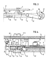
- One of the means for holding and firmly pinning serves on the slide 9 to frame 12 formed on the front side of the data cards 6 as a version. Furthermore, several hold-down devices are provided, of which in Figure 1 two, 13 and 14, are visible. Grippers 15 and 16, which in Interaction with the frame 12 on the data card 6 in the direction of the arrow hold the carriage 9 are movable on a cross to the carriage 9 Slider 17 ( Figure 4) formed. The latter is part of the tipping gear spring-mounted on the slide 9 and holds, as already mentioned and in Figure 1 shown in the one stable position on the carriage 9th located data card 6 by gripping sideways.
- a thrust member 20 which is actuated by a motor, serves by having a sliding surface 21 on a slide 9 associated with it Pin 22 engages, moving the carriage 9 in the input / removal position. An additional movement of the thrust member 20 triggers subsequently the toggle mechanism, with one on the slide 9 slidably mounted slide 23 acts.
- the carriage 9 in the cheeks 5th trained grooves 24 is guided, with individual on the carriage 9th trained strip elements engage in the grooves 24.
- a last element is denoted by 25 in FIG. 2 and another by 26 in FIG.
- a closing element 27 is used, which is rotatably mounted in the cheeks 5 as a segmented drum with at least one cylinder segment 29 formed between flanges 28.
- a crank 31 is integrally formed on the bearing journal 30 of the closing element 27 in order to be able to drive the closing element 27 on one side or on the other side.
- a push crank 32 is articulated, which is in geared connection with a push rod 33. The latter is held directly on the cheek 5 and guided in a suitable manner. That is to say, a groove 34 (FIG.
- FIG. 2 2) is provided on the one hand for guiding the flat-profiled push rod 33, and on the other hand consoles (not shown) are formed on the cheek 5, within which the securing hooks embracing the push rod 33 are free.
- the two securing hooks shown in Figure 1 are designated 35 and 36.
- 37 represents a housing of a light barrier attached to the cheek 5.
- a flag 38 actuating the light barrier is formed on the push rod 33.
- a two-armed bolt 39 is also mounted, which interacts with a fixed component 40, for example fastened to the printed circuit board 2, and is under the action of a spring 41.
- the axial securing of the mounting of the bolt 39 is carried out by means of a holder 42 fastened on the push rod 33, which additionally serves to hold one end of a tension spring 43 assigned to the push rod 33.
- the other end of the tension spring 43 is hooked onto a finger 44 formed on the cheek 5.
- a release of the lock between the bolt 39 and the component 40 and thus a release of the input / output opening of the read / write unit must be carried out immediately before the release of a data card 6, so that the drive of an actuating element symbolized by the arrow P is expediently synchronous should be done with the drive of the thrust member 20.
- the push rod 33 is T-shaped at one end.
- a bore designated 52 is provided in order to mount the bolt 39 in mirror image and thus also to be able to assign the push rod 33 to one or the other cheek 5 of a read / write unit, for the sake of completeness it should also be mentioned that instead of the drum-shaped closing element 27, a differently designed closing element, for example a flat slide or a pivotable flap, is provided It is essential that the closing element be in a suitable th gear connection with the push rod 33 is.
Landscapes
- Physics & Mathematics (AREA)
- General Physics & Mathematics (AREA)
- Lock And Its Accessories (AREA)
- Conveying Record Carriers (AREA)
Applications Claiming Priority (2)
| Application Number | Priority Date | Filing Date | Title |
|---|---|---|---|
| DE29822141U | 1998-12-11 | ||
| DE29822141U DE29822141U1 (de) | 1998-12-11 | 1998-12-11 | Anordnung zum Betätigen einer der Eingabe-/Ausgabeöffnung eines Lese-/Schreibaggregates für Datenkarten zugeordneten Schließelementes |
Publications (3)
| Publication Number | Publication Date |
|---|---|
| EP1008964A2 true EP1008964A2 (fr) | 2000-06-14 |
| EP1008964A3 EP1008964A3 (fr) | 2004-11-17 |
| EP1008964B1 EP1008964B1 (fr) | 2007-10-17 |
Family
ID=8066526
Family Applications (1)
| Application Number | Title | Priority Date | Filing Date |
|---|---|---|---|
| EP19990124274 Expired - Lifetime EP1008964B1 (fr) | 1998-12-11 | 1999-12-04 | Dispositif pour actionner un élément de fermeture d'une ouverture d'entrée/sortie d'une unité de lecture/écriture pour cartes de données |
Country Status (2)
| Country | Link |
|---|---|
| EP (1) | EP1008964B1 (fr) |
| DE (2) | DE29822141U1 (fr) |
Families Citing this family (1)
| Publication number | Priority date | Publication date | Assignee | Title |
|---|---|---|---|---|
| DE29904801U1 (de) * | 1999-03-16 | 1999-06-02 | Mannesmann VDO AG, 60388 Frankfurt | Lese-/Schreibaggregat für Datenkarten |
Family Cites Families (5)
| Publication number | Priority date | Publication date | Assignee | Title |
|---|---|---|---|---|
| US4724310A (en) * | 1984-07-02 | 1988-02-09 | Tokyo Tatsuno Co., Ltd. | Device for inserting and holding an IC card as an external memory during reading and writing operations |
| ATE182999T1 (de) * | 1988-10-14 | 1999-08-15 | Omron Tateisi Electronics Co | Kartenlesegerät mit verriegelung |
| JPH0652542B2 (ja) * | 1989-07-27 | 1994-07-06 | 株式会社田村電機製作所 | カードリーダのシヤツタ機構 |
| JPH0810459B2 (ja) * | 1990-02-28 | 1996-01-31 | アンリツ株式会社 | カード取込み装置 |
| DE4428276C2 (de) * | 1994-08-10 | 2000-07-06 | Mannesmann Vdo Ag | Datenkartenaufnahme |
-
1998
- 1998-12-11 DE DE29822141U patent/DE29822141U1/de not_active Expired - Lifetime
-
1999
- 1999-12-04 EP EP19990124274 patent/EP1008964B1/fr not_active Expired - Lifetime
- 1999-12-04 DE DE59914527T patent/DE59914527D1/de not_active Expired - Lifetime
Also Published As
| Publication number | Publication date |
|---|---|
| DE29822141U1 (de) | 1999-02-04 |
| EP1008964A3 (fr) | 2004-11-17 |
| DE59914527D1 (de) | 2007-11-29 |
| EP1008964B1 (fr) | 2007-10-17 |
Similar Documents
| Publication | Publication Date | Title |
|---|---|---|
| EP0186737B1 (fr) | Dispositif d'introduction d'une carte de données à circuit électronique | |
| DE4010398C2 (fr) | ||
| EP0114246A2 (fr) | Appareil à bande magnétique | |
| DE29812766U1 (de) | Hybrid-Kartenleser für IC-Karten/Magnetkarten | |
| DD149729A5 (de) | Magnetbandkassette und geraet dafuer | |
| EP1570416A1 (fr) | Logement pour carte a puce equipe d'un ejecteur et d'au moins un bras de verrouillage relie a ce dernier | |
| EP0940765B1 (fr) | Appareil pour le transport de cartes de données | |
| EP1184667B1 (fr) | Tachygraphe avec deux unités de lecture/écriture pour cartes de données agencées dans un plan | |
| EP0831001A1 (fr) | Rancher pour une bache | |
| DE8802877U1 (de) | Motorisierte Schere mit autonomer Speisung | |
| DE10321233A1 (de) | Drucker | |
| DE1244110B (de) | Merkblattregister | |
| EP1008964B1 (fr) | Dispositif pour actionner un élément de fermeture d'une ouverture d'entrée/sortie d'une unité de lecture/écriture pour cartes de données | |
| DE10208259A1 (de) | Chipkarten-Aufnahmevorrichtung mit einem eine Chipkarte halternden Schlitten | |
| EP0899676B1 (fr) | Réceptacle de faible épaisseur pour cartes de données | |
| DE3145705C2 (de) | Vorrichtung zum Auslesen und/oder Einspeichern einer Information aus beziehungsweise in eine einen Speicher für die Information aufweisende, während des Informationsaustausches feststehende Karte | |
| EP1017013B1 (fr) | Dispositif de verrouillage pour un appareil de lecture/écriture de cartes de données | |
| EP2153372B1 (fr) | Appareil electrique muni d'un systeme de verrouillage pour support de donnees et procede de deverrouillage d'un support de donnees | |
| EP0935220A2 (fr) | Tachygraphe avec un boítier parallélépipédique | |
| DE3732892C2 (fr) | ||
| DE3153177C1 (en) | Device for reading-out and/or storing an information from or respectively in a card exhibiting a memory for the information and being stationary during the exchange of information | |
| EP1037161B1 (fr) | Unité de lecture/écriture pour cartes de données | |
| DE7828214U1 (de) | Verschluss zum verbinden von sicherheitsgurten | |
| DE3500986A1 (de) | Vorrichtung zur ein- und ausgabe von flaechigen aufzeichnungstraegern | |
| WO1997031326A1 (fr) | Lecteur hybride en trois dimensions surveille (lecteur maresch) |
Legal Events
| Date | Code | Title | Description |
|---|---|---|---|
| PUAI | Public reference made under article 153(3) epc to a published international application that has entered the european phase |
Free format text: ORIGINAL CODE: 0009012 |
|
| AK | Designated contracting states |
Kind code of ref document: A2 Designated state(s): AT BE CH CY DE DK ES FI FR GB GR IE IT LI LU MC NL PT SE |
|
| AX | Request for extension of the european patent |
Free format text: AL;LT;LV;MK;RO;SI |
|
| RAP1 | Party data changed (applicant data changed or rights of an application transferred) |
Owner name: SIEMENS AKTIENGESELLSCHAFT |
|
| PUAL | Search report despatched |
Free format text: ORIGINAL CODE: 0009013 |
|
| AK | Designated contracting states |
Kind code of ref document: A3 Designated state(s): AT BE CH CY DE DK ES FI FR GB GR IE IT LI LU MC NL PT SE |
|
| AX | Request for extension of the european patent |
Extension state: AL LT LV MK RO SI |
|
| 17P | Request for examination filed |
Effective date: 20041220 |
|
| 17Q | First examination report despatched |
Effective date: 20050606 |
|
| AKX | Designation fees paid |
Designated state(s): DE FR GB NL SE |
|
| GRAP | Despatch of communication of intention to grant a patent |
Free format text: ORIGINAL CODE: EPIDOSNIGR1 |
|
| GRAS | Grant fee paid |
Free format text: ORIGINAL CODE: EPIDOSNIGR3 |
|
| GRAA | (expected) grant |
Free format text: ORIGINAL CODE: 0009210 |
|
| AK | Designated contracting states |
Kind code of ref document: B1 Designated state(s): DE FR GB NL SE |
|
| REG | Reference to a national code |
Ref country code: GB Ref legal event code: FG4D Free format text: NOT ENGLISH |
|
| RAP2 | Party data changed (patent owner data changed or rights of a patent transferred) |
Owner name: SIEMENS VDO AUTOMOTIVE AG |
|
| REF | Corresponds to: |
Ref document number: 59914527 Country of ref document: DE Date of ref document: 20071129 Kind code of ref document: P |
|
| REG | Reference to a national code |
Ref country code: SE Ref legal event code: TRGR |
|
| NLT2 | Nl: modifications (of names), taken from the european patent patent bulletin |
Owner name: SIEMENS VDO AUTOMOTIVE AG Effective date: 20071128 |
|
| RAP2 | Party data changed (patent owner data changed or rights of a patent transferred) |
Owner name: VDO AUTOMOTIVE AG |
|
| ET | Fr: translation filed | ||
| REG | Reference to a national code |
Ref country code: FR Ref legal event code: TP |
|
| NLT2 | Nl: modifications (of names), taken from the european patent patent bulletin |
Owner name: VDO AUTOMOTIVE AG Effective date: 20080319 |
|
| RAP2 | Party data changed (patent owner data changed or rights of a patent transferred) |
Owner name: CONTINENTAL AUTOMOTIVE GMBH |
|
| PLBE | No opposition filed within time limit |
Free format text: ORIGINAL CODE: 0009261 |
|
| STAA | Information on the status of an ep patent application or granted ep patent |
Free format text: STATUS: NO OPPOSITION FILED WITHIN TIME LIMIT |
|
| NLT2 | Nl: modifications (of names), taken from the european patent patent bulletin |
Owner name: CONTINENTAL AUTOMOTIVE GMBH Effective date: 20080716 |
|
| 26N | No opposition filed |
Effective date: 20080718 |
|
| PGFP | Annual fee paid to national office [announced via postgrant information from national office to epo] |
Ref country code: GB Payment date: 20121220 Year of fee payment: 14 Ref country code: SE Payment date: 20121220 Year of fee payment: 14 |
|
| PGFP | Annual fee paid to national office [announced via postgrant information from national office to epo] |
Ref country code: DE Payment date: 20121231 Year of fee payment: 14 Ref country code: FR Payment date: 20130130 Year of fee payment: 14 |
|
| PGFP | Annual fee paid to national office [announced via postgrant information from national office to epo] |
Ref country code: NL Payment date: 20121220 Year of fee payment: 14 |
|
| REG | Reference to a national code |
Ref country code: DE Ref legal event code: R119 Ref document number: 59914527 Country of ref document: DE |
|
| REG | Reference to a national code |
Ref country code: NL Ref legal event code: V1 Effective date: 20140701 |
|
| REG | Reference to a national code |
Ref country code: SE Ref legal event code: EUG |
|
| GBPC | Gb: european patent ceased through non-payment of renewal fee |
Effective date: 20131204 |
|
| PG25 | Lapsed in a contracting state [announced via postgrant information from national office to epo] |
Ref country code: SE Free format text: LAPSE BECAUSE OF NON-PAYMENT OF DUE FEES Effective date: 20131205 |
|
| REG | Reference to a national code |
Ref country code: FR Ref legal event code: ST Effective date: 20140829 |
|
| REG | Reference to a national code |
Ref country code: DE Ref legal event code: R119 Ref document number: 59914527 Country of ref document: DE Effective date: 20140701 |
|
| PG25 | Lapsed in a contracting state [announced via postgrant information from national office to epo] |
Ref country code: DE Free format text: LAPSE BECAUSE OF NON-PAYMENT OF DUE FEES Effective date: 20140701 Ref country code: NL Free format text: LAPSE BECAUSE OF NON-PAYMENT OF DUE FEES Effective date: 20140701 |
|
| PG25 | Lapsed in a contracting state [announced via postgrant information from national office to epo] |
Ref country code: FR Free format text: LAPSE BECAUSE OF NON-PAYMENT OF DUE FEES Effective date: 20131231 Ref country code: GB Free format text: LAPSE BECAUSE OF NON-PAYMENT OF DUE FEES Effective date: 20131204 |