EP1009686B1 - Device for connecting multiple isocontainers - Google Patents
Device for connecting multiple isocontainers Download PDFInfo
- Publication number
- EP1009686B1 EP1009686B1 EP97935908A EP97935908A EP1009686B1 EP 1009686 B1 EP1009686 B1 EP 1009686B1 EP 97935908 A EP97935908 A EP 97935908A EP 97935908 A EP97935908 A EP 97935908A EP 1009686 B1 EP1009686 B1 EP 1009686B1
- Authority
- EP
- European Patent Office
- Prior art keywords
- container
- containers
- aperture
- sealing
- land surface
- Prior art date
- Legal status (The legal status is an assumption and is not a legal conclusion. Google has not performed a legal analysis and makes no representation as to the accuracy of the status listed.)
- Expired - Lifetime
Links
- 238000007789 sealing Methods 0.000 claims abstract description 50
- 239000007788 liquid Substances 0.000 claims abstract description 4
- 239000000463 material Substances 0.000 claims 1
- 230000008719 thickening Effects 0.000 claims 1
- 230000000717 retained effect Effects 0.000 abstract 1
- 238000010276 construction Methods 0.000 description 7
- 229910000831 Steel Inorganic materials 0.000 description 2
- 208000015181 infectious disease Diseases 0.000 description 2
- 238000000034 method Methods 0.000 description 2
- 238000003825 pressing Methods 0.000 description 2
- 239000010959 steel Substances 0.000 description 2
- 230000008878 coupling Effects 0.000 description 1
- 238000010168 coupling process Methods 0.000 description 1
- 238000005859 coupling reaction Methods 0.000 description 1
- 230000001419 dependent effect Effects 0.000 description 1
- 230000000694 effects Effects 0.000 description 1
- 230000002458 infectious effect Effects 0.000 description 1
- 238000005304 joining Methods 0.000 description 1
- 238000003860 storage Methods 0.000 description 1
- 238000013022 venting Methods 0.000 description 1
- 239000011800 void material Substances 0.000 description 1
- 238000004073 vulcanization Methods 0.000 description 1
- 238000003466 welding Methods 0.000 description 1
Images



Classifications
-
- E—FIXED CONSTRUCTIONS
- E04—BUILDING
- E04B—GENERAL BUILDING CONSTRUCTIONS; WALLS, e.g. PARTITIONS; ROOFS; FLOORS; CEILINGS; INSULATION OR OTHER PROTECTION OF BUILDINGS
- E04B1/00—Constructions in general; Structures which are not restricted either to walls, e.g. partitions, or floors or ceilings or roofs
- E04B1/348—Structures composed of units comprising at least considerable parts of two sides of a room, e.g. box-like or cell-like units closed or in skeleton form
- E04B1/34815—Elements not integrated in a skeleton
- E04B1/3483—Elements not integrated in a skeleton the supporting structure consisting of metal
-
- B—PERFORMING OPERATIONS; TRANSPORTING
- B61—RAILWAYS
- B61D—BODY DETAILS OR KINDS OF RAILWAY VEHICLES
- B61D45/00—Means or devices for securing or supporting the cargo, including protection against shocks
- B61D45/007—Fixing containers
-
- B—PERFORMING OPERATIONS; TRANSPORTING
- B65—CONVEYING; PACKING; STORING; HANDLING THIN OR FILAMENTARY MATERIAL
- B65D—CONTAINERS FOR STORAGE OR TRANSPORT OF ARTICLES OR MATERIALS, e.g. BAGS, BARRELS, BOTTLES, BOXES, CANS, CARTONS, CRATES, DRUMS, JARS, TANKS, HOPPERS, FORWARDING CONTAINERS; ACCESSORIES, CLOSURES, OR FITTINGS THEREFOR; PACKAGING ELEMENTS; PACKAGES
- B65D90/00—Component parts, details or accessories for large containers
- B65D90/008—Doors for containers, e.g. ISO-containers
Definitions
- the invention concerns a device for connecting ISO type freight containers, as described in the introductory of patent claim 1.
- Freight containers simply referred to as 'containers', are in extensive use for both civil and military storage and/or transportation of different types of items by sea, train, container trucks or aircrafts etc.
- the containers are constructed by a framework of steel having a floor, side walls and roof of flat or profiled plates. Usually the containers are provided with swing doors at one of the short ends.
- US Patent 3,061,134 describes a container which has a construction for singular use and for use as a combination of two container units connected end to end. This is obtained by providing an end surface of the container unit with a ribbon-shaped sealing means 35 encircling the aperture of the front door 21 of the container unit. Moreover, the front door exhibits stop means 36 having an extension corresponding to the sealing means to decrease pressing load to the sealing means 35 and to protect the latter from mechanical load both in a mounted situation and in a free-standing situation.
- a substantially correspondingly shaped second container unit is guided towards a first container unit to establish surface contact between their respective sealing means 35 and stop means 36.
- the container units are kept together in such a surface to surface contact by means of locking means 42 arranged at the comers of the aperture, in which the respective locking means 42 in general comprises a bar 43 extending through a bore at the edge of the front door, a locking pin 61 to lock the bolt within the bore including lever 56 to bring the bar 43 from a locked to an open state, and conversely.
- the (relatively narrow) sealing 35 is established only at the contacting surface of the respective container units.
- This design in combination with the stop means 36 requires an exact positioning of the container units in a connecting procedure.
- the combination of the sealing 35 and stop means 36 is not expected to offer a sufficient sealing effect to establish a sufficient overpressure or underpressure within the internal container space.
- Another substantial difference between this prior art construction from the present invention is that the locking or clamping means 42 exhibits a relatively long physical extension and will therefore extend partly into the aperture established after the connection. Accordingly, a design of this type will strongly limit the possibilities of establishing a free passage, for example, through the connected containers.
- the prior art construction is not at all suited for connecting any form of a connection between more than two containers.
- the object of the invention is to provide a device for connecting containers of this type in a convenient and low-cost manner, such that the connected containers are sealed against unchecked interchange of gas/liquid between the internal container space and the surrounding atmosphere.
- Another object of the present invention is to provide a device allowing the containers to be used as a transport container device before and after their use as a building.
- the device in accordance with the invention is applicable to both civil and military use.
- the invention enables assembly of containers of this type and, for example, establishing a hospital, a workshop or command central, of a practically unlimited size.
- the assembly principle of the containers also renders it possible to establish overpressure within the building block as a whole, thus supplying sterile filtered air to a operating room via a fan/filter arrangement arranged within or in connection with the container block.
- a container block can be provided with an underpressure by means of an accompanying fan/air filter arrangement.
- an accompanying fan/air filter arrangement In this way it is possible to establish a solitary confinement, for example, for keeping infection sources, such as infected persons from epidemic areas in a simple and low-cost manner.
- Exchange of infectious patients to and from an isolate block of this type can be done in a convenient manner with a single freight container, shaped in accordance with the invention and provided with a separate fan/filter arrangement to establish underpressure within the same, at connection and disconnection via a lock system connected with the container block shaped with a similar sealing connecting device.
- the containers are preferably in advance prepared for a combined use by mounting canal sections for venting, signal and power supply mains etc.
- These component parts are preferably mounted in accordance with a standarised pattern of different types of modules and are, at the respective ends of each container wall, provided with different coupling means, e.g. plugs, sockets etc. enabling a fast connection of power and signal supply mains and canal mains to a corresponding segment within an adjacent container.
- These canal sections are arranged to extend through the sealed aperture in adjoining containers.
- temporary walls of tear resistant and pressure resistant canvas may be connected to the open wall sections of the container in question after use.
- Figure 1 is a drawing showing an imagined building block assembled by means of the device in accordance with the invention formed of a tot of nine freight containers 101, 102, 103, 104, 105, 106, 107, 108 and 109, in which container 109 constitutes the entrance section of the building block.
- the room grouping can be selected arbitrarily, and in Figure 1 there has been established one large compartment of four containers (102, 103, 105 and 106), one some smaller compartment of two containers (104 and 107), whereas the remaining containers each form one single compartment.
- Admittance to each of the compartments is provided with doors.
- the building block has been provided with only one entrance door in container 109, and is not provided with any window to the external surroundings.
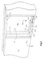
- Figure 2 shows a section of a first 101 and a second 102 adjacent container.
- a recess 10 in the wall is provided to establish a passage between the first and second container 101, 102.
- the recess can be shaped in, e.g., the shortest container wall, the longest container wall, or within a segment of the same, whereby an opposite container is formed with a recess having a similar size.
- the floor in the respective containers are indicated at 101 a for the first container 101 and at 102a for the second container 102.
- the open area between the containers is indicated at 20 and represents the void between adjacent containers to be covered up and sealed with the device in accordance with the invention.
- the recess 10 is provided with support means 401 arranged at the horizontal lower part of the aperture 10 in the first container 101 and a corresponding support means 451 at the horisontal lower part of the aperture 10 in the second container 102.
- the lower part of the support means, or the part of the same constituting a part of the container door sill, is preferably countersunk into the container floor to establish an aperture between the containers level with the floor of the same.
- the support means each exhibit a substantially vertical surface 402 and 452, respectively, extending substantially in parallel with the wall of the respective container 101, 102, and is intended to establish a land surface for the sealing means in a direction towards the internal section of the appropriate container, as is apparent in further detail below in connection with Fig. 3 and 4.
- Similar support means are arranged at the side edges of the aperture and at the upper part of the aperture, here - for simplicity - only indicated by numeral reference 411 in the upper part of the aperture of the first container 101, and the support means then forms an internal frame encircling the aperture to be sealed.
- the support means can be formed by separate modules, or can be formed as a rectangular or square integral frame, and can be connected to the container in any suitable manner, such as with bolts, screws or by welding.
- Figure 3 is a drawing similar to Figure 2 except that a ribbon-shaped sealing means 201 is arranged onto the joint section in the aperture 10 between the respective containers 101 and 102.
- the sealing means 201 exhibits a first elongate edge 201a and a second elongate edge 201b, wherein the first elongate edge is folded about the corner of the aperture of the first container 101.
- the second elongate edge 201b of the sealing means is similarly folded about the comer of the aperture of the second container 102, and the central section of the sealing means 201 accordingly covers the cross section surface of the aperture 10 between the containers.
- the first elongate edge 201a of the sealing means 201 rests against the vertical surface 402 of the support means 401.
- Each of the support means preferably includes a horizontal surface 403, 453 establishing a support surface for the central section of the sealing means 201 to the respective elongate edges to prevent damage to the sealing means. Accordingly, in a connected state the sealing means will embed the doorway completely in both containers. It should be noted that the figure for simplicity shows a partial section.
- Figure 4 shows the fixing of the sealing means illustrated in Figure 3, in which a first and second clamping means 301 and 351, respectively, comprising a rectangular frame 301 formed of angle steel, for example, has been pressed into the respective surfaces of the doorway. Then a press surface 302, formed by one angle segment within the frame profile extending in parallel with the main level of the frame, rests against the elongate edge 201 a (not seen in Figure 4) of the sealing means, and a protecting surface formed by the second angle segment 303 of the frame profile extending perpendicularly to the main level of the frame extends into the center of the joint area between the containers.
- the protecting surface 303 preferably exhibits a width of approximately half the width of the aperture 10 between the containers 101 and 102.
- a cover plate (not illustrated) can be inserted in the open area between the clamping means 301 and 351 at the underside of the respective protecting surfaces 303 and 353 and at the external side of the inserted sealing means 201.
- Fastening means 600 fixed in a first retaining means is arranged to force the first and second clamping means, respectively, towards each other, whereby the sealing means is jammed between the container wall and clamping means at each side of the doorway.
- the fastening means can be of any type known per se, to press and retain two items against each other, such as eccentric locks or similar to clamp two separate objects together, and are arranged preferably at each corner of the clamping means or distributed evenly along the perimeter of the same.
- the fastening means does not have to force the retaining means towards each other; it is also conceivable to use clamping means pressing against the press surface to force the underlying sealing means towards the respective land surface. Then, the sealing means is jammed between the vertical surface 402 (land surface) of the support 401 and the press surface 302 of the clamping means 301. In this way a gas-tight construction is achievable by simple means.
- Figure 5 is a cross-section taken along the line 5-5 of Figure 4 and shows the floor 101a of the first container 101 and the floor 102a of the second container 102.
- Angle sections 401 and 451 are fixedly connected to the floor of the respective containers 101 and 102, establishing support for the sealing means 201.
- the lower part of the land surface 402 and 452 of the respective supports are in this embodiment welded to the floor 101a and 102a of said first and second container, respectively, by a solid-drawn seam.
- the supports can also be fixed by means of another arrangment, such as bolts or screws. In the latter alternative, a sufficient sealing to gas/liquid will have to be established in the joint between the support and the container.
- a further description of the construction is set forth below.
- Figure 6 illustrates a cross section of an alternative embodiment of the sealing means 201, in which the respective elongate edges 201a and 201b are formed with a thickened section 202a and 202b, respectively, intended to facilitate the sealing between the containers.
- a thickened section 202a and 202b At the inside of the respective thickened sections towards the center of the sealing means there is established an incision 203a and 203b facilitating folding of the sealing means about the support 401 and 451, respectively.
- the sealing means may alternatively be formed with a U-shaped cross section adapted to the external geometry of the support.
- the sealing means can be provided separately or be integral with the support or the clamping means, and can be formed as a closed loop having dimensions adapted to the aperture to be sealed, or can be cut to a desired length for a subsequent joining, such as vulcanization, in the assembly procedure of the sealing means to the support.
- the invention also comprises a support plate.
- Figure 7a illustrates a substantially level support plate, in this embodiment square, provided with four protrusions 511, 512, 513 and 514 arranged about the center of the plate 501.
- the protrusions exhibit a substantially rectangular cross section and a preferably pointed end.
- Figure 7b shows the support plate 501 in use arranged under two containers 101 and 102.
- the protrusions 513 and 514 extend in at least partly into recesses 101b and 102b formed in the underside of the corner of the respective containers 101 and 102.
- a support plate 501 is located under each of the four comers of a first container having one of its protrusions 511 extending into the recess 101b of the underside of the comers of the first container.
- the protrusions 514 will first serve as a control or guiding means to guide subsequent containers down upon the support plate and against an existing container.
- the protrusions will serve as support or retaining means securing a steady positioning of the containers.
- the present invention accordingly provides a device which enables rapid and low-cost establisment of a larger building block, which can be provided with an underpressure or overpressure to the surrounding atmosphere.
- the flexible sealing connection between adjacent containers also enables the establishment of a building block of this type upon an uneven base.
Landscapes
- Engineering & Computer Science (AREA)
- Architecture (AREA)
- Mechanical Engineering (AREA)
- Electromagnetism (AREA)
- Civil Engineering (AREA)
- Structural Engineering (AREA)
- Transportation (AREA)
- Physics & Mathematics (AREA)
- Pallets (AREA)
- Stackable Containers (AREA)
- Load-Engaging Elements For Cranes (AREA)
- Supplying Of Containers To The Packaging Station (AREA)
- Packages (AREA)
- Closures For Containers (AREA)
- Pressure Vessels And Lids Thereof (AREA)
- Accommodation For Nursing Or Treatment Tables (AREA)
- Building Environments (AREA)
- Vacuum Packaging (AREA)
- Quick-Acting Or Multi-Walled Pipe Joints (AREA)
- Ship Loading And Unloading (AREA)
- Arc Welding In General (AREA)
- Pressure Welding/Diffusion-Bonding (AREA)
- Superconductors And Manufacturing Methods Therefor (AREA)
- Joining Of Building Structures In Genera (AREA)
- Mutual Connection Of Rods And Tubes (AREA)
Applications Claiming Priority (3)
| Application Number | Priority Date | Filing Date | Title |
|---|---|---|---|
| NO963263A NO963263D0 (no) | 1996-08-05 | 1996-08-05 | Anordning for sammenföyning av isocontainere |
| NO963263 | 1996-08-05 | ||
| PCT/NO1997/000198 WO1998005574A1 (en) | 1996-08-05 | 1997-08-05 | Device for connecting multiple isocontainers |
Publications (2)
| Publication Number | Publication Date |
|---|---|
| EP1009686A1 EP1009686A1 (en) | 2000-06-21 |
| EP1009686B1 true EP1009686B1 (en) | 2003-02-26 |
Family
ID=19899676
Family Applications (1)
| Application Number | Title | Priority Date | Filing Date |
|---|---|---|---|
| EP97935908A Expired - Lifetime EP1009686B1 (en) | 1996-08-05 | 1997-08-05 | Device for connecting multiple isocontainers |
Country Status (15)
| Country | Link |
|---|---|
| US (1) | US6102228A (pl) |
| EP (1) | EP1009686B1 (pl) |
| JP (1) | JP2000515939A (pl) |
| AT (1) | ATE233219T1 (pl) |
| AU (1) | AU3870697A (pl) |
| CA (1) | CA2263079C (pl) |
| CZ (1) | CZ293159B6 (pl) |
| DE (1) | DE69719381T2 (pl) |
| DK (1) | DK1009686T3 (pl) |
| HU (1) | HUP0103087A3 (pl) |
| IL (1) | IL128272A0 (pl) |
| NO (1) | NO963263D0 (pl) |
| PL (1) | PL184636B1 (pl) |
| TR (1) | TR199900226T2 (pl) |
| WO (1) | WO1998005574A1 (pl) |
Families Citing this family (10)
| Publication number | Priority date | Publication date | Assignee | Title |
|---|---|---|---|---|
| NO974828A (no) * | 1997-10-17 | 1999-01-18 | Shelter Dev As | Anordning for sammenkopling av containere |
| US7198924B2 (en) | 2000-12-11 | 2007-04-03 | Invitrogen Corporation | Methods and compositions for synthesis of nucleic acid molecules using multiple recognition sites |
| US8304189B2 (en) | 2003-12-01 | 2012-11-06 | Life Technologies Corporation | Nucleic acid molecules containing recombination sites and methods of using the same |
| US7762025B2 (en) * | 2004-11-19 | 2010-07-27 | Modular Security Systems, Inc. | Containerized access control system |
| US20070138173A1 (en) * | 2006-06-30 | 2007-06-21 | Flex Box Ltd. | Storage container and method of forming same |
| US7823338B2 (en) * | 2007-04-10 | 2010-11-02 | Modular Security Systems, Inc. | Modular access control system |
| US20080282631A1 (en) * | 2007-05-17 | 2008-11-20 | Anna Joke Breimer | Building Unit, Method for Assembling a Building Unit, Method for Transporting a Building Unit |
| KR101346791B1 (ko) | 2013-05-15 | 2014-01-03 | 주식회사 얼반테이너 | 컨테이너 및 컨테이너 접합 구조체 |
| US9003716B1 (en) * | 2014-01-06 | 2015-04-14 | Kwikspace Guam | Wind resistant modular ISO building |
| US10000939B1 (en) * | 2014-01-06 | 2018-06-19 | Kwikspace Guam | Single container wind resistant modular ISO building |
Family Cites Families (11)
| Publication number | Priority date | Publication date | Assignee | Title |
|---|---|---|---|---|
| US3061134A (en) * | 1960-11-14 | 1962-10-30 | Budd Co | Cargo containers |
| HU174468B (hu) * | 1975-12-28 | 1980-01-28 | Magyar Hajo Es Darugyar | Prostranstvennye ehlementy dlja postrojki odno- ili mnogoehtazhnykh domov, ispolzuemye pri vozvedenii vremennykh i/ili bystrovozvodimykh zdanij |
| ZA767590B (en) * | 1976-01-16 | 1978-07-26 | Powell Mfg Co | A portable section of a tobacco curing barn |
| US4576300A (en) * | 1984-07-03 | 1986-03-18 | Allegheny Ludlum Steel Corporation | Reusable shipping container |
| JPS63502745A (ja) * | 1986-02-21 | 1988-10-13 | ティ−シ−エス・コンテナ−ズ・プロプライアタリ−・リミテッド | 貨物用コンテナ |
| DE3800120A1 (de) * | 1988-01-05 | 1989-07-13 | Dieter Borchardt | Verfahren zum zusammenfassen von mindestens zwei lagen aus jeweils einer ungeradzahligen anzahl von iso-containern zu einer transporteinheit sowie transporteinheit |
| GB2246337A (en) * | 1990-07-28 | 1992-01-29 | Clive Smith Martin | Extension modules for freight containers |
| US5199589A (en) * | 1992-07-27 | 1993-04-06 | Noble William L | Collapsible bix box assembly formed of two separate collapsible bin boxes |
| AUPN006594A0 (en) * | 1994-12-14 | 1995-01-12 | Technosearch Pty. Limited | Improvements in containers |
| DE19501423A1 (de) * | 1995-01-19 | 1996-07-25 | Rsh Repair Service Hamburg Gmb | Transportabler Container |
| US5735639A (en) * | 1996-12-13 | 1998-04-07 | The United States Of America As Represented By The Secretary Of The Navy | Modular mobile safety structure for containment and handling of hazardous materials |
-
1996
- 1996-08-05 NO NO963263A patent/NO963263D0/no unknown
-
1997
- 1997-08-05 DK DK97935908T patent/DK1009686T3/da active
- 1997-08-05 WO PCT/NO1997/000198 patent/WO1998005574A1/en not_active Ceased
- 1997-08-05 PL PL97331413A patent/PL184636B1/pl not_active IP Right Cessation
- 1997-08-05 TR TR1999/00226T patent/TR199900226T2/xx unknown
- 1997-08-05 EP EP97935908A patent/EP1009686B1/en not_active Expired - Lifetime
- 1997-08-05 AU AU38706/97A patent/AU3870697A/en not_active Abandoned
- 1997-08-05 JP JP10507846A patent/JP2000515939A/ja not_active Ceased
- 1997-08-05 AT AT97935908T patent/ATE233219T1/de not_active IP Right Cessation
- 1997-08-05 HU HU0103087A patent/HUP0103087A3/hu unknown
- 1997-08-05 US US09/230,960 patent/US6102228A/en not_active Expired - Fee Related
- 1997-08-05 CZ CZ1999294A patent/CZ293159B6/cs not_active IP Right Cessation
- 1997-08-05 IL IL12827297A patent/IL128272A0/xx not_active IP Right Cessation
- 1997-08-05 CA CA002263079A patent/CA2263079C/en not_active Expired - Fee Related
- 1997-08-05 DE DE69719381T patent/DE69719381T2/de not_active Expired - Fee Related
Also Published As
| Publication number | Publication date |
|---|---|
| PL331413A1 (en) | 1999-07-19 |
| US6102228A (en) | 2000-08-15 |
| WO1998005574A1 (en) | 1998-02-12 |
| CZ9900294A3 (cs) | 2000-11-15 |
| DE69719381D1 (de) | 2003-04-03 |
| HUP0103087A3 (en) | 2002-02-28 |
| DK1009686T3 (da) | 2003-06-10 |
| HUP0103087A2 (hu) | 2001-12-28 |
| DE69719381T2 (de) | 2003-12-04 |
| NO963263D0 (no) | 1996-08-05 |
| PL184636B1 (pl) | 2002-11-29 |
| TR199900226T2 (xx) | 1999-06-21 |
| AU3870697A (en) | 1998-02-25 |
| ATE233219T1 (de) | 2003-03-15 |
| CZ293159B6 (cs) | 2004-02-18 |
| JP2000515939A (ja) | 2000-11-28 |
| IL128272A0 (en) | 1999-11-30 |
| EP1009686A1 (en) | 2000-06-21 |
| CA2263079C (en) | 2006-10-31 |
| CA2263079A1 (en) | 1998-02-12 |
Similar Documents
| Publication | Publication Date | Title |
|---|---|---|
| CA2263079C (en) | Device for connecting multiple isocontainers | |
| US20250019153A1 (en) | Laterally combinable multipurpose relocatable structures | |
| US20030011192A1 (en) | Locking mechanism for air handler (AHU) cabinet | |
| US5287813A (en) | Coach body construction for rail vehicles having extruded aluminum profiles with undercut nut-receiving grooves for ease of asssembly | |
| GR3023610T3 (en) | A foldable container. | |
| AU712249B2 (en) | Safety device | |
| US10622795B2 (en) | Transition for passage through a wall, and module | |
| US20230211943A1 (en) | Modular structure systems | |
| GB2343907A (en) | Flood damage prevention systems | |
| JP2020193517A (ja) | 持ち運び式止水板装置 | |
| US20150225973A1 (en) | Overseas vehicle segmented enclosure system | |
| US12487004B2 (en) | Interchangeable duct seal | |
| US6331090B1 (en) | Device for connecting containers | |
| CN211257326U (zh) | 密封结构及组合方舱 | |
| JPH08230983A (ja) | 防災備蓄コンテナ | |
| US20200309441A1 (en) | Modular Coolroom System and Coolroom Modules Therefor | |
| JP2002332753A (ja) | 前室ユニット | |
| CN223224999U (zh) | 拼接式近海型集装箱 | |
| CN211714678U (zh) | 组合式气密封异形方舱 | |
| GB2271595A (en) | Securement device | |
| AU2761100A (en) | Mine survival chamber | |
| CN119429431A (zh) | 拼接式近海型集装箱 | |
| GB2280696A (en) | Security closure for a doorway | |
| HU203057B (en) | Container for forming settled closed premise having larger volume than the original transporting volume | |
| CN113998264A (zh) | 一种模块化站台门转运、吊装装置 |
Legal Events
| Date | Code | Title | Description |
|---|---|---|---|
| PUAI | Public reference made under article 153(3) epc to a published international application that has entered the european phase |
Free format text: ORIGINAL CODE: 0009012 |
|
| 17P | Request for examination filed |
Effective date: 19990204 |
|
| AK | Designated contracting states |
Kind code of ref document: A1 Designated state(s): AT BE CH DE DK ES FI FR GB GR IE IT LI LU MC NL PT SE |
|
| GRAG | Despatch of communication of intention to grant |
Free format text: ORIGINAL CODE: EPIDOS AGRA |
|
| 17Q | First examination report despatched |
Effective date: 20020503 |
|
| GRAG | Despatch of communication of intention to grant |
Free format text: ORIGINAL CODE: EPIDOS AGRA |
|
| GRAH | Despatch of communication of intention to grant a patent |
Free format text: ORIGINAL CODE: EPIDOS IGRA |
|
| GRAH | Despatch of communication of intention to grant a patent |
Free format text: ORIGINAL CODE: EPIDOS IGRA |
|
| GRAA | (expected) grant |
Free format text: ORIGINAL CODE: 0009210 |
|
| AK | Designated contracting states |
Designated state(s): AT BE CH DE DK ES FI FR GB GR IE IT LI LU MC NL PT SE |
|
| PG25 | Lapsed in a contracting state [announced via postgrant information from national office to epo] |
Ref country code: NL Free format text: LAPSE BECAUSE OF FAILURE TO SUBMIT A TRANSLATION OF THE DESCRIPTION OR TO PAY THE FEE WITHIN THE PRESCRIBED TIME-LIMIT Effective date: 20030226 Ref country code: LI Free format text: LAPSE BECAUSE OF FAILURE TO SUBMIT A TRANSLATION OF THE DESCRIPTION OR TO PAY THE FEE WITHIN THE PRESCRIBED TIME-LIMIT Effective date: 20030226 Ref country code: IT Free format text: LAPSE BECAUSE OF FAILURE TO SUBMIT A TRANSLATION OF THE DESCRIPTION OR TO PAY THE FEE WITHIN THE PRE;WARNING: LAPSES OF ITALIAN PATENTS WITH EFFECTIVE DATE BEFORE 2007 MAY HAVE OCCURRED AT ANY TIME BEFORE 2007. THE CORRECT EFFECTIVE DATE MAY BE DIFFERENT FROM THE ONE RECORDED.SCRIBED TIME-LIMIT Effective date: 20030226 Ref country code: GR Free format text: LAPSE BECAUSE OF FAILURE TO SUBMIT A TRANSLATION OF THE DESCRIPTION OR TO PAY THE FEE WITHIN THE PRESCRIBED TIME-LIMIT Effective date: 20030226 Ref country code: FR Free format text: LAPSE BECAUSE OF NON-PAYMENT OF DUE FEES Effective date: 20030226 Ref country code: FI Free format text: LAPSE BECAUSE OF FAILURE TO SUBMIT A TRANSLATION OF THE DESCRIPTION OR TO PAY THE FEE WITHIN THE PRESCRIBED TIME-LIMIT Effective date: 20030226 Ref country code: CH Free format text: LAPSE BECAUSE OF FAILURE TO SUBMIT A TRANSLATION OF THE DESCRIPTION OR TO PAY THE FEE WITHIN THE PRESCRIBED TIME-LIMIT Effective date: 20030226 Ref country code: AT Free format text: LAPSE BECAUSE OF FAILURE TO SUBMIT A TRANSLATION OF THE DESCRIPTION OR TO PAY THE FEE WITHIN THE PRESCRIBED TIME-LIMIT Effective date: 20030226 |
|
| REG | Reference to a national code |
Ref country code: GB Ref legal event code: FG4D |
|
| REG | Reference to a national code |
Ref country code: CH Ref legal event code: EP |
|
| REG | Reference to a national code |
Ref country code: IE Ref legal event code: FG4D |
|
| REF | Corresponds to: |
Ref document number: 69719381 Country of ref document: DE Date of ref document: 20030403 Kind code of ref document: P |
|
| PG25 | Lapsed in a contracting state [announced via postgrant information from national office to epo] |
Ref country code: PT Free format text: LAPSE BECAUSE OF FAILURE TO SUBMIT A TRANSLATION OF THE DESCRIPTION OR TO PAY THE FEE WITHIN THE PRESCRIBED TIME-LIMIT Effective date: 20030526 |
|
| REG | Reference to a national code |
Ref country code: SE Ref legal event code: TRGR |
|
| REG | Reference to a national code |
Ref country code: DK Ref legal event code: T3 |
|
| NLV1 | Nl: lapsed or annulled due to failure to fulfill the requirements of art. 29p and 29m of the patents act | ||
| PG25 | Lapsed in a contracting state [announced via postgrant information from national office to epo] |
Ref country code: LU Free format text: LAPSE BECAUSE OF NON-PAYMENT OF DUE FEES Effective date: 20030805 Ref country code: IE Free format text: LAPSE BECAUSE OF NON-PAYMENT OF DUE FEES Effective date: 20030805 Ref country code: GB Free format text: LAPSE BECAUSE OF NON-PAYMENT OF DUE FEES Effective date: 20030805 |
|
| PG25 | Lapsed in a contracting state [announced via postgrant information from national office to epo] |
Ref country code: ES Free format text: LAPSE BECAUSE OF FAILURE TO SUBMIT A TRANSLATION OF THE DESCRIPTION OR TO PAY THE FEE WITHIN THE PRESCRIBED TIME-LIMIT Effective date: 20030828 |
|
| PG25 | Lapsed in a contracting state [announced via postgrant information from national office to epo] |
Ref country code: MC Free format text: LAPSE BECAUSE OF NON-PAYMENT OF DUE FEES Effective date: 20030831 |
|
| PLBE | No opposition filed within time limit |
Free format text: ORIGINAL CODE: 0009261 |
|
| STAA | Information on the status of an ep patent application or granted ep patent |
Free format text: STATUS: NO OPPOSITION FILED WITHIN TIME LIMIT |
|
| EN | Fr: translation not filed | ||
| 26N | No opposition filed |
Effective date: 20031127 |
|
| GBPC | Gb: european patent ceased through non-payment of renewal fee |
Effective date: 20030805 |
|
| REG | Reference to a national code |
Ref country code: IE Ref legal event code: MM4A |
|
| PGFP | Annual fee paid to national office [announced via postgrant information from national office to epo] |
Ref country code: DK Payment date: 20070815 Year of fee payment: 11 |
|
| PGFP | Annual fee paid to national office [announced via postgrant information from national office to epo] |
Ref country code: DE Payment date: 20070822 Year of fee payment: 11 |
|
| PGFP | Annual fee paid to national office [announced via postgrant information from national office to epo] |
Ref country code: SE Payment date: 20070815 Year of fee payment: 11 Ref country code: BE Payment date: 20070905 Year of fee payment: 11 |
|
| REG | Reference to a national code |
Ref country code: DK Ref legal event code: EBP |
|
| EUG | Se: european patent has lapsed | ||
| PG25 | Lapsed in a contracting state [announced via postgrant information from national office to epo] |
Ref country code: DK Free format text: LAPSE BECAUSE OF NON-PAYMENT OF DUE FEES Effective date: 20080831 Ref country code: BE Free format text: LAPSE BECAUSE OF NON-PAYMENT OF DUE FEES Effective date: 20080831 |
|
| PG25 | Lapsed in a contracting state [announced via postgrant information from national office to epo] |
Ref country code: DE Free format text: LAPSE BECAUSE OF NON-PAYMENT OF DUE FEES Effective date: 20090303 |
|
| PG25 | Lapsed in a contracting state [announced via postgrant information from national office to epo] |
Ref country code: SE Free format text: LAPSE BECAUSE OF NON-PAYMENT OF DUE FEES Effective date: 20080806 |