EP1010555A2 - Structure pour éclairer un pare-soleil - Google Patents
Structure pour éclairer un pare-soleil Download PDFInfo
- Publication number
- EP1010555A2 EP1010555A2 EP99117376A EP99117376A EP1010555A2 EP 1010555 A2 EP1010555 A2 EP 1010555A2 EP 99117376 A EP99117376 A EP 99117376A EP 99117376 A EP99117376 A EP 99117376A EP 1010555 A2 EP1010555 A2 EP 1010555A2
- Authority
- EP
- European Patent Office
- Prior art keywords
- sunvisor
- stay
- light guide
- holder
- illuminating
- Prior art date
- Legal status (The legal status is an assumption and is not a legal conclusion. Google has not performed a legal analysis and makes no representation as to the accuracy of the status listed.)
- Withdrawn
Links
- 238000003780 insertion Methods 0.000 claims description 27
- 230000037431 insertion Effects 0.000 claims description 27
- 238000006073 displacement reaction Methods 0.000 claims description 4
- 238000007796 conventional method Methods 0.000 description 9
- 238000005286 illumination Methods 0.000 description 6
- 239000004925 Acrylic resin Substances 0.000 description 1
- 229920000178 Acrylic resin Polymers 0.000 description 1
- 229920006328 Styrofoam Polymers 0.000 description 1
- 238000005452 bending Methods 0.000 description 1
- 238000012986 modification Methods 0.000 description 1
- 230000004048 modification Effects 0.000 description 1
- 239000008261 styrofoam Substances 0.000 description 1
Images


Classifications
-
- B—PERFORMING OPERATIONS; TRANSPORTING
- B60—VEHICLES IN GENERAL
- B60J—WINDOWS, WINDSCREENS, NON-FIXED ROOFS, DOORS, OR SIMILAR DEVICES FOR VEHICLES; REMOVABLE EXTERNAL PROTECTIVE COVERINGS SPECIALLY ADAPTED FOR VEHICLES
- B60J3/00—Antiglare equipment associated with windows or windscreens; Sun visors for vehicles
- B60J3/02—Antiglare equipment associated with windows or windscreens; Sun visors for vehicles adjustable in position
- B60J3/0204—Sun visors
- B60J3/0213—Sun visors characterised by the mounting means
- B60J3/0217—Brackets for mounting the sun visor support arm to the vehicle
-
- B—PERFORMING OPERATIONS; TRANSPORTING
- B60—VEHICLES IN GENERAL
- B60J—WINDOWS, WINDSCREENS, NON-FIXED ROOFS, DOORS, OR SIMILAR DEVICES FOR VEHICLES; REMOVABLE EXTERNAL PROTECTIVE COVERINGS SPECIALLY ADAPTED FOR VEHICLES
- B60J3/00—Antiglare equipment associated with windows or windscreens; Sun visors for vehicles
- B60J3/02—Antiglare equipment associated with windows or windscreens; Sun visors for vehicles adjustable in position
- B60J3/0204—Sun visors
- B60J3/0278—Sun visors structure of the body
- B60J3/0282—Sun visors structure of the body specially adapted for a courtesy mirror
-
- B—PERFORMING OPERATIONS; TRANSPORTING
- B60—VEHICLES IN GENERAL
- B60Q—ARRANGEMENT OF SIGNALLING OR LIGHTING DEVICES, THE MOUNTING OR SUPPORTING THEREOF OR CIRCUITS THEREFOR, FOR VEHICLES IN GENERAL
- B60Q3/00—Arrangement of lighting devices for vehicle interiors; Lighting devices specially adapted for vehicle interiors
- B60Q3/20—Arrangement of lighting devices for vehicle interiors; Lighting devices specially adapted for vehicle interiors for lighting specific fittings of passenger or driving compartments; mounted on specific fittings of passenger or driving compartments
- B60Q3/252—Sun visors
-
- B—PERFORMING OPERATIONS; TRANSPORTING
- B60—VEHICLES IN GENERAL
- B60Q—ARRANGEMENT OF SIGNALLING OR LIGHTING DEVICES, THE MOUNTING OR SUPPORTING THEREOF OR CIRCUITS THEREFOR, FOR VEHICLES IN GENERAL
- B60Q3/00—Arrangement of lighting devices for vehicle interiors; Lighting devices specially adapted for vehicle interiors
- B60Q3/60—Arrangement of lighting devices for vehicle interiors; Lighting devices specially adapted for vehicle interiors characterised by optical aspects
- B60Q3/62—Arrangement of lighting devices for vehicle interiors; Lighting devices specially adapted for vehicle interiors characterised by optical aspects using light guides
- B60Q3/64—Arrangement of lighting devices for vehicle interiors; Lighting devices specially adapted for vehicle interiors characterised by optical aspects using light guides for a single lighting device
Definitions
- the present invention relates to a structure for illuminating a sunvisor.
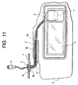
- a sunvisor is, as shown in Figs. 10 and 11, structured such that a horizontal shaft portion 3a of an L-shape pipe stay 3 having a vertical shaft portion 3a supported rotatively around the vertical shaft by a stay holder 2 joined to a roof panel 1 in a vehicle is inserted into a visor holder 5 of a sunvisor body 4.
- the sunvisor body 4 is supported movably in the vertical direction around a horizontal shaft.
- the sunvisor body 4 having a vanity mirror 6 is provided with a vanity lamp (an illuminating member) 7.
- a cover (not shown) of the vanity mirror 6 is opened, a switch is switched on so that the vanity lamp 7 is turned on.
- a sunvisor-body-side connector 9 joined to other ends of the electric wires 8 is, in the roof panel 1, connected to a car-body-side connector 11 connected to an electric wire 10 extended from a battery.
- the battery in the car body and the vanity lamp 7 of the sunvisor body are electrically connected to each other.
- each of the electric wires 8 is twisted to permit the movement of the sunvisor body 4.
- An operation for joining the stay holder 2, which supports the stay 3 of the sunvisor body 4, to the roof panel 1 is performed as follows: an operator holds the car-body-side connector 11 by either hand thereof while holding the sunvisor body 4 under the operator's arm in a state in which the car-body-side connector 11 has been drawn into the car body through a joining hole 1a of the roof panel 1. Then, the sunvisor-body-side connector 9 is held by the other hand so that the sunvisor-body-side connector 9 and the car-body-side connector 11 are connected to each other. Then, the sunvisor-body-side connector 9 and the electric wires 8 are pushed inwards into the inside portion of the roof panel 1 .
- an object of the present invention is to provide a structure for illuminating a sunvisor with which a variety of operations concerning illumination which is performed by an illuminating member provided for a sunvisor body can be simplified.
- a structure for illuminating a sunvisor structured such that a horizontal shaft portion of an L-shape stay having a vertical shaft portion supported rotatively around the vertical shaft by a stay holder joined to a roof panel in a vehicle is inserted into a visor holder of a sunvisor body so that the sunvisor body is supported movably in the vertical direction around a horizontal shaft and the sunvisor body is provided with an illuminating member, the structure for illuminating a sunvisor comprising:
- illuminating light emitted from the lamp of the lamp socket disposed in the roof panel is made incident on the incident end of the stay-side light guide at the end of the vertical shaft portion.
- Illuminating light emitted from the emission end of the stay-side light guide at the end of the horizontal shaft portion of the stay is introduced into the illuminating light guide through the sunvisor-side light guide.
- the illuminating light guide performs the illumination. Therefore, the necessity of passing the electric wires of the vanity lamp into the L-shape pipe stay can be eliminated. Hence it follows that the operation for passing the electric wires can be eliminated.
- the illuminating light guide is a frame-shape member which surrounds the outer surface of a vanity mirror joined to the sunvisor body, illumination from outside of the vanity mirror is permitted.
- the incident end of the sunvisor-side light guide is joined to the visor holder of the sunvisor body so that the emission end of the stay-side light guide at the end of the horizontal shaft portion is made to be opposite to the incident end of the sunvisor-side light guide when the horizontal shaft portion of the stay is inserted into the visor holder.
- the operation for inserting the horizontal shape portion of the stay into the visor holder can simply be completed by only making the emission end of the stay-side light guide at the end of the horizontal shaft portion to be opposite to the incident end of the sunvisor-side light guide. Therefore, the operation for connecting the connectors required for the conventional technique can be omitted.
- the vertical movement of the sunvisor body around the horizontal shaft does not require the sunvisor-side light guide to be rotated around the horizontal shaft.
- the lamp socket to which an electric wire extended from a battery is connected, is joined to a car-body member disposed in the roof panel so that the incident end of the stay-side light guide is made to be opposite to the lamp of the lamp socket when the stay holder which supports a stay-side end of the vertical shaft portion is joined to the roof panel.
- the operation for joining the socket holder to the roof panel can simply be completed by making the incident end of the stay-side light guide at the end of the vertical shaft to be opposite to the lamp of the lamp socket. Therefore, the operation for connecting the connectors required for the conventional technique can be omitted.
- the longitudinal movement of the sunvisor body around the vertical shaft does not require the lamp socket of the car body to be rotated around the vertical shaft.
- the car-body member is provided with the socket holder to which the lamp socket can be inserted and joined from an axial direction or a direction perpendicular to the axial direction, and displacement of a joining portion of the socket holder in the direction perpendicular to the axial direction is permitted.
- the lamp socket can be joined to the socket holder of the car-body member by one-touch operation. Since displacement of the lamp socket in the direction perpendicular to the axis is permitted by the joining portion, an error or the like from the holder portion of the stay holder occurring when assembly is performed can be absorbed. As a result, the holder portion of the stay holder can smoothly be inserted.
- an insertion portion is provided for the car-body member, and the socket holder is inserted and joined to the insertion portion.
- the foregoing structure enables the socket holder to be joined to the car-body member by a one-touch operation.
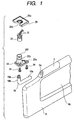
- the sunvisor incorporates a sunvisor body 4 formed into a rectangular-plate-like shape elongated in a lateral direction.
- the sunvisor body 4 is made of, for example, styrofoam.
- a recess 4a for securing a frame 14 formed by combining a vanity mirror 6 and an illuminating light guide 15 formed into a frame shape which surrounds the vanity mirror 6 is formed in the front surface of the sunvisor body 4.
- a visor holder 5 having an insertion hole 5a, into which a stay 16 to be described later is inserted, is joined to the upper portion of the sunvisor body 4.
- the frame 14 is provided with a cover (not shown) which .
- the sunvisor body 4 is covered with an outer skin.
- the L-shape stay 16 has a horizontal shaft portion 16a and a vertical shaft portion 16b.
- the horizontal shaft portion 16a of the stay 16 is inserted into the insertion hole 5a of the visor holder 5 so that the sunvisor body 4 is supported such that vertical movement of the sunvisor body 4 around the horizontal shaft is permitted.
- the stay 16 is locked by a lock spring or the like for the purpose of preventing removal of the stay 16 after the stay 16 has been inserted into the insertion hole 5a of the visor holder 5 to a predetermined depth.
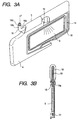
- a translucent (made of, for example, transparent acrylic resin) light guide 17 for the stay 16 is insert-molded into the stay 16.
- Each of an emission end 17a and an incident end 17b of the light guide 17 for the stay 16 is exposed over the end of each of the horizontal shaft portion 16a and the vertical shaft portion 16b.
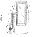
- the emission end 17a of the light guide 17 for the stay 16 at the end of the horizontal shaft portion 16a is made to be opposite to the emission end 19a of the sunvisor-side light guide 19 apart from the emission end 19a for a slight gap.
- the vertical movement of the sunvisor body 4 around the horizontal shaft the vertical movement of the sunvisor body 4 does not encounter any problem.
- the reason for this lies in that the emission end 19a of the sunvisor-side light guide 19 is opposite to the emission end 17a of the light guide 17 for the stay 16 at the end of the horizontal shaft portion 16a apart from the emission end 17a for a slight gap.
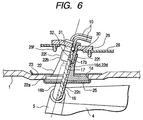
- a stay holder 22 which is joined to the roof panel 1 in the cabin incorporates a flange portion 22a which is made contact with the lower surface of the roof panel 1 and a holder portion 22b which is inserted into the joining hole 1a of the roof panel 1.
- the flange portion 22a is secured to the roof panel 1 with screws 24 by using screw washers 23 (see Fig. 6) made contact with the upper surface of the roof panel 1. Note that the flange portion 22a is covered with a cover 25.
- An insertion hole 22c into which the vertical shaft portion 16b of the stay 16 is inserted rotatively around the vertical shaft, is formed in the lower portion of the holder portion 22b of the stay holder 22.
- An engaging projection 22d for securing an outer groove 16d of the vertical shaft portion 16b when the vertical shaft portion 16b has been inserted to a predetermined depth is formed in the upper portion of the insertion hole 22c.
- the vertical shaft portion 16b is locked so that removal of the vertical shaft portion 16b from the insertion hole 22c is prevented.
- the sunvisor body 4 is supported such that the lateral movement (when the sunvisor is used) of the sunvisor body 4 around the vertical shaft is permitted.
- a sleeve portion 22f is formed in the upper portion of the holder portion 22b of the stay holder 22.
- a lamp socket 31 which accommodates a terminal 30 for the lamp 30 to which an electric wire 10 extended from a battery mounted on the vehicle is connected and an illuminating lamp 32 (see Fig. 7), is joined to a socket holder 29 joined to a car-body member 28 in the roof panel 1.
- the incident end 17b of the light guide 17 for the stay 16 at the end of the vertical shaft portion 16b is made to be opposite to an illuminating lamp 32 of the lamp socket 31 apart from the illuminating lamp 32 for a slight gap while the sleeve portion 22f is being inserted into the lamp socket 31.
- the lateral movement of the sunvisor body 4 does not encounter any problem.
- the reason for this lies in that the illuminating lamp 32 of the lamp socket 31 is made to be opposite to the incident end 17b of the light guide 17 for the stay 16 at the end of the vertical shaft portion 16b apart from the incident end 17b for a slight gap.
- the socket holder 29 has a cylindrical insertion hole portion 29a into which the lamp socket 31 is inserted.
- the insertion hole portion 29a has an outward-opened slit 29b into which the lamp socket 31 is inserted from a direction (from a side position) perpendicular to the axial direction.
- a semi-circular cut portions 29c are formed around the insertion hole portion 29a.
- the cut portions 29c are connected by a plurality of thin bridge portions 29d so that slight displacement of the insertion hole portion 29a in the direction perpendicular to the axial direction is permitted.
- the car-body member 28 has an insertion portion 28a formed by cutting upwards the three sides and by inwardly bending the leading ends of the three sides.
- the socket holder 29 is inserted through one of the portions of the insertion portion 28a (see an arrow A shown in Fig. 9B). Note that the socket holder 29 may be joined to the car-body member 28 with a snap portion 29f, as shown in Fig. 6.
- the lamp socket 31 is not required to be rotated in the insertion hole portion 29a of the socket holder 29. Therefore, the insertion hole portion 29a may be formed into a rectangular shape as a substitute for the cylindrical shape so as to be inserted into a rectangular lamp socket 31 from the axial direction.
- the light guide 17 for the stay 16 is insert-molded into the stay 16.
- the lamp socket 31, which holds the illuminating lamp 32 for emitting illuminating light to the incident end 17b of the light guide 17 for the stay 16, is, in the roof panel 1, disposed to be opposite to the end of the vertical shaft portion 16b of the stay 16.
- the sunvisor body 4 is provided with the sunvisor-side light guide 19 for guiding, to the illuminating light guide 15, illuminating light emitted from the emission end 17a of the light guide 17 for the stay 16 at the end of the horizontal shaft portion 16a of the stay 16.
- illuminating light of the illuminating lamp 32 of the lamp socket 31 in the roof panel 1 is made incident on the incident end 17b of the light guide 17 for the stay 16 at the end of the vertical shaft portion 16b of the stay 16.
- illuminating light emitted from the emission end 17a of the light guide 17 for the stay 16 at the end of the horizontal shaft portion 16a of the stay 16 is guided to the illuminating light guide 15 through the sunvisor-side light guide 19.
- the illuminating light guide 15 illuminates the sunvisor.
- the illuminating light guide 15 is formed into a frame shape which surrounds the vanity mirror 6 joined to the sunvisor body 4, uniform illumination from the outside of the vanity mirror 6 is permitted.
- the operation for inserting the horizontal shaft portion 16a of the stay 16 into the visor holder 5 causes the emission end 17a of the light guide 17 for the stay 16 at the end of the horizontal shaft portion 16a to be opposite to the emission end 19a of the sunvisor-side light guide 19. Therefore, the operation for connecting the connectors required for the conventional technique can be eliminated.
- the operation for joining the stay holder 22 to the roof panel 1 causes the incident end 17b of the light guide 17 for the stay 16 at the end of the vertical shaft portion 16b to be opposite to the socket holder 29 of the lamp socket 31. Therefore, the operation for connecting the connectors which has been required for the conventional technique can be omitted.
- the socket holder 29 into which the lamp socket 31 can be inserted and joined from the direction perpendicular to the axial direction is provided for the car-body member 28. Since the insertion hole portion 29a of the lamp socket 31 is able to be displaced in the direction perpendicular to the axial direction, the lamp socket 31 can be joined to the socket holder 29 of the car-body member 28 by the one-touch operation. Moreover, the lamp socket 31 can be displaced in the direction perpendicular to the axial direction thanks to the insertion hole portion 29a. Therefore, an error or the like from the holder portion 22b of the stay holder 22 which occurs when assembly is performed can be absorbed. Hence it follows that the holder portion 22b of the stay holder 22 can smoothly be inserted.
- the socket holder 29 Since the socket holder 29 is inserted and joined to the insertion portion 28a of the car-body member 28, the socket holder 29 can be joined to the car-body member 28 by the one-touch operation.
- the structure for illuminating a sunvisor according to the present invention is arranged such that the stay-side light guide is insert-molded into the stay.
- the lamp socket is provided for the inside portion of the roof panel.
- the sunvisor-side light guide and the illuminating light guide are provided for the sunvisor body.
- illuminating light of the lamp of the lamp socket is made incident on the incident end of the stay-side light guide.
- Illuminating light emitted from the emission end of the stay-side light guide is guided to the illuminating light guide through the sunvisor-side light guide.
- the sunvisor is illuminated with the illuminating light guide. Therefore, the electric wires of the vanity lamp are not required to pass through the L-shape stay. Thus, the operation for passing the electric wires can be omitted.
- the illuminating light guide is formed in the frame shape which surrounds the vanity mirror of the sunvisor body (aspect 2), illumination from the outside of the vanity mirror is permitted.
- the operation for inserting the horizontal end portion of the stay into the visor holder can simply be completed by making the emission end of the stay-side light guide at the end of the horizontal shaft portion to be opposite to the incident end of the sunvisor-side light guide. Therefore, the operation for connecting the connectors which has been required for the conventional technique can be omitted.
- the operation for joining the stay holder to the roof panel can be completed by simply making the incident end of the stay-side light guide at the end of the vertical shaft portion to be opposite to the lamp of the lamp socket. Therefore, the operation for connecting the connectors which has been required for the conventional technique can be omitted.
- the lamp socket can be joined to the socket holder of the car-body member by the one-touch operation. Moreover, the lamp socket can be displaced in the direction perpendicular to the axial direction by the joining portion. Therefore, an error or the like from the holder portion of the stay holder which occurs when assembly is performed can be absorbed. As a result, the holder portion of the stay holder can smoothly be inserted.
- the socket holder can be joined to the car-body member by the one-touch operation.
Landscapes
- Engineering & Computer Science (AREA)
- Mechanical Engineering (AREA)
- Arrangements Of Lighting Devices For Vehicle Interiors, Mounting And Supporting Thereof, Circuits Therefore (AREA)
- Endoscopes (AREA)
- Non-Portable Lighting Devices Or Systems Thereof (AREA)
- Lighting Device Outwards From Vehicle And Optical Signal (AREA)
Applications Claiming Priority (2)
| Application Number | Priority Date | Filing Date | Title |
|---|---|---|---|
| JP35955298 | 1998-12-17 | ||
| JP35955298A JP3629377B2 (ja) | 1998-12-17 | 1998-12-17 | サンバイザの照明構造 |
Publications (2)
| Publication Number | Publication Date |
|---|---|
| EP1010555A2 true EP1010555A2 (fr) | 2000-06-21 |
| EP1010555A3 EP1010555A3 (fr) | 2002-02-13 |
Family
ID=18465094
Family Applications (1)
| Application Number | Title | Priority Date | Filing Date |
|---|---|---|---|
| EP99117376A Withdrawn EP1010555A3 (fr) | 1998-12-17 | 1999-09-03 | Structure pour éclairer un pare-soleil |
Country Status (3)
| Country | Link |
|---|---|
| US (1) | US6270240B1 (fr) |
| EP (1) | EP1010555A3 (fr) |
| JP (1) | JP3629377B2 (fr) |
Cited By (1)
| Publication number | Priority date | Publication date | Assignee | Title |
|---|---|---|---|---|
| WO2016186911A1 (fr) * | 2015-05-19 | 2016-11-24 | Illinois Tool Works Inc. | Guide de lumière à couverture de lumière améliorée |
Families Citing this family (32)
| Publication number | Priority date | Publication date | Assignee | Title |
|---|---|---|---|---|
| US6368114B1 (en) * | 1998-12-17 | 2002-04-09 | Autonetworks Technologies, Ltd. | Electrical wiring structure for sunvisor |
| CN1240572C (zh) * | 2001-11-27 | 2006-02-08 | 三菱自动车工业株式会社 | 连接器保持结构 |
| TW200424983A (en) * | 2003-05-13 | 2004-11-16 | Benq Corp | Display apparatus |
| ATE320943T1 (de) * | 2003-11-11 | 2006-04-15 | Antolin Grupo Ing Sa | Sicherheitshalterung für einen innenspiegel eines fahrzeugs |
| US20060198123A1 (en) * | 2005-03-01 | 2006-09-07 | Bodgan Radu | Automotive visor with illuminated mirror assembly |
| US7419206B2 (en) * | 2006-07-28 | 2008-09-02 | Newfrey Llc | Interior trim fastener system |
| KR100971692B1 (ko) | 2008-10-16 | 2010-07-22 | 주식회사 용산 | 선바이저용 스위치 |
| US9122320B1 (en) * | 2010-02-16 | 2015-09-01 | VisionQuest Imaging, Inc. | Methods and apparatus for user selectable digital mirror |
| US8425094B2 (en) * | 2010-06-09 | 2013-04-23 | Ford Global Technologies, Llc | Vehicle vanity and light assembly and visor having vanity and dome lighting |
| CA2807615C (fr) | 2012-03-08 | 2020-06-30 | Simplehuman, Llc | Miroir de meuble-coiffeuse |
| USD737060S1 (en) | 2013-08-22 | 2015-08-25 | Simplehuman, Llc | Vanity mirror |
| USD751829S1 (en) | 2014-03-13 | 2016-03-22 | Simplehuman, Llc | Vanity mirror |
| US10076176B2 (en) | 2015-03-06 | 2018-09-18 | Simplehuman, Llc | Vanity mirror comprising light sources and methods of manufacture thereof |
| USD785345S1 (en) | 2015-03-06 | 2017-05-02 | Simplehuman, Llc | Mirror |
| CN106364289B (zh) | 2015-07-20 | 2021-05-18 | 福特环球技术公司 | 车辆遮阳板支架及遮阳板总成 |
| KR200484557Y1 (ko) * | 2016-01-25 | 2017-09-22 | 주식회사 세코닉스 | 무드조명이 구비된 차량용 선바이저 |
| US20170240103A1 (en) | 2016-02-23 | 2017-08-24 | Motus Integrated Technologies | Vehicle sun visor assembly having an electrical system |
| KR101807074B1 (ko) * | 2016-05-26 | 2017-12-08 | 현대자동차 주식회사 | 차량의 선바이저용 라이트 가이드 장치 |
| DE202017006809U1 (de) * | 2016-11-03 | 2018-07-26 | Basf Se | Tageslichtelement |
| US10869537B2 (en) | 2017-03-17 | 2020-12-22 | Simplehuman, Llc | Vanity mirror |
| USD816350S1 (en) | 2017-03-17 | 2018-05-01 | Simplehuman, Llc | Vanity mirror |
| USD848158S1 (en) | 2017-12-28 | 2019-05-14 | Simplehuman, Llc | Vanity mirror |
| US11026497B2 (en) | 2018-02-14 | 2021-06-08 | Simplehuman, Llc | Compact mirror |
| USD846288S1 (en) | 2018-03-08 | 2019-04-23 | Simplehuman, Llc | Vanity mirror |
| US11708031B2 (en) | 2018-03-22 | 2023-07-25 | Simplehuman, Llc | Voice-activated vanity mirror |
| JP6778720B2 (ja) * | 2018-08-02 | 2020-11-04 | 矢崎総業株式会社 | サンバイザ用コネクタ |
| USD874161S1 (en) | 2018-09-07 | 2020-02-04 | Simplehuman, Llc | Vanity mirror |
| CA3113402A1 (fr) | 2018-09-19 | 2020-03-26 | Simplehuman, Llc | Miroir de toilette |
| USD925928S1 (en) | 2019-03-01 | 2021-07-27 | Simplehuman, Llc | Vanity mirror |
| US11640042B2 (en) | 2019-03-01 | 2023-05-02 | Simplehuman, Llc | Vanity mirror |
| USD927863S1 (en) | 2019-05-02 | 2021-08-17 | Simplehuman, Llc | Vanity mirror cover |
| CA3230834A1 (en) | 2023-03-03 | 2025-06-27 | Simplehuman, Llc | Vanity mirror with hidden sensor |
Family Cites Families (9)
| Publication number | Priority date | Publication date | Assignee | Title |
|---|---|---|---|---|
| DE2703447C3 (de) * | 1977-01-28 | 1979-09-06 | Gebr. Happich Gmbh, 5600 Wuppertal | Sonnenblende für Fahrzeuge |
| US4792884A (en) * | 1987-10-19 | 1988-12-20 | Prince Corporation | Illuminated vanity mirror visor |
| DE3916560A1 (de) * | 1989-05-20 | 1990-11-22 | Zipperle Eugen Gmbh & Co Kg | Sonnenblende fuer kraftfahrzeuge |
| FR2659596B1 (fr) * | 1990-03-13 | 1992-12-11 | Rockwell Abs France | Bras de support coude pour pare-soleil alimente electriquement par des conducteurs. |
| US5303125A (en) * | 1993-04-19 | 1994-04-12 | Miller Jack V | Fiber optic aimable spotlight luminaire |
| DE4328890C1 (de) * | 1993-08-27 | 1994-12-22 | Happich Gmbh Gebr | Sonnenblende für Fahrzeuge |
| DE4337808A1 (de) * | 1993-11-05 | 1995-05-11 | Happich Gmbh Gebr | Sonnenblende für Fahrzeuge |
| US5452186A (en) * | 1994-03-30 | 1995-09-19 | Ford Motor Company | Light distribution system |
| US5548492A (en) * | 1995-04-12 | 1996-08-20 | Prince Corporation | Slide-out fiber-optic illuminated vanity mirror |
-
1998
- 1998-12-17 JP JP35955298A patent/JP3629377B2/ja not_active Expired - Fee Related
-
1999
- 1999-08-31 US US09/386,340 patent/US6270240B1/en not_active Expired - Fee Related
- 1999-09-03 EP EP99117376A patent/EP1010555A3/fr not_active Withdrawn
Non-Patent Citations (1)
| Title |
|---|
| None |
Cited By (2)
| Publication number | Priority date | Publication date | Assignee | Title |
|---|---|---|---|---|
| WO2016186911A1 (fr) * | 2015-05-19 | 2016-11-24 | Illinois Tool Works Inc. | Guide de lumière à couverture de lumière améliorée |
| US10286841B2 (en) | 2015-05-19 | 2019-05-14 | Illinois Tool Works Inc. | Light guide with opaque light cover applied by injection molding |
Also Published As
| Publication number | Publication date |
|---|---|
| JP2000177388A (ja) | 2000-06-27 |
| EP1010555A3 (fr) | 2002-02-13 |
| JP3629377B2 (ja) | 2005-03-16 |
| US6270240B1 (en) | 2001-08-07 |
Similar Documents
| Publication | Publication Date | Title |
|---|---|---|
| US6270240B1 (en) | Structure for illuminating sunvisor | |
| US4491899A (en) | Visor cover assembly | |
| US6899449B2 (en) | Lamp unit assembling method and lamp unit mounting structure | |
| EP1010556A2 (fr) | Structure de câblage pour pare-soleil | |
| US6139083A (en) | Sliding core visor | |
| US5533776A (en) | Sun visor for motor vehicles | |
| JP2924553B2 (ja) | 電気自動車における充電用コネクタ | |
| US5022699A (en) | Covered illuminated vanity mirror | |
| US5120914A (en) | Steering column switch for motor vehicles | |
| JP2006506275A (ja) | カバー付き照明付きバニティミラー組立体 | |
| JP4908673B2 (ja) | ルームミラー | |
| US6129446A (en) | Inside light | |
| US7178956B2 (en) | Interior illumination lamp | |
| JPH08250248A (ja) | 電球ソケット | |
| CA2260780A1 (fr) | Commutateur multiple pour automobile | |
| JPH079848A (ja) | 車両用サンバイザ | |
| WO2013111580A1 (fr) | Douille d'ampoule et système d'éclairage | |
| JPS63232021A (ja) | ランプ付バニテイミラ− | |
| CN114750576B (zh) | 带化妆镜的遮阳板 | |
| KR200415898Y1 (ko) | 차량용 램프에 사용되는 벌브홀더와 커넥터 조립구조 | |
| US4910648A (en) | Illuminated visor mounting bracket | |
| JP3388611B2 (ja) | 電気機器用構造体のためのランプ保持体 | |
| JP2566990Y2 (ja) | 電球ソケット | |
| JPS6230241Y2 (fr) | ||
| CN1030479C (zh) | 插座式袖珍显微镜 |
Legal Events
| Date | Code | Title | Description |
|---|---|---|---|
| PUAI | Public reference made under article 153(3) epc to a published international application that has entered the european phase |
Free format text: ORIGINAL CODE: 0009012 |
|
| AK | Designated contracting states |
Kind code of ref document: A2 Designated state(s): AT BE CH CY DE DK ES FI FR GB GR IE IT LI LU MC NL PT SE |
|
| AX | Request for extension of the european patent |
Free format text: AL;LT;LV;MK;RO;SI |
|
| PUAL | Search report despatched |
Free format text: ORIGINAL CODE: 0009013 |
|
| AK | Designated contracting states |
Kind code of ref document: A3 Designated state(s): AT BE CH CY DE DK ES FI FR GB GR IE IT LI LU MC NL PT SE |
|
| AX | Request for extension of the european patent |
Free format text: AL;LT;LV;MK;RO;SI |
|
| RIC1 | Information provided on ipc code assigned before grant |
Free format text: 7B 60J 3/00 A, 7B 60J 3/02 B, 7B 60Q 3/02 B |
|
| AKX | Designation fees paid | ||
| REG | Reference to a national code |
Ref country code: DE Ref legal event code: 8566 |
|
| RAP1 | Party data changed (applicant data changed or rights of an application transferred) |
Owner name: SUMITOMO ELECTRIC INDUSTRIES, LTD. Owner name: SUMITOMO WIRING SYSTEMS, LTD. Owner name: AUTONETWORKS TECHNOLOGIES, LTD. |
|
| STAA | Information on the status of an ep patent application or granted ep patent |
Free format text: STATUS: THE APPLICATION IS DEEMED TO BE WITHDRAWN |
|
| 18D | Application deemed to be withdrawn |
Effective date: 20020214 |