EP1010660A1 - Windevorrichtung für aufzug - Google Patents
Windevorrichtung für aufzug Download PDFInfo
- Publication number
- EP1010660A1 EP1010660A1 EP97954869A EP97954869A EP1010660A1 EP 1010660 A1 EP1010660 A1 EP 1010660A1 EP 97954869 A EP97954869 A EP 97954869A EP 97954869 A EP97954869 A EP 97954869A EP 1010660 A1 EP1010660 A1 EP 1010660A1
- Authority
- EP
- European Patent Office
- Prior art keywords
- magnetic pole
- detector
- drive
- rotation
- field
- Prior art date
- Legal status (The legal status is an assumption and is not a legal conclusion. Google has not performed a legal analysis and makes no representation as to the accuracy of the status listed.)
- Granted
Links
Images


Classifications
-
- H—ELECTRICITY
- H02—GENERATION; CONVERSION OR DISTRIBUTION OF ELECTRIC POWER
- H02K—DYNAMO-ELECTRIC MACHINES
- H02K29/00—Motors or generators having non-mechanical commutating devices, e.g. discharge tubes or semiconductor devices
- H02K29/06—Motors or generators having non-mechanical commutating devices, e.g. discharge tubes or semiconductor devices with position sensing devices
- H02K29/08—Motors or generators having non-mechanical commutating devices, e.g. discharge tubes or semiconductor devices with position sensing devices using magnetic effect devices, e.g. Hall-plates, magneto-resistors
-
- B—PERFORMING OPERATIONS; TRANSPORTING
- B66—HOISTING; LIFTING; HAULING
- B66B—ELEVATORS; ESCALATORS OR MOVING WALKWAYS
- B66B1/00—Control systems of elevators in general
- B66B1/34—Details, e.g. call counting devices, data transmission from car to control system, devices giving information to the control system
- B66B1/3492—Position or motion detectors or driving means for the detector
-
- B—PERFORMING OPERATIONS; TRANSPORTING
- B66—HOISTING; LIFTING; HAULING
- B66B—ELEVATORS; ESCALATORS OR MOVING WALKWAYS
- B66B11/00—Main component parts of lifts in, or associated with, buildings or other structures
- B66B11/04—Driving gear ; Details thereof, e.g. seals
- B66B11/08—Driving gear ; Details thereof, e.g. seals with hoisting rope or cable operated by frictional engagement with a winding drum or sheave
-
- H—ELECTRICITY
- H02—GENERATION; CONVERSION OR DISTRIBUTION OF ELECTRIC POWER
- H02K—DYNAMO-ELECTRIC MACHINES
- H02K7/00—Arrangements for handling mechanical energy structurally associated with dynamo-electric machines, e.g. structural association with mechanical driving motors or auxiliary dynamo-electric machines
- H02K7/10—Structural association with clutches, brakes, gears, pulleys or mechanical starters
- H02K7/1004—Structural association with clutches, brakes, gears, pulleys or mechanical starters with pulleys
- H02K7/1012—Machine arranged inside the pulley
- H02K7/1016—Machine of the outer rotor type
-
- H—ELECTRICITY
- H02—GENERATION; CONVERSION OR DISTRIBUTION OF ELECTRIC POWER
- H02K—DYNAMO-ELECTRIC MACHINES
- H02K7/00—Arrangements for handling mechanical energy structurally associated with dynamo-electric machines, e.g. structural association with mechanical driving motors or auxiliary dynamo-electric machines
- H02K7/14—Structural association with mechanical loads, e.g. with hand-held machine tools or fans
Definitions
- the present invention relates to an elevator apparatus, and more particularly to a drive machine for elevators which employs an outer rotor motor.
- Figs. 11 and 12 show a conventional elevator apparatus disclosed in, for example, Japanese Unexamined Patent Publication No. 7-117957.
- the disclosed elevator apparatus is of the traction sheave type wherein a main cable is wound over a drive sheave, and a cage and a counterweight are moved up and down in opposite directions.
- the elevator apparatus employs, as a winder, an outer rotor motor.
- Fig. 11 is a perspective view of the elevator apparatus
- Fig. 12 is an enlarged sectional view of a drive machine shown in Fig. 11.
- Figs. 11 and 12 denoted by numeral 1 is an elevator pit
- 2 is a cage
- 3 is a cage guide rail vertically provided in pair within the elevator pit 1 for guiding both sides of the cage 2 so that the cage moves up and down along a predetermined path
- 4 is a counterweight
- 5 is a counterweight guide rail vertically provided in pair within the elevator pit 1 for guiding both sides of the counterweight 4 so that the counterweight moves up and down along a predetermined path
- 6 is a braking device associated with the counterweight 4 and tightly pressed against the counterweight guide rails 5 for applying a brake as the occasion requires.
- Numeral 7 denotes a support beam provided at the top of the elevator pit 1
- 8 denotes a winder comprising an outer rotor motor provided at the top of the elevator pit 1.
- the winder 8 mainly comprises a stationary shaft 9 having opposite ends supported by and fixed to the support beams 7, an armature iron-core 11 fixed to the shaft 9 and having armature coils 10 wound over the same, and a rotor 12 rotatably supported by the shaft 9 and constituting a drive sheave.
- the rotor 12 includes a field iron-core 13, a field permanent magnet 14, a drive sheave 16 having cable grooves formed in its outer periphery, and bearings 17 disposed between the rotor and the shaft 9 for rotatably supporting the former relative to the latter.
- Numeral 18 denotes an elevator main cable wound along the sheave groove 15, the main cable having one end coupled to the cage 2 and the other end coupled to the counterweight 4.
- Numeral 19 denotes a braking device associated with the rotor 12 for stopping the rotor 12.
- Numeral 20 denotes an absolute value encoder in the form of a ring.
- the absolute value encoder 20 is arranged such that it surrounds a projected flange of the rotor 12, is joined to the projected flange of the rotor 12 through a baring 21 for free rotation of the rotor 12, and is fixed through a mounting fixture 23 to an encoder holder 22 which is secured to the shaft 9.
- Numeral 24 denotes a supporting fixture provided on each of the support beams 7 on both sides for supporting the shaft 9.
- the magnetic pole position of the field permanent magnet 14 is detected by the absolute value encoder 20, and the phases of currents supplied to the armature coils 10 are controlled in accordance with the detected result. Also, the rotating speed and the rotating direction of the rotor 12 and hence the drive sheave 16 are detected by the absolute value encoder 20 in order to control the rising/lowering speed and the moving direction of the cage 2.
- the absolute value encoder 20 is in the ring form and arranged in a surrounding relation to the projected flange of the rotor 12, its inner diameter is so large that an inexpensive absolute value encoder, which is usually employed in general motors having rotary shafts, is not usable. This raises another problem that the absolute value encoder 20 must be a custom and expensive product.
- Still another problem is that because the magnetic pole position of the field magnet is indirectly determined by the absolute value encoder 20 surrounding the projected flange of the rotor 12, the accurate magnetic pole position of the field magnet cannot be obtained.
- the present invention has been accomplished with the view of solving the-problems set forth above, and its object is to provide a drive machine for elevators which can determine the accurate magnetic pole position of a field magnet, and can facilitate maintenance work for a detecting unit to detect the magnetic pole position, the rotating speed and the rotating direction of the field magnet.
- a first aspect of the present invention resides in a drive machine for elevators, which comprises a rotatable drive sheave over which a main cable for hanging an elevator cage is wound, a stationary shaft for supporting rotation of the drive sheave and bearing a load applied to the drive sheave from the main cable, a field magnet attached to the drive sheave, constituting a part of an electric motor, and comprising at least one pair of magnetic poles, an armature attached to the stationary shaft in a facing relation to the field magnet and constituting another part of the motor, and a field magnetic pole detector for detecting the predetermined magnetic pole of the field magnet rotated together with the drive sheave.
- a second aspect of the present invention resides in, on the basis of the drive machine for elevators according to the first aspect, that the field magnet comprises a permanent magnet.
- a third aspect of the present invention resides in, on the basis of the drive machine for elevators according to the first or second aspect, that the field magnetic pole detector comprises a magnetic sensor attached to the stationary side in a close and facing relation to the field magnet.
- a fourth aspect of the present invention resides in, on the basis of the drive machine for elevators according to the first aspect, that a detected portion indicating the position of the magnetic pole disposed on the drive sheave is provided on the drive sheave in a facing relation to the field magnetic pole detector, and the position of the predetermined magnetic pole is recognized with the field magnetic pole detector detecting the detected portion.
- a fifth aspect of the present invention resides in, on the basis of the drive machine for elevators according to the fourth aspect, that the detected portion comprises a convex or concave portion formed on or in the surface of the drive sheave corresponding to the position of the predetermined magnetic pole.
- a sixth aspect of the present invention resides in, on the basis of the drive machine for elevators according to the first aspect, that the field magnetic pole detector is provided at least three at a pitch equal to 1/3 of the pitch of one pair of the field magnetic poles.
- a seventh aspect of the present invention resides in, on the basis of the drive machine for elevators according to the second or sixth aspect, further comprising a rotation detector for detecting rotation of the drive sheave with respect to the stationary shaft as a reference, and drive control means for executing drive control of the motor in accordance with results detected by the rotation detector and the field magnetic pole detector, wherein the drive control means starts up the motor in accordance with an imaginary field magnetic pole position when the magnetic pole position of the field magnet attached to the drive sheave is not known at the start-up of the elevator, and executes the drive control in accordance with the results detected by the field magnetic pole detector and the rotation detector after the field magnetic pole position has been recognized upon operation of the field magnetic pole detector.
- An eighth aspect of the present invention resides in, on the basis of the drive machine for elevators according to the first aspect, further comprising a rotation detector for detecting rotation of the drive sheave with respect to the stationary shaft as a reference, detection difference calculating means for detecting the difference between the rotation of the drive sheave detected by the rotation detector and the rotation of the drive sheave detected by the field magnetic pole detector, and anomaly determining means for determining the occurrence of an anomaly when a value of the difference determined by the detection difference calculating means exceeds a predetermined value.
- a ninth aspect of the present invention resides in, on the basis of the drive machine for elevators according to the eighth aspect, further comprising drive control means for executing drive control of the motor in accordance with results detected by the rotation detector and the field magnetic pole detector, wherein when the value of the difference determined by the detection difference calculating means does not exceed the predetermined value, the drive control means executes the control while correcting an output value of the rotation detector in accordance with the value of the difference.
- a tenth aspect of the present invention resides in, on the basis of the drive machine for elevators according to the first aspect, further comprising a rotation detector for detecting rotation of the drive sheave with respect to the stationary shaft as a reference, memory means for storing an output of the rotation detector in a corresponding relation to the position detected by the field magnetic pole detector while the field magnetic pole detector is detecting the field magnetic pole position with the rotation of the drive sheave, and drive control means for executing drive control of the motor in accordance with results detected by the rotation detector and the field magnetic pole detector, wherein the drive control means utilizes values stored in the memory means for phase control of electric power supplied to the armature.
- An eleventh aspect of the present invention resides in, on the basis of the drive machine for elevators according to the first aspect, further comprising a rotation detector for detecting rotation of the drive sheave with respect to the stationary shaft as a reference, and drive control means for executing drive control of the motor in accordance with results detected by the rotation detector and the field magnetic pole detector, wherein the amount of change in value detected by the rotation detector is determined at the start-up of the elevator while the field magnetic pole detector detects one pair of the field magnetic poles, and the drive control means executes phase control of the motor by setting the amount of change as a reference value of a phase signal for one pair of the field magnetic poles since then.
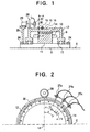
- Fig. 1 is a sectional view showing a structure of a drive machine for elevators according to one embodiment of the present invention.
- Fig. 1 the same or corresponding parts as or to those in the conventional drive machine described above are denoted by the same symbols.
- a winder 8 mainly comprises a stationary shaft 9 having opposite ends supported by supporting fixtures 24, an armature iron-core 11 (armature) having armature coils 10 wound over the same, and a rotor 12 rotatably supported by the shaft 9 and constituting a drive sheave 16.
- armature armature
- rotor 12 rotatably supported by the shaft 9 and constituting a drive sheave 16.
- O denotes an axis of the shaft 9.
- the rotor 12 includes a field permanent magnet 14 (field magnet) disposed inside the rotor to face the armature iron-core 11, cable grooves 15 formed in an outer periphery of the rotor for receiving a main cable 18 wound over the rotor, and machined portions 30 (detected portions) in the form of recesses which are used to detect the magnetic pole position of the field permanent magnet 14. Additionally, bearings 17 are disposed between the rotor 12 and the shaft 9.
- field permanent magnet 14 field magnet
- cable grooves 15 formed in an outer periphery of the rotor for receiving a main cable 18 wound over the rotor
- machined portions 30 detected portions in the form of recesses which are used to detect the magnetic pole position of the field permanent magnet 14.
- bearings 17 are disposed between the rotor 12 and the shaft 9.
- the present invention is also similarly applicable to another type of winder wherein an iron core having coils wound around the same is disposed (not shown) in place of the permanent magnet, and electric power is supplied to the coils through a slip ring, thereby generating a magnetic field as with the permanent magnet.
- proximity switches 27 as field magnetic pole detectors for detecting the position of each machined portion 30 in the form of a recess, and a rotary encoder 29 serving as a rotation detector and including a roller 28 held pressed against the outer periphery of the rotor 12 for detecting the rotating speed and the rotating direction of the rotor 12.
- Numeral 25 denotes a mounting stand for the rotary encoder 29.
- the proximity switches 27 may be attached to the mounting stand 25, or may be attached to a dedicated mounting stand (not shown) which is provided separately.
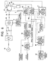
- Fig. 2 is a sectional view taken along the line A - A of Fig. 1, showing the positional relationship among the machined portion 30 in the form of a recess, the field permanent magnet 14, and the proximity switches 27a - 27c.
- the outer periphery of the rotor 12 is machined to have a recess (30) in a position coincident with the position of each N pole of the field permanent magnet 14 where the pole is fixed to the rotor 12, as viewed from the center LO of the rotating shaft in the radial direction, while the rotor outer periphery is not machined to have a recess in a position coincident with the position of each S pole where it is fixed to the rotor 12.
- three proximity switches 27a - 27c are mounted in a close relation to the concave and convex machined portions 30. Supposing that an angle occupied by one pair of N and S poles of the field permanent magnet 14 is ⁇ , the proximity switches 27a - 27c are arranged along the outer periphery of the rotor 12 in such positions that the interval (pitch) between the proximity switches is ⁇ /3.
- the signals from the proximity switches 27a - 27c change as shown, namely change in six combinations P1 - P6, while the rotor moves through-the angle ⁇ corresponding to one pair of the concave and convex portions.
- the signals from the proximity switches 27a - 27c change in the same manner repeatedly. Since the concave and convex portions are positioned in a one-to-one relation to the magnetic poles, ⁇ is given by 360 degrees representing one cycle of the magnetic pole phase, and therefore P1 to P6 each represent a range of 60 degrees. In other words, the magnetic pole position can be determined based on the combinations in state of the signals from the proximity switches 27a - 27c with resolution of 60 degrees.
- a synchronous motor of the type employing a permanent magnet cannot start up unless the magnetic pole position of a fertil magnet is known at the time of start-up.
- the magnetic pole position can be detected with an angular range of 60 degrees. Assuming that the magnetic pole position locates at the middle of the 60-degree range, an error between the actual magnetic pole position and the measured magnetic pole position is ⁇ 30 degrees at maximum.
- the magnetic pole position can be precisely detected at that time, and current phase control can be performed with a highly-accurate magnetic pole position signal since then.
- the changing-over point between the concave and convex portions is coincident with the changing-over point between the magnetic poles, this provides such an advantage that the changing-over point between the magnetic poles can be directly read based on the signals from the proximity switches 27a - 27c.
- the rotating direction and the rotating speed of the rotor 12 are determined based on a signal from the rotary encoder 29.
- the concave and convex machined portions may be provided in any other suitable locations than the outer periphery of the rotor.
- a similar operating effect as described above can be obtained if the concave and convex machined portions are located in coincidence with the positions of the magnetic poles of the field magnet as viewed from the center of the rotating shaft in the radial direction.
- the similar operating effect can also be obtained by attaching a ring with concave and convex portions in coincidence with the magnetic pole positions rather than directly machining the rotor (drive sheave) to have the concave and convex portions.
- the proximity switches 27a - 27c serving as field magnetic pole detectors and the rotary encoder 29 serving as a rotation detector are arranged as separate components in an easily detachable manner, it is easy to carry out check and displacement in the event of failure.
- the winder can be controlled with good accuracy.
- Fig. 4 is a sectional view showing a structure of a drive machine for elevators according to another embodiment of the present invention
- Fig. 5 is a sectional view taken along the line B - B of Fig. 4.
- This embodiment employs, as field magnetic pole detectors, three magnetic sensors 70a - 70c provided in the proximity of the field permanent magnet 14.
- Numeral 71 denotes a mounting fixture for the magnetic sensors 70a - 70c.
- the magnetic sensors 70a - 70c obtain information about the position in a field magnet, i.e., the field magnetic pole position, by directly detecting the magnetic field generated by the field permanent magnet 14.
- the construction is simplified and the magnetic pole position can be more precisely obtained.
- the position in the field magnet can be roughly detected from the magnitude of detected magnetic flux even while the rotor is stopped.
- FIG. 6 is a control block diagram of an inverter for driving the winder 8 which comprises a synchronous motor of the outer rotor type employing a permanent magnet as a field magnet. Note that an elevator control section, a position control section, etc., which are not directly related to the present invention, are omitted from the drawing.
- Numeral 43 denotes an inverter for driving the winder 8 which comprises an outer rotor motor
- 27 denotes a proximity switch for detecting the field magnetic pole position within the winder 8
- 29 denotes a rotary encoder for detecting the rotation of the winder 8 through the roller 28.
- 40 is a power supply
- 41 is a converter
- 42 is a smoothing capacitor
- 2 is an elevator cage
- 4 is a counterweight.
- Numeral 45 denotes a speed detecting section for determining the speed based on a signal from the rotary encoder 29, 46 denotes a phase detecting section for determining the current phase based on a signal from the rotary encoder 29, 47 denotes a magnetic pole position detecting section for determining the magnetic pole position based on signals from the proximity switches 27, 49 denotes a speed control section for combining a speed command and a speed feedback signal ⁇ to calculate a torque current command iq , 50 denotes a current command creating section for calculating a current command from an excitation current command id , the torque current command iq and a phase signal ⁇ , and 51 denotes a current control section for combining the current command and a current detection signal from a current sensor 44 to output a control signal to the inverter 43.
- Numeral 55 denotes memory means for storing, in a correlated manner, the current phase, i.e., the position in the field magnet, determined by the phase detecting section 46 based on the signal from the rotary encoder 29, and the magnetic pole position recognized by the magnetic pole position detecting section 47 based on the signals detected by the proximity switches 27.
- Numeral 56 denotes detection difference calculating means for determining the difference between the magnetic pole position recognized by the magnetic pole position detecting section 47 based on the signals detected by the proximity switches 27 and the magnetic pole position determined by the phase detecting section 46 based on the signal from the rotary encoder 29.
- Numeral 57 denotes anomaly determining means for generating an abnormal signal upon determining the occurrence of an anomaly if the difference or deviation in the magnetic pole position resulted from the different detectors and determined by the detection difference calculating means 56 exceeds a predetermined value.
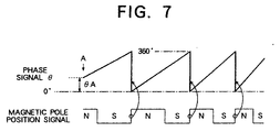
- phase signal ⁇ is set to a phase signal ⁇ A that is determined from a combination of the signals from the three proximity switches 27 in accordance with the above-described method.
- the phase detecting section 46 counts the number of the pulses, and outputs the phase signal ⁇ after multiplying the counted number by a phase angle corresponding to one pulse.
- the current phase signal ⁇ must be coincident with the cycle of the magnetic pole position of the field magnet.
- phase signal ⁇ is reset to be coincident with 0 degree, for example, at the changing-over point from the S to N pole of the magnetic pole position signal determined based on the signals from the proximity switches 27, as shown in Fig. 7.
- the length of one cycle of each detector signal may change due to errors in machining of the concave machined portions 30 serving as the detected portions in Embodiment 1, or errors in installation of the proximity switches 27a - 27c used in Embodiment 1 and the magnetic sensors 70a - 70c used in Embodiment 2 which serves as the field magnetic pole detectors. If the length of one cycle is shortened, for example, the phase signal ⁇ is reset to 0 degree before reaching 360 degrees. Conversely, if the length of one cycle is prolonged, the phase signal ⁇ is reset midway the succeeding cycle. This results in that the phase signal ⁇ becomes not consistent and the motor cannot rotate smoothly.
- a time period (a) in Fig. 8 is represented by a value of C2 - C1, a time period (b) by a value of C3 - C2, and a time period (c) by a value of C4 - C3.
- the amount of change in value of the phase signal ⁇ corresponding to one count of the output pulses from the rotation detector is calculated from the stored pulse counted values, and is set to be larger than in the standard time period to modify the value of the phase signal ⁇ so that one cycle completes at 360 degrees.
- the amount of change in value of the phase signal ⁇ is set to be smaller than in the standard time period to modify the value of the phase signal ⁇ so that one cycle completes at 360 degrees. Stated otherwise, as shown in Fig.
- phase signal ⁇ has the same slope for each time period in the unmodified case, the slope of the phase signal ⁇ is changed depending on the stored length of one cycle in the modified case. With such a modification, the value of the phase signal ⁇ is kept from becoming inconsistent, and smooth phase control can be achieved.
- the magnetic pole position detecting section 47 detects the changing-over point in the cycle of the magnetic poles, and assigns the successive number to each cycle from the first cycle over a full turn. At the same time, the assigned numbers and the difference in counted value of the output pulses from the rotary encoder 29 for each cycle are stored in the storage means 55. After that, the magnetic pole position detecting section 47 outputs, to the phase detecting section 46, information indicating in what number of magnetic pole cycle the winder 8 is positioned at this moment.
- the phase detecting section 46 reads the difference in counted value of the corresponding magnetic pole cycle from the storage means 55, and determines the length of the cycle. Then, in consideration of correspondence between the signal newly inputted from the rotary encoder 29 and the length of the cycle, the phase detecting section 46 modifies and calculates the phase signal ⁇ so that one cycle completes at 360 degrees. The modified phase signal ⁇ is outputted to the current command creating section 50.
- the detection difference calculating means 56 determines how far the phase signal ⁇ from the phase detecting section 46 deviates from 0 degree or 360 degrees.
- the anomaly determining means 57 sets an angle of a certain width d at the changing-over point from the S to N pole of the magnetic pole position signal from the magnetic pole position detecting section 47 as shown in Fig. 9, and monitors whether the angle of the phase signal ⁇ from the phase detecting section 46 deviates over the angle d not, thereby outputting an abnormal signal if the deviation over the angle d occurs.
- the width of d is set to about 10 degrees in terms of phase angle, taking into account that a torque reduction should not be so increased and that a speed detection error should not be so enlarged.
- the roller 28 may be abraded to cause a change of configuration over time and hence to produce an error in the phase signal ⁇ .
- the roller 28 has a diameter of 100 mm and the length of one pair of magnetic poles of the field permanent magnet 14 is exactly equal to 1/2 of the outer circumference of the roller 28, if the roller 28 is abraded 0.1 mm and the diameter is changed to 99.8 mm, the phase signal ⁇ would shift 90 degrees in terms of the magnetic pole phase after only 62.5 rotations of the roller 28.
- the 90-degree shift of the magnetic pole phase means that the torque applied to the winder 8 becomes zero.
- the number of output pulses from the rotary encoder 29 is counted (a value given by PB - PA in the drawing) for one cycle of the signal from the proximity switch 27 (indicated by the signal from 27a in the drawing), and the counted value is used as a reference value for one cycle of the magnetic pole phase in the subsequent phase calculation until the winder 8 is stopped. Since the length of one pair of magnetic poles of the field permanent magnet 14 is fixed regardless of the roller abrasion, the pulse count for one cycle of the magnetic pole phase can be correctly detected even if the roller diameter varies due to a change of configuration over time.
- a drive machine for elevators comprises a rotatable drive sheave over which a main cable for hanging an elevator cage is wound, a stationary shaft for supporting rotation of the drive sheave and bearing a load applied to the drive sheave from the main cable, a field magnet attached to the drive sheave, constituting a part of an electric motor, and comprising at least one pair of magnetic poles, an armature attached to the stationary shaft in a facing relation to the field magnet and constituting another part of the motor, and a field magnetic pole detector for detecting the predetermined magnetic pole of the field magnet rotated together with the drive sheave.
- the field magnetic pole detector capable of directly and precisely detecting the position in the field magnet, rotational angle control of the drive sheave and control of the motor can be implemented with good accuracy.
- the field magnet comprises a permanent magnet. If a field magnet using winding coils is attached to the rotatable drive sheave, a special device such as a slip ring is required to supply excitation currents to the coils. By contrast, the use of a permanent magnet eliminates the need of such a special device.
- the field magnetic pole detector comprises a magnetic sensor attached to the stationary side in a close and facing relation to the field magnet. Therefore, the magnetism generated by the field magnet can be directly detected by the magnetic sensor, and hence the construction is simplified. In addition, by combining the magnetic sensor with the use of the above permanent magnet, the position in the field magnetic can be roughly detected from the magnitude of detected magnetic flux even while the motor is stopped.
- a detected portion indicating the position of the magnetic pole disposed on the drive sheave is provided on the drive sheave in a facing relation to the field magnetic pole detector, and the position of the predetermined magnetic pole is recognized with the field magnetic pole detector detecting the detected portion.
- the detected portion comprises a convex or concave portion formed on or in the surface of the drive sheave corresponding to the position of the predetermined magnetic pole.
- the field magnetic pole detector is provided at least three at a pitch equal to 1/3 of the pitch of one pair of the field magnetic poles. Therefore, the field magnetic pole position can be recognized with resolution of 60 degrees by only the field magnetic pole detectors. In other words, the field magnetic pole position can be detected by a small number of field magnetic pole detectors. In addition, even the resolution of 60 degrees corresponds to a torque error less than 15 % in control of the motor, and is within the allowable range from the viewpoint of control capability.
- the drive machine for elevators further comprises a rotation detector for detecting rotation of the drive sheave with respect to the stationary shaft as a reference, and drive control means for executing drive control of the motor in accordance with results detected by the rotation detector and the field magnetic pole detector, wherein the drive control means starts up the motor in accordance with an imaginary field magnetic pole position when the magnetic pole position of the field magnet attached to the drive sheave is not known at the start-up of the elevator, and executes the drive control in accordance with the results detected by the field magnetic pole detector and the rotation detector after the field magnetic pole position has been recognized upon operation of the field magnetic pole detector.
- the drive control means cannot know in which position the motor locates relative to the corresponding field magnetic pole at the start-up, i.e., when it is not known how far the motor has rotated, before stopping, from the point to be detected (the changing-over point of the field magnetic pole), the imaginary field magnetic pole position is introduced and phase control is performed in accordance with the imaginary field magnetic pole position until the first field magnetic pole detector starts operation.
- the drive sheave can be started up even if the position in the field magnet is not known at the start-up.
- the drive machine for elevators further comprises a rotation detector for detecting rotation of the drive sheave with respect to the stationary shaft as a reference, detection difference calculating means for detecting the difference between the rotation of the drive sheave detected by the rotation detector and the rotation of the drive sheave detected by the field magnetic pole detector, and anomaly determining means for determining the occurrence of an anomaly when a value of the difference determined by the detection difference calculating means exceeds a predetermined value. It is therefore possible to early find an anomaly in the rotation detector, the field magnetic pole detector, or the detected portion.
- the drive machine for elevators further comprises drive control means for executing drive control of the motor in accordance with results detected by the rotation detector and the field magnetic pole detector, wherein when the value of the difference determined by the detection difference calculating means does not exceed the predetermined value, the drive control means executes the control while correcting an output value of the rotation detector in accordance with the value of the difference. Accordingly, if there occurs a slight anomaly such as abrasion of a roller over time, the elevator can continue the operation for the present just by slightly correcting a detected value of the rotation detector. As a result, a rest time of the elevator attributable to the detection of anomaly can be minimized.
- the drive machine for elevators further comprises a rotation detector for detecting rotation of the drive sheave with respect to the stationary shaft as a reference, memory means for storing an output of the rotation detector in a corresponding relation to the position detected by the field magnetic pole detector while the field magnetic pole detector is detecting the field magnetic pole position with the rotation of the drive sheave, and drive control means for executing drive control of the motor in accordance with results detected by the rotation detector and the field magnetic pole detector, wherein the drive control means utilizes values stored in the memory means for phase control of electric power supplied to the armature.
- the accuracy in installation of the field magnetic pole detector or the corresponding detected portion may affect phase control for one rotation of the drive sheave.
- the drive machine for elevators further comprises a rotation detector for detecting rotation of the drive sheave with respect to the stationary shaft as a reference, and drive control means for executing drive control of the motor in accordance with results detected by the rotation detector and the field magnetic pole detector, wherein the amount of change in value detected by the rotation detector is determined at the start-up of the elevator while the field magnetic pole detector detects one pair of the field magnetic poles, and the drive control means executes phase control of the motor by setting the above amount of change as a reference value of a phase signal for one pair of the field magnetic poles since then.
- the amount of change in value detected by the rotation detector while the field magnetic pole detector detects the first pair of field magnetic poles is set as a temporary reference and is utilized in subsequent calculation for the phase control. Even if the position in the field magnet is not known since then, the phase calculation can be relatively precisely implemented.
- the subsequent phase control can be implemented with good accuracy by precisely recognizing the mutual positions detected by each field magnetic pole detector and the rotation detector during the turn as with the above tenth aspect of the present invention.
Landscapes
- Engineering & Computer Science (AREA)
- Power Engineering (AREA)
- Automation & Control Theory (AREA)
- Civil Engineering (AREA)
- Mechanical Engineering (AREA)
- Structural Engineering (AREA)
- Computer Networks & Wireless Communication (AREA)
- Cage And Drive Apparatuses For Elevators (AREA)
- Control Of Motors That Do Not Use Commutators (AREA)
- Connection Of Motors, Electrical Generators, Mechanical Devices, And The Like (AREA)
- Elevator Control (AREA)
Applications Claiming Priority (3)
| Application Number | Priority Date | Filing Date | Title |
|---|---|---|---|
| PCT/JP1997/000877 WO1998041467A1 (en) | 1997-03-18 | 1997-03-18 | Winding device for elevator |
| CNB971820481A CN1172839C (zh) | 1997-03-18 | 1997-03-18 | 电梯用提升装置 |
| US09/929,045 US6349796B1 (en) | 1999-09-17 | 2001-08-15 | Starting drive control for elevator |
Publications (3)
| Publication Number | Publication Date |
|---|---|
| EP1010660A1 true EP1010660A1 (de) | 2000-06-21 |
| EP1010660A4 EP1010660A4 (de) | 2000-06-21 |
| EP1010660B1 EP1010660B1 (de) | 2011-04-27 |
Family
ID=27179161
Family Applications (1)
| Application Number | Title | Priority Date | Filing Date |
|---|---|---|---|
| EP97954869A Expired - Lifetime EP1010660B1 (de) | 1997-03-18 | 1997-03-18 | Windevorrichtung für aufzug |
Country Status (5)
| Country | Link |
|---|---|
| US (1) | US6328136B1 (de) |
| EP (1) | EP1010660B1 (de) |
| JP (1) | JP3226551B2 (de) |
| CN (1) | CN1172839C (de) |
| WO (1) | WO1998041467A1 (de) |
Cited By (11)
| Publication number | Priority date | Publication date | Assignee | Title |
|---|---|---|---|---|
| FR2823616A1 (fr) * | 2001-04-17 | 2002-10-18 | Leroy Somer Moteurs | Machine electrique comportant au moins un detecteur de champ magnetique |
| FR2828876A1 (fr) * | 2001-08-23 | 2003-02-28 | Aficor Sa | Treuil motorise |
| US6531797B2 (en) | 2001-04-17 | 2003-03-11 | Moteurs Leroy-Somer | Rotary electric machine stator having individual removable coils |
| US6661137B2 (en) | 2001-02-20 | 2003-12-09 | Moteurs Leroy-Somer | Drive element such as a driving wheel or a hoisting winch, the element comprising a synchronous motor |
| EP1357076A4 (de) * | 2000-12-11 | 2004-04-07 | Mitsubishi Electric Corp | Hebevorrichtung für aufzug |
| US6891299B2 (en) | 2000-05-03 | 2005-05-10 | Moteurs Leroy-Somer | Rotary electric machine having a flux-concentrating rotor and a stator with windings on teeth |
| US6975057B2 (en) | 2001-04-17 | 2005-12-13 | Moteurs Leroy-Somer | Rotary electric machine having a stator made up of sectors assembled together |
| FR2890499A1 (fr) * | 2005-09-05 | 2007-03-09 | Leroy Somer Moteurs | Machine electrique tournante |
| WO2007129150A1 (en) * | 2006-04-28 | 2007-11-15 | Giorgio Jezek | Electric motor with a low number of revolutions, in particular to drive lifting devices |
| RU2410820C2 (ru) * | 2006-04-28 | 2011-01-27 | Джорджио ДЖЕЗЕК | Электродвигатель с низким числом оборотов, в частности для приведения в действие подъемных устройств |
| EP3502029A1 (de) * | 2017-12-22 | 2019-06-26 | KONE Corporation | Verfahren zur wartung einer transportvorrichtung, softwareprogramm und steuergerät |
Families Citing this family (17)
| Publication number | Priority date | Publication date | Assignee | Title |
|---|---|---|---|---|
| KR20000031329A (ko) * | 1998-11-05 | 2000-06-05 | 이종수 | 엘리베이터용 권상기 |
| JP3546817B2 (ja) * | 2000-07-11 | 2004-07-28 | 日産自動車株式会社 | 電動機の磁極位置検出装置 |
| JP3965934B2 (ja) * | 2001-05-09 | 2007-08-29 | 株式会社日立製作所 | 移動体の制御装置並びに移動体システム |
| US7084597B2 (en) * | 2002-06-03 | 2006-08-01 | Denso Corporation | Motor control apparatus |
| US7161314B2 (en) * | 2002-10-07 | 2007-01-09 | Denso Corporation | Motor control apparatus having current supply phase correction |
| FR2846163B1 (fr) * | 2002-10-18 | 2013-06-07 | Leroy Somer Moteurs | Machine comportant une poulie et un moteur electrique, notamment pour ascenseur |
| KR101125333B1 (ko) * | 2003-06-10 | 2012-03-27 | 다우 글로벌 테크놀로지스 엘엘씨 | 에틸렌 중합체 블렌드로부터 제조된 필름층 |
| DE502004003622D1 (de) * | 2004-09-09 | 2007-06-06 | Frey Fua Ag | Einrichtung zur Markierung und Erkennung einer bestimmten Stelle des Förderseiles von Seilbahnen |
| FI20095986A0 (fi) * | 2009-09-25 | 2009-09-25 | Kone Corp | Mittausjärjestely, sähkökäyttö ja hissijärjestelmä |
| JP5785731B2 (ja) * | 2011-02-24 | 2015-09-30 | ローム株式会社 | 電子回路、集積回路、ならびにそれらを搭載する磁気検出装置および電子機器 |
| JP5712722B2 (ja) * | 2011-03-24 | 2015-05-07 | トヨタ紡織株式会社 | 回転積層装置 |
| ES2636263T3 (es) * | 2011-03-31 | 2017-10-05 | Otis Elevator Company | Dispositivo de sensor basado en óptica |
| JP6190631B2 (ja) * | 2013-06-12 | 2017-08-30 | 株式会社日立製作所 | エレベーターの閉じ込め防止装置及びエレベーターの閉じ込め防止方法 |
| US10870562B2 (en) * | 2017-07-11 | 2020-12-22 | Goodrich Corporation | System and method for hoist with integrated drum and motor |
| EP3556699A1 (de) | 2018-04-19 | 2019-10-23 | KONE Corporation | Überwachungslösung für ein fördersystem |
| CN112456291B (zh) * | 2020-12-14 | 2025-05-16 | 中铁第四勘察设计院集团有限公司 | 一种自动扶梯主驱动轮状态监测系统及方法 |
| CA3169380A1 (en) * | 2022-03-23 | 2023-09-23 | Zhejiang Nowvow Mechanical and Electrical Corp., Ltd. | Winch integrated with permanent magnet brushless motor and controller |
Family Cites Families (17)
| Publication number | Priority date | Publication date | Assignee | Title |
|---|---|---|---|---|
| US4311933A (en) | 1979-08-27 | 1982-01-19 | North American Philips Corporation | Brushless direct current motor |
| JPS5976191A (ja) | 1982-10-22 | 1984-05-01 | Toshiba Corp | インバ−タ制御装置 |
| JPS63191866U (de) * | 1987-05-26 | 1988-12-09 | ||
| US4845411A (en) * | 1987-09-30 | 1989-07-04 | Rotron, Incorporated | Brushless DC motor and encoding technique |
| JP2645655B2 (ja) | 1987-11-14 | 1997-08-25 | 株式会社日立ビルシステム | 永久磁石同期電動機の制御装置 |
| JPH06104000B2 (ja) * | 1989-08-12 | 1994-12-14 | 松下電工株式会社 | 充電式工具用ブラシレスモータ駆動回路 |
| US5677605A (en) * | 1989-08-22 | 1997-10-14 | Unique Mobility, Inc. | Brushless DC motor using phase timing advancement |
| US5107195A (en) * | 1991-02-11 | 1992-04-21 | General Electric Company | Rotor position estimator for a switched reluctance machine using a lumped parameter flux/current model |
| TW284741B (de) * | 1992-09-17 | 1996-09-01 | Hitachi Ltd | |
| JPH06217497A (ja) * | 1993-01-19 | 1994-08-05 | Jidosha Denki Kogyo Co Ltd | 回転検出手段付モータ |
| FI93340C (fi) * | 1993-06-28 | 1995-03-27 | Kone Oy | Hissikoneisto |
| JP3152034B2 (ja) | 1993-10-28 | 2001-04-03 | 三菱電機株式会社 | トラクションシーブ式エレベータ装置 |
| EP0801843A1 (de) * | 1994-03-03 | 1997-10-22 | Iomega Corporation | Servo-motor regler mit positionsinterpolation |
| FI943916A7 (fi) * | 1994-08-26 | 1996-02-27 | Kone Corp | Kulmanmittauslaitteisto hissikoneistoon kuuluvassa tahtikoneessa ja menetelmä moottorinavan aseman havaitsemiseksi |
| FI97797C (fi) * | 1994-09-30 | 1997-02-25 | Kone Oy | Menetelmä hissin käynnistämiseksi |
| IT1280973B1 (it) * | 1995-10-17 | 1998-02-11 | Bitron Spa | Metodo ed apparato di controllo per il pilotaggio di componenti elettronici statici atti a realizzare la commutazione delle fasi in |
| FR2754116B1 (fr) * | 1996-09-27 | 1998-12-18 | Valeo Electronique | Procede et dispositif de synchronisation d'un moteur synchrone triphase |
-
1997
- 1997-03-18 US US09/381,197 patent/US6328136B1/en not_active Expired - Fee Related
- 1997-03-18 JP JP54031598A patent/JP3226551B2/ja not_active Expired - Fee Related
- 1997-03-18 CN CNB971820481A patent/CN1172839C/zh not_active Expired - Fee Related
- 1997-03-18 EP EP97954869A patent/EP1010660B1/de not_active Expired - Lifetime
- 1997-03-18 WO PCT/JP1997/000877 patent/WO1998041467A1/ja not_active Ceased
Cited By (20)
| Publication number | Priority date | Publication date | Assignee | Title |
|---|---|---|---|---|
| US6891299B2 (en) | 2000-05-03 | 2005-05-10 | Moteurs Leroy-Somer | Rotary electric machine having a flux-concentrating rotor and a stator with windings on teeth |
| EP1357076A4 (de) * | 2000-12-11 | 2004-04-07 | Mitsubishi Electric Corp | Hebevorrichtung für aufzug |
| EP2263962A1 (de) * | 2000-12-11 | 2010-12-22 | Mitsubishi Denki Kabushiki Kaisha | Antriebsmaschine für Aufzüge |
| EP1818306A1 (de) * | 2000-12-11 | 2007-08-15 | Mitsubishi Denki Kabushiki Kaisha | Hebemaschine für Aufzug |
| EP1707528A1 (de) * | 2000-12-11 | 2006-10-04 | Mitsubishi Denki Kabushiki Kaisha | Antriebsmaschine für Aufzüge |
| US6661137B2 (en) | 2001-02-20 | 2003-12-09 | Moteurs Leroy-Somer | Drive element such as a driving wheel or a hoisting winch, the element comprising a synchronous motor |
| US6683397B2 (en) | 2001-04-17 | 2004-01-27 | Moteurs Leroy-Somer | Electric machine having at least one magnetic field detector |
| FR2823616A1 (fr) * | 2001-04-17 | 2002-10-18 | Leroy Somer Moteurs | Machine electrique comportant au moins un detecteur de champ magnetique |
| US6531797B2 (en) | 2001-04-17 | 2003-03-11 | Moteurs Leroy-Somer | Rotary electric machine stator having individual removable coils |
| US6975057B2 (en) | 2001-04-17 | 2005-12-13 | Moteurs Leroy-Somer | Rotary electric machine having a stator made up of sectors assembled together |
| EP1251629A1 (de) * | 2001-04-17 | 2002-10-23 | Moteurs Leroy-Somer | Elektrische Maschine mit mindestens einem Magnetfelddetektor |
| FR2828876A1 (fr) * | 2001-08-23 | 2003-02-28 | Aficor Sa | Treuil motorise |
| WO2003018461A1 (fr) * | 2001-08-23 | 2003-03-06 | Aficor S.A. | Treuil motorise |
| FR2890499A1 (fr) * | 2005-09-05 | 2007-03-09 | Leroy Somer Moteurs | Machine electrique tournante |
| US7538462B2 (en) | 2005-09-05 | 2009-05-26 | Moteurs Leroy-Somer | Electrical machine with rotating cable drive and integrated brake |
| WO2007129150A1 (en) * | 2006-04-28 | 2007-11-15 | Giorgio Jezek | Electric motor with a low number of revolutions, in particular to drive lifting devices |
| US7851956B2 (en) | 2006-04-28 | 2010-12-14 | Giorgio Jezek | Electric motor with a low number of revolutions, in particular to drive lifting devices |
| RU2410820C2 (ru) * | 2006-04-28 | 2011-01-27 | Джорджио ДЖЕЗЕК | Электродвигатель с низким числом оборотов, в частности для приведения в действие подъемных устройств |
| EP3502029A1 (de) * | 2017-12-22 | 2019-06-26 | KONE Corporation | Verfahren zur wartung einer transportvorrichtung, softwareprogramm und steuergerät |
| US10769867B2 (en) | 2017-12-22 | 2020-09-08 | Kone Corporation | Method for maintenance of a transportation device, software program, and controller |
Also Published As
| Publication number | Publication date |
|---|---|
| EP1010660B1 (de) | 2011-04-27 |
| CN1248956A (zh) | 2000-03-29 |
| WO1998041467A1 (en) | 1998-09-24 |
| US6328136B1 (en) | 2001-12-11 |
| CN1172839C (zh) | 2004-10-27 |
| EP1010660A4 (de) | 2000-06-21 |
| JP3226551B2 (ja) | 2001-11-05 |
Similar Documents
| Publication | Publication Date | Title |
|---|---|---|
| US6328136B1 (en) | Drive machine for elevators with drive sheave position detector | |
| JPWO1998041467A1 (ja) | エレベータ用巻き上げ装置 | |
| KR100850388B1 (ko) | 스테이터 철 포화 탐지에 의한 동기 엘리베이터기용 절대위치 감지 방법 및 장치 | |
| CA2916036C (en) | Method and apparatus for determining position for a permanent magnet elevator motor | |
| US6349796B1 (en) | Starting drive control for elevator | |
| JP2009517994A (ja) | リニア・回転駆動装置 | |
| CA2086641A1 (en) | Method and apparatus for detecting stator faults in rotary dynamoelectric machines | |
| FI120992B (fi) | Tahtikoneen liikkeen määritys | |
| JP2005513979A (ja) | 反作用を釣合わせた回転駆動機構 | |
| JP2014085135A (ja) | 高精度レゾルバ | |
| US6344089B1 (en) | Drive control for elevator | |
| FI97797C (fi) | Menetelmä hissin käynnistämiseksi | |
| KR900015433A (ko) | 모터 구동회로 및 와이어 본딩장치 | |
| JP2003083769A (ja) | 回転検出装置 | |
| JPH09248785A (ja) | 位置決め装置 | |
| CN1316733C (zh) | 用于矢量控制的传感器系统及方法 | |
| KR100367366B1 (ko) | 엘리베이터용 권양장치 | |
| JPH0743265B2 (ja) | 回転角センサ | |
| JP4081828B2 (ja) | 同心多軸モータ | |
| JPH08223875A (ja) | 回転電機の回転子軸心位置調整方法及びその装置 | |
| US20120235616A1 (en) | Position sensing system for a three (3) phase electric motor | |
| JPH06141512A (ja) | 磁気浮上モータ | |
| JP2876423B2 (ja) | 吊物の位置決め制御システム | |
| KR970002261B1 (ko) | 회전자 회전수의 제어방법 | |
| JP2005065452A (ja) | 電動アクチュエータ |
Legal Events
| Date | Code | Title | Description |
|---|---|---|---|
| PUAI | Public reference made under article 153(3) epc to a published international application that has entered the european phase |
Free format text: ORIGINAL CODE: 0009012 |
|
| 17P | Request for examination filed |
Effective date: 19990923 |
|
| A4 | Supplementary search report drawn up and despatched |
Effective date: 20000504 |
|
| AK | Designated contracting states |
Kind code of ref document: A4 Designated state(s): DE FI FR GB NL Kind code of ref document: A1 Designated state(s): DE FI FR GB NL |
|
| RAP1 | Party data changed (applicant data changed or rights of an application transferred) |
Owner name: MITSUBISHI DENKI KABUSHIKI KAISHA |
|
| 17Q | First examination report despatched |
Effective date: 20071031 |
|
| GRAP | Despatch of communication of intention to grant a patent |
Free format text: ORIGINAL CODE: EPIDOSNIGR1 |
|
| GRAS | Grant fee paid |
Free format text: ORIGINAL CODE: EPIDOSNIGR3 |
|
| GRAA | (expected) grant |
Free format text: ORIGINAL CODE: 0009210 |
|
| AK | Designated contracting states |
Kind code of ref document: B1 Designated state(s): DE FI FR GB NL |
|
| REG | Reference to a national code |
Ref country code: GB Ref legal event code: FG4D |
|
| REF | Corresponds to: |
Ref document number: 69740183 Country of ref document: DE Date of ref document: 20110609 Kind code of ref document: P |
|
| REG | Reference to a national code |
Ref country code: DE Ref legal event code: R096 Ref document number: 69740183 Country of ref document: DE Effective date: 20110609 |
|
| REG | Reference to a national code |
Ref country code: NL Ref legal event code: VDEP Effective date: 20110427 |
|
| PG25 | Lapsed in a contracting state [announced via postgrant information from national office to epo] |
Ref country code: FI Free format text: LAPSE BECAUSE OF FAILURE TO SUBMIT A TRANSLATION OF THE DESCRIPTION OR TO PAY THE FEE WITHIN THE PRESCRIBED TIME-LIMIT Effective date: 20110427 |
|
| PG25 | Lapsed in a contracting state [announced via postgrant information from national office to epo] |
Ref country code: NL Free format text: LAPSE BECAUSE OF FAILURE TO SUBMIT A TRANSLATION OF THE DESCRIPTION OR TO PAY THE FEE WITHIN THE PRESCRIBED TIME-LIMIT Effective date: 20110427 |
|
| PLBE | No opposition filed within time limit |
Free format text: ORIGINAL CODE: 0009261 |
|
| STAA | Information on the status of an ep patent application or granted ep patent |
Free format text: STATUS: NO OPPOSITION FILED WITHIN TIME LIMIT |
|
| 26N | No opposition filed |
Effective date: 20120130 |
|
| PGFP | Annual fee paid to national office [announced via postgrant information from national office to epo] |
Ref country code: FR Payment date: 20120319 Year of fee payment: 16 |
|
| REG | Reference to a national code |
Ref country code: DE Ref legal event code: R097 Ref document number: 69740183 Country of ref document: DE Effective date: 20120130 |
|
| PGFP | Annual fee paid to national office [announced via postgrant information from national office to epo] |
Ref country code: GB Payment date: 20120314 Year of fee payment: 16 |
|
| PGFP | Annual fee paid to national office [announced via postgrant information from national office to epo] |
Ref country code: DE Payment date: 20120411 Year of fee payment: 16 Ref country code: NL Payment date: 20120321 Year of fee payment: 16 |
|
| GBPC | Gb: european patent ceased through non-payment of renewal fee |
Effective date: 20130318 |
|
| REG | Reference to a national code |
Ref country code: FR Ref legal event code: ST Effective date: 20131129 |
|
| REG | Reference to a national code |
Ref country code: DE Ref legal event code: R119 Ref document number: 69740183 Country of ref document: DE Effective date: 20131001 |
|
| PG25 | Lapsed in a contracting state [announced via postgrant information from national office to epo] |
Ref country code: DE Free format text: LAPSE BECAUSE OF NON-PAYMENT OF DUE FEES Effective date: 20131001 Ref country code: FR Free format text: LAPSE BECAUSE OF NON-PAYMENT OF DUE FEES Effective date: 20130402 Ref country code: GB Free format text: LAPSE BECAUSE OF NON-PAYMENT OF DUE FEES Effective date: 20130318 |