EP1010809B1 - Dispositif d'enlèvement avec une lame en matière plastique - Google Patents
Dispositif d'enlèvement avec une lame en matière plastique Download PDFInfo
- Publication number
- EP1010809B1 EP1010809B1 EP99113621A EP99113621A EP1010809B1 EP 1010809 B1 EP1010809 B1 EP 1010809B1 EP 99113621 A EP99113621 A EP 99113621A EP 99113621 A EP99113621 A EP 99113621A EP 1010809 B1 EP1010809 B1 EP 1010809B1
- Authority
- EP
- European Patent Office
- Prior art keywords
- mouldboard
- gap
- clearing device
- frame
- clearing
- Prior art date
- Legal status (The legal status is an assumption and is not a legal conclusion. Google has not performed a legal analysis and makes no representation as to the accuracy of the status listed.)
- Expired - Lifetime
Links
Images






Classifications
-
- E—FIXED CONSTRUCTIONS
- E01—CONSTRUCTION OF ROADS, RAILWAYS, OR BRIDGES
- E01H—STREET CLEANING; CLEANING OF PERMANENT WAYS; CLEANING BEACHES; DISPERSING OR PREVENTING FOG IN GENERAL CLEANING STREET OR RAILWAY FURNITURE OR TUNNEL WALLS
- E01H5/00—Removing snow or ice from roads or like surfaces; Grading or roughening snow or ice
- E01H5/04—Apparatus propelled by animal or engine power; Apparatus propelled by hand with driven dislodging or conveying levelling elements, conveying pneumatically for the dislodged material
- E01H5/06—Apparatus propelled by animal or engine power; Apparatus propelled by hand with driven dislodging or conveying levelling elements, conveying pneumatically for the dislodged material dislodging essentially by non-driven elements, e.g. scraper blades, snow-plough blades, scoop blades
- E01H5/065—Apparatus propelled by animal or engine power; Apparatus propelled by hand with driven dislodging or conveying levelling elements, conveying pneumatically for the dislodged material dislodging essentially by non-driven elements, e.g. scraper blades, snow-plough blades, scoop blades characterised by the form of the snow-plough blade, e.g. flexible, or by snow-plough blade accessories
Definitions
- the invention relates generally to clearing devices and in particular an improvement of a clearing device and similar devices for clearing snow and other fillings, of roads, paths and similar surfaces.
- the invention is particularly applicable to snow plows, whereby an improved plow or clearing device is created.
- the invention is described below with reference to a snow removal device described.
- the invention can be used in others Broaches or plows, e.g. used in agriculture will find application.
- a plow as a snow clearing device for clearing or removing of snow from streets has a shovel that Snow rolls up and then across the front of the Shovel moves.
- the clearing device a scraper with a curved structure on the bottom in a lower clearing edge or a scraper blade ends.
- the Scraper blade usually extends in the direction of travel forward to dig into the snow and the snow to squeeze into the curved scraper.
- the contour of the Clearing boards conduct a twist in the upward moving Snow and forcing the snow over the front of the clearing board across to the side of the clearing device.
- a typical snow plow construction is one Low carbon steel plate, usually with a thickness of about 3.2 mm (1/8 ") into an arc shape to make the Training clearing board.
- the frame construction the usual is constructed from angle profile components, is then welded to the back of the clearing board to support it and to prevent the scraper from breaking or kinking when it does hits stones or other piles on the street, whereby the frame construction also for fastening the for operation necessary components of the clearing device. Examples of such Constructions can be found in patents US 3,432,947 and US 3,465,456, which have been assigned to the applicant.
- a clearing board is made of steel not desirable.
- a steel clearing board requires higher loads the vehicle to which it is attached, and in particular it requires a stronger broach attachment and larger ones Lifting systems than would otherwise be possible.
- the snow plows have been significantly improved as a polyethylene material with a high molecular weight used as a clearing board has been designed to be durable, lightweight and to create significantly improved snow clearing plows as he does in the patents US 4,803,790 and US 4,845,866.
- This in U.S. Patent 4,803,790 clearing device has a conventional one Frame on, the upper and lower longitudinally extending Mounting elements with approximately the same length as that Plow shovel and a variety of vertically extending, has transversely spaced transverse struts. Every cross strut is included one end to the top mounting member and the other End attached to the lower mounting element and has one concave (inward) curved front face, the extends between the upper and lower mounting members.
- An essentially rectangular and concave curve High molecular weight polyethylene scraper is by means of screw fasteners on the upper and lower Mounting element in a curved or prestressed manner attached.
- the back of the attached clearing board has from the front end faces of the cross struts pointing in the direction of travel a fixed distance, so that between the dozer board and cross strut a space remains free. This distance or space one contact is sufficient in normal operation of the clearing device between the dozer board or dozer blade and the cross struts to prevent during extreme impact impacts from fillings contact with the struts becomes possible.
- the clearing board bends springily into the space or out when heavy or wet snow needs to be cleared, and this Bending improves the lateral movement and rolling movement of the Snow over the front surface of the snowboard. So far they worry Frame / clearing board mounting arrangements for a transverse support of the Clearing boards to prevent breakage of the clearing board when the clearing board is impacted by heavy fillings. Therefore, this construction has for a significant improvement of the state of the art.
- Snow plows are usually in inhospitable environments used and are low temperatures, moisture, freezing rain, Ice, salt and violent blows like solid protrusions Curbs, boulders and rubble exposed. While the continuous or continued operation of the clearing device can rubble into the gap between the scraper and the road Arrive cross braces and get stuck in them. If the operator not cleaning the gaps regularly, they can completely filled with solid rubble, which means that the spring travel of the clearing board created by the gap the frame is lost or reduced. Even more significant is that the operating temperatures of the clearing device such Temperature ranges show that there is water in the space collect and to ice, ice blocks or ice inclusions in the gaps can freeze. In such cases, it goes into that Clearing board / the space constructed in the frame construction lost or drastically reduced. While the scraper then its improved snow removal properties due to of the low coefficient of friction is the improved Property of the clearing board for moving and rolling up of the snow reduced across the front of the clearing device.
- the object of the invention is a clearing device with a fastening arrangement for a clearing board or clearing blade made of plastic to create that allows the scraper board to be independent the operating conditions to which the clearing device is exposed is its desired resilient or elastic bendability maintains.
- This task is invented together with further advantages with a broaching device that can be attached to a vehicle (Plow) for clearing snow, piles and the like from roads and similar surfaces solved that a clearing board or dozer blade made of plastic and one with a side on a vehicle attachable solid frame, on the opposite Side the clearing board is mounted.
- the frame has at least an essentially vertically extending cross strut, that of the scraper at least over a partial area its height keeps a distance and so between itself and the Clearing board forms a vertically extending space.
- the space is at least partially resilient or elastically deformable material, so that it Is possible to bend resiliently even then, if foreign material such as Pieces of ice, with ice inclusions staggered foreign material or solid road rubble in that Area of the gap that is not elastic with the deformable material is filled.
- elastic deformable material any solid-like, elastic Material to be understood, even at temperatures, to which the clearing device or plow is normally exposed maintains a certain degree of elasticity. With elasticity is the property of the material meant to act under force to deform and its original shape and dimensions to resume when the force ceases.
- the frame preferably has an upper and lower length extending mounting elements on each other by means of several Cross struts are arranged at a vertical distance.
- the cross braces are spaced side by side along the mounting elements arranged from each other, the one inserted into the frame Clearing board is connected to the mounting elements.
- the clearing board and the areas of each cross strut facing it are concavely curved forward or inward to the space limit arched. The curvature can be even or uneven be over the height of the plow.
- the elastically deformable material can essentially fill in every space, whereby a build-up of foreign matter that the resilient bend of the clearing board in the intermediate space would be avoided becomes.
- the clearing board by means of fasteners on the mounting elements mounted and the elastically deformable material extends over a distance or a length section that essentially same size as the vertical length of the space (or even larger than the space), so that's elastic deformable material touches (or even touches) the dozer board is slightly compressed) when the fasteners are tightened are.
- This can ensure that a space is present when the clearing board is inserted into the frame causing any accumulation of material in the space is prevented while the resilient installation of the clearing board is maintained in the frame.
- this is Clearing board by means of fastening elements on the assembly elements attached and the elastically deformable material extends over a length that is smaller or shorter than the space is when the scraper board is built into the frame, being even a collection of foreign material in the open rest room of the only partially filled space not the resilient one Bending of the clearing board in the space prevented.
- a clearing device with a plastic clearing board built into a frame is created that is independent of one Accumulation of foreign material such as Ice formations between the Clearing board and the frame, can bend resiliently.
- Another advantage achieved is that a clearing device with a plastic clearing board inserted in a frame in a resilient manner is created, on the one hand, a collection foreign material between the clearing board and the frame is prevented and on the other hand it enables the clearing board is to be able to perform the desired resilient deflections.
- An important advantage achievable with the invention is that a device and a method for retrofitting existing, a resiliently integrated plastic clearing board in a frame Plows or clearers is created, the fastening arrangement on its own ensures that this Dozer regardless of the operation of the snowplough unfavorable resulting in harsh environmental conditions Resiliently bend environmental influences.
- the embodiments according to the invention also offer the advantage that a clearing device with a clearing board or clearing blade Plastic is created that all of the previously described Can have properties, the reamer simply assembled and can be repaired if necessary.
- Another advantage of the invention is that a Clearing device is created with a plastic clearing board, which has previously described properties and that comparatively is inexpensive.
- a clearing device 10 is shown, the for clearing snow, snow drifts and the like. of snow covered Driveways, parking bays etc. as an attachment to motor trucks, Pickup vehicles, four-wheel drive vehicles and the like. used and is usually about 2 m (78 inches) wide.
- the broader, heavier plows from municipalities or government agencies Road authorities responsible for clearing snow and debris from Motorways are usually wide of approximately 2.30 m (90 inch) and can be a frame construction have, which differs from that shown. The expert will recognize that the invention works equally well on large plows as with small plows shown here can.
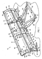
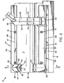
- the clearing device 10 shown in FIGS. 1, 2 and 3 has in generally a frame structure 14, one at the bottom of the frame 14 attached scratch sheet 16 and a concave to the front and inwardly curved scraper 18.
- the concave curve Clearing board 18 has a front end pointing in the direction of travel or clearing Surface 19 and a rear, the frame 14 facing Area 17 (back).
- the definitions used here are to be understood as follows: “Scratching Blade” is the interchangeable, lower edge section of the clearing device meant while Sheet “the concavely curved frontal surface 19 of the clearing board 18th and the scraper blade 16. Under plow or clearing device 10 are the frame 14, the clearing board 18 and the scraper blade 16 to understand.
- auxiliary elements include a support crossbeam 20, which with Suspensions 21 is provided on a vehicle, not shown are attached. Extend from the support crossbeam 20 struts 23 that pivot at 25 on a box-shaped Frame 26 are articulated.
- the box-shaped frame 26 is by means of a pivot connection 28 pivotable on the bottom portion the frame structure 14 attached.
- the pivot connection 28 allows forward or backward tilting of the Clearing device 10 about a horizontal axis.
- Cylinder 30, the side are mounted on the struts 23, allow a horizontal Swiveling the plow 10 about the swivel suspension 25, so that the angle of inclination of the plow 10 relative to Vehicle (or the direction of travel) can be adjusted to Snow to one side or to the other side of the plow 10 to be able to leave.
- a first mounting arm 33 attached to the box-like frame 26 is attached, and a second mounting arm 34, the attached to the upper end of the frame structure 14 serve for mounting one or more springs 36, which the clearing device 10 keep in an upright position. If the scratch sheet 16 on a Hitting an obstacle on the road, etc., the plow 10 swings the pivot 28 against the force of the springs 36 that the clearing device or the plow 10 after passing the obstacle in his Move the normal position back. The tension of the springs 36 is in in a known manner by means of screwed into the mounting arms 34 Adjustment arms 38 set.
- auxiliary elements described above are for generic Plows are known and therefore need no further explanation become. It should be noted, however, that it is lightweight Clearing board 18 is made possible, the auxiliary elements as well to construct the frame 14 in a manner that the Weight and manufacturing costs compared to building this Components in conventional steel clearing boards can be reduced can.
- the frame 14 shown in Figs. 1, 2 and 3 is similar constructed like a conventional frame for a snow clearing plow with steel clearing board.
- the scope of the invention but should not exclusively be based on a special frame construction be limited.
- the frame 14 a longitudinally extending upper mounting member 40 that A lower mounting element extends across the full width of the plow 41, which extends accordingly over the width of the plow, as well as several spaced apart and over the Width of the plow side by side, concave curved Cross struts 44, which are between the upper mounting member 40 and the lower mounting element 41 and extend to this are attached.
- the upper mounting element is usually an angle profile with a mounting leg 47 and one in the right Angle to this essentially radially extending Leg 48.
- the cross struts 44 are also here, as shown in the drawings to make angle profiles with a V-shaped Cross-section.
- the legs 49 of the "V" end in concave curved front end faces 50, the curvature of the Cross struts or the end faces similar to the curvature of the concave curved clearing board 18 is executed.
- the end faces 50 of the cross struts 44 are curved in an arc and have a radius of curvature that matches the radius of curvature of the Clearing boards 18 is adapted.
- Each cross strut 44 has an upper angle profile end 52, the cut along a radial line or a radial plane is through the center of the curvature of the front face 50 goes.
- the radially extending leg 48 of the Upper mounting element 40 is aligned with the upper end of the angle 52 created and welded to this, so that with this coplanar contact line the position of the fastening leg 47 is ensured relative to the clearing board 18.
- each cross strut 44 is cut in a similar manner, preferably along a radial plane through the Center of the radius of curvature of the front face 50 passes.
- the lower mounting member 41 has in the preferred Embodiment a lower angle profile 56 and a flat Mounting plate 57, which is preferably on the radially extending leg 60 of the angle profile 56 abuts so that the mounting leg 59 of the angle profile 56 and the mounting plate 57 are essentially coplanar.
- the frame 14 is composed in that the angle profiles be cut precisely so that the cross struts 44th are bent with the desired radius of curvature and that using conventional stops or fittings to keep the elements in their exact assignment to each other, the elements are welded together.
- FIGS. 1, 2 and 3 Frame around a conventional frame.
- the general structure of all frames is similar in some points. So there are preferably at least four cross struts 44 on at least one, but preferably two (upper and lower) Mounting plates (longitudinal struts) attached.
- the profile shapes of the mounting plates and cross struts can vary.
- the clearing board 18 is preferably made of a polyethylene plastic with ultra high molecular weight (UHMW: ultra high molecular weight) and is usually 9.55 mm thick (3/8 ").
- UHMW ultra high molecular weight
- a suitable UHMW plastic is among the registered Brand names HOSTALEN GUR412LS and GUR422 distributed and is available from Hoechst (in America).
- the UHMW polyethylene material has a very low coefficient of friction, a relatively high abrasion resistance and sufficient flexural strength and thermal stretch limit to Snow clearance conditions to work. With the preferred Embodiment, the material is initially flat Sheet material into the curved one shown in the drawings Arrangement rolled or rolled. The material would be without a support this curved shape does not last for an extended period of time maintained.
- FIGS. 1 to 3 Frame 14 the clearing board 18 on the upper fastening leg 47 and on the lower mounting plate 57 by means of Fasteners 61 mounted, preferably a Have square shank, preferably through square holes fits in the clearing board 18.
- cross struts 44 for a curved support of the clearing board 18 care when the plow is in use, taking the scraper the opportunity is open to himself during his deployment bend or "jump" to the operation of the plow to improve.
- gap X in the preferred embodiment appropriately designed such that it is between a minimal Distance near the top portion of the clearing board 18 and one maximum distance near the lower portion of the clearing board 18 varies, i.e. resembles half a sickle.
- Gaps can cause the clearing board to jump or bend over one wide area of the clearing board can be controlled, resulting in a improved application behavior of the clearing board when rolling up and Lateral removal of the snow with the front Surface 19 leads.
- FIGS. 21 and 22 The features of the plow described so far are known as also shown in FIGS. 21 and 22, in which the described Arrangement from the prior art is shown.
- the vertically extending gap i.e. the space between the clearing board 18 and the section thereof facing the Cross strut 44 can be clearly seen in FIG. 21 as distance X. 22 is shown even more clearly in the cross-sectional view, that the gap X is the distance between the Back 17 of the clearing board 18 and the curved front face 50 of the leg 49 of the cross strut 44 is. That gap X starts bending the clearing board 18 in operation.
- Foreign material which is provided with the reference symbol 62 in FIG. 21, collects in gap X and fills it up. This foreign material gets between the legs 49 of the cross strut 44 and is jammed there.
- the foreign material can not only street dirt, but also ice formations or chunks of ice, when operating the plow in severe weather conditions may occur.
- the foreign particles prevent the desired one Deflection of the clearing board 18 or leave the desired one Deflection only partially.
- the plow 10 is therefore due to the low friction properties of the clearing board 18 made of polyethylene even with the jammed foreign material work and work better than plows with conventional ones Steel sheets are equipped.
- clearing boards are thwarted or reduced.
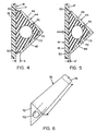
- FIGS. 1 to 6 provided that a body made of elastic or elastically deformable material 70 between the cross strut 44 and the clearing board 18 is inserted such that at least one Section of the gap X filled with the elastic material is.
- any block or solid-like, elastic or flexible material be understood, even at the temperatures that the clearing device or plow 10 is normally exposed, maintains a degree of elasticity. With elasticity is the property of the material meant to act under force deform and resume the original shape, when the force ceases. The elastically deformable material "springs" back to its original shape.
- elastic deformable material includes natural elastic materials, thermosetting materials and thermoplastics, in particular those characterized as natural or synthetic elastomers are or the natural or synthetic elastomers contain as constituents, polymers or composite materials thereof, including but not limited to natural rubber, Fluorine elastomers, polyurethane elastomers, styrene butadiene rubber, CIS-1,4-polybutaties, CIS-1,4, polyisoprene, butyl rubber, Ethylene propylene polymer, ethylene butyl polymer, neoprene, Nitrile rubber, silicone rubber, polysulfide rubber, Polyacrylate rubber and thermoplastic polyolefins.
- natural rubber Fluorine elastomers, polyurethane elastomers, styrene butadiene rubber, CIS-1,4-polybutaties, CIS-1,4, polyisoprene, butyl rubber, Ethylene propylene polymer, ethylene
- Elastic deformable material should also include liquid Foams and sprays that become flexible, elastically deformable solid-like materials in dried or hardened Solidify condition, as well as polymer foams and in particular one- or two-component, flexible polyurethane foams understood that are particularly suitable for retrofitting.
- the elastically deformable Material a thermoplastic elastomer, which is under the brand name Santoprene 101-64 available from Mile Rubber & Packaging Co. is. This material has a degree of compression of approximately 23% at 25 ° C and an elongation limit of about 400%.
- the Test hardness is about 50 (the usable hardness range is between 20 and 80, preferably between 40 to 60) and the material shows no brittle fracture at low temperatures.
- the elastically deformable material 70 has a triangular shape Blocks 72 with one extending through the block central, cylindrical opening 73.
- the triangular block is dimensioned such that it is between the legs 49 of the Cross strut 44 fits into it.
- the triangular block 72 extends in the idle state of the Plow 10 beyond the curved front faces 50, to completely fill the gap X and the rear or rear surface 17 of the clearing board 18 touch.
- Fig. 6 it can be clearly seen that the outer surfaces of the triangular block 72 are straight.
- the length dimension of the triangular Blocks 72 are larger than the vertically extending curved one Length over which the clearing board 18 bends, and this The length of the block is designated by the reference symbol Y in FIG. 6.
- Reference character "Y" is used throughout the description, around the vertical longitudinal extent of the elastically deformable To designate material 70 in the gap X.
- the excess material or the end regions 74 (only one end region 74 is shown in FIG.
- FIGS. 1 to 6 shows the triangular block 72 in contact with the back 17 of the Clearing boards across the vertical length Y of the gap X. This is only for drawing and illustration purposes. Indeed the triangular block 72 does not or need not necessarily the back 17 of the clearing board 18 over the Touch the vertical length Y of the gap X.
- FIGS. 4A and 5A show an alternative embodiment the invention in a representation that corresponds to FIGS. 4 and 5.
- the triangular block 72 is all over itself vertically extending longitudinal dimension Y changed to smaller To have outer surface dimensions. Even the modified block 72A has a central cylindrical passage 73A.
- the end sections 74 of the modified block 72A are like the triangular one Block 72 is formed for the aforementioned purposes.
- There the changed block 72A extends in the gap X, the Gap X reduced by an amount that in the drawing with the reference symbol A is designated in FIGS. 4A and 5A, this Distance A between the back 17 of the clearing board and one front outer surface 75 formed on the modified block 72A is.
- Gap A can get foreign material like road debris, here with Reference number 62 denotes, or ice plates, here with reference numbers 64 labeled collect.
- the gap X is consequently thereby completely filled in that foreign material 62, 64 before modified block 72A protrudes. If the arrow in Fig. 5A shown snow force on the front surface 19 of the Clearing board 18 acts, the clearing board 18 can still bend resiliently and the gap X to the dimension X ', as shown out.
- the reduced gap X 'in FIG. 5A is larger than the reduced gap X 'in Fig. 5, but the scraper board is further able to bend and as a result suitable the roll-up and lateral removal movement of the Improve snow over its area.
- the invention is therefore not necessarily limited to that elastically deformable material fills the gap X, because that Clearing board still according to its design advantages will bend or jump if elastically deformable material 70 the gap X as shown in FIGS. 4A and 5A only partially filled. It is understood that the suspension quality of the clearing board 18 is optimized when the elastically deformable Material 70 essentially completely fills the gap.
- FIG. 6 Another modification of the triangular block 72 is with the triangular block 72B shown in FIG.
- the additional Change is the removal of the end portions 74 of the triangular block 72 which, as with reference to FIG 1 to 6 has been explained, between the cross strut 44 and the upper fastening leg 47 on the one hand and between the cross strut 44 and the lower mounting plate 57 is clamped.
- the modified block 72B therefore only extends over the length Y as shown in Fig. 6. Hold the legs 49 of the cross strut 44 the modified triangular block 72B within the Cross strut 44 fixed.
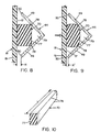
- a rectangular block made of elastically deformable Material 70 has.
- the rectangular block is 77 dimensioned such that it extends over a length Y or alternatively extends over a greater length to the one hand the radial extending leg 48 of the upper mounting element 40 and on the other hand the radially extending lower leg 60 of the lower mounting element 41 in the assembled rest position to touch.
- the cross section of the rectangular block 77 is dimensioned such that the two rear edges 78 touch the V-leg 49 of the cross strut 44, while doing so a sealed cavity 79 between the rectangular Release block 77 and the crown of the cross strut in the Foreign material cannot enter.
- the vertex cavity 79 enables a deformation of the elastically deformable material of the rectangular block 77 when the scraper 18, such as shown in Fig. 9 bends regardless of the presence of any Foreign material between the leg end faces 50, the clearing board 18 and the rectangular block 77.
- Embodiments has the elastically deformable material Form of an elastically deformable strip 80.
- the elastic deformable strip 80 is on one side of a double-sided Adhesive tape 81 attached, which is preferably a elastically deformable coated on both sides with an adhesive or damping material.
- the other side of the double-sided Band 81 is attached to the back 17 of the clearing board 18.
- the band 81 and the one have elastically deformable Strips 80 together a thickness slightly larger than the gap is X, so that in the assembled idle state, like it is shown in Fig. 12, the front curved end faces 50 of the cross strut 44 touch the strip 80 firmly.
- the double-sided Band 81 enables precise positioning of the elastic deformable strip 80 for the installation of the clearing board 18 in the frame 14. Depending on the assembly technology, this can double-sided adhesive tape 81 replaced by other assembly techniques become. Alternatively, the elastically deformable material of the double-sided adhesive tape 81 alone the elastically deformable Form material 70 and a separate or additional damping Strip 81 (with an adhesive coating on only one side) can replace the elastically deformable strip 80. The elastic deformable strips 80 can also just instead with an adhesive layer for attachment to the back 17 of the Clearing boards can be coated. From Fig. 11 it is clear that the Length Y of the elastically deformable strip 80 is not greater can be as the distance between the exposed edge of the upper mounting leg 47 and the exposed edge of the lower mounting plate 57.
- FIGS. 1 to 17 Another embodiment of the invention is in 13 to 17 shown.
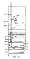
- the one shown in Figs. 13 and 14 Frame 14A has one of frame 14 of FIGS. 1 through 12 different structure, but is in the essential elements as the frame described above, so that the Description of the frame 14A shown in Figs. 13 and 14 for same components same reference numerals as in the description of the frame 14 can be used in FIGS. 1 to 3.
- the cross strut 44A has no V-shape, but is included as a flat plate executed only one leg 49A, the front or front End face 50A is curved.
- the cross strut 44A is on one locked lower mounting member 41, which, as described, has an angle profile 56 and a flat lower mounting plate 57.
- the upper mounting element 40A (now in the form of segments between adjacent cross struts 44A) is approximately in the middle, i.e. halfway up the Cross brace 44A positioned with its mounting leg 47A and its radially extending leg 48A with the Leg 49A of the cross strut 44A are welded, as with Reference numeral 83 in Fig. 14 is indicated.
- the cross strut 44A therefore differs from the cross strut described above 44 through an upper end region 84, which extends radially extending leg 48A protrudes. It is more important that the cross strut 44A of that described in FIGS. 1 to 12 Cross strut 44 differs in that the front curved Face 50A a progressively increasing gap X between itself and the rear surface 17 of the clearing board 18.
- the progressive gap X is in that assembled hibernation right from the start in the frame construction constructed so that the clearing board 18 a little Bounce back or bend at its top section and a significantly greater bending at its lower, transversely extending Section can have.
- the intentional one Gap improves the property of the plow, the snow in roll up the curvature of the clearing board 18.
- the provision of one increasing gap is known in itself.
- the increasing gap X serves its intended purpose. It is understood that the Gap X on purpose (as in this embodiment) or at random (as in the embodiments in FIGS. 1 to 12) due to of manufacturing tolerances, the assembly process etc. non-uniform can be.
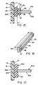
- the elastically deformable material 70 is in the form of a grooved Strip 85 with a formed on one of its sides, extending groove or channel 86.
- the Groove 86 has side walls 87 which define the leg 49A of the cross strut 44A, and a groove base 88 which is in contact with the front curved end surface 50A of the cross strut 44A.
- the Grooved strip 85 is preferably dimensioned such that its thickness between an outer strip back 89, which the back surface 17 of the clearing board 18 is opposite, and the Groove bottom 88 varies progressively according to the gap X. An important difference is that that shown as dimension Y in FIG.
- the length of the grooved strip 85 in the gap X is not the vertical length of the clearing board 18 as in the previously described Embodiments must correspond.
- the trained as an increasing gap ensures Gap X bending the clearing board 18 over its lower itself transversely extending section. Accordingly, the grooved needs Strip 85 only over the lower section of the cross strut 44A to accommodate the bending of the clearing board this scraper section, as shown in Figs. 13 and 14, sure.
- a collection of foreign material in the section of the gap X, which is not partially or completely with elastically deformable material 70 is filled, the desired Do not negatively affect the operation of the plow 10.
- Strip 85A in Fig. 17 is a modification of the grooved strip 85 shown, which to that explained with reference to FIGS. 11 and 12 and described embodiment is based.
- Strip 85A in Fig. 17 the groove is omitted.
- the stripe 85A can be attached to the rear surface 17 of the clearing board 18 a double-sided adhesive tape 81 (not shown) or by means of an adhesive coating on the outer strip back 89A be attached.
- FIGS. 1 to 12 the frame in Fig. 18 is with the frame 14 according to FIGS. 1 to 12 almost identical. Extends differently the fastening leg 47 of the upper mounting element 40 vertically upwards and not, as in FIGS. 1 to 12, in the vertical direction downward. This is only intended to illustrate that 14 variations are possible with the frame. It is not for any of them in both embodiments, the alignment of the top Mounting element 40 to change to an elastically deformable material in a deliberately constructed, varying gap X, as shown in Fig. 13 apply. With Fig. 18 clarifies that the concave, i.e.
- the triangular block 72A shown in Fig. 19 has a thickness which preferably extends from its upper end 89 to its lower End 90, adapted to the increasing change in gap X, reduced. This dimensional coordination is preferred, for functionality as shown in the 4A and 5A, this is not necessary and the width of the triangular blocks 72A could be constant.
- Fig. 19 shows also that the triangular block is one extending inside may have central opening 73A.
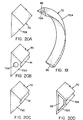
- 20A, 20B, 20C and 20D are alternative embodiments of the elastically deformable material 70 in shape of modified triangular blocks 72.
- a solid triangular block 72B is shown. If the scraper 18 bends, the elastically deformable Material spread on both sides of the cross strut 44, wherein the elastically deformable material behind the front curved end face 50 bulges.
- the dimensionally stable shown in Fig. 20 C. triangular block 72C has one in its apex trained semicircular extending over its entire length Throat 91.
- triangular block 72D is a combination of the triangular blocks 72A and 72C.
- 20C is a triangular block 72E shown which is a central triangular Has recess 93, the outer surfaces of the triangular Blocks 72E as wall sections with substantially the same Thicknesses are formed.
- the recess 93 is not complete triangular, as optional a semicircular throat 91A may be provided in the apex, as is related to FIG 20C has been explained, so that a semicircular wall section is formed in the recess 93.
- the selection of the special construction depends on various factors including the dimensions of the elastically deformable mass and the properties of the selected elastically deformable Material.
- the elastically deformable material should be of its Hardness and bending stiffness should not be such that bending of the clearing board 18 is prevented, but the elastically deformable Material should preferably allow that Bend the clearing board 18 in the same or approximately the same dimensions as if there was no foreign material in gap X.
- the elastically deformable material 70 must be sufficient Have stability that is a build-up of foreign material completely prevented in gap X or prevented as far as that the gap X is only to a certain extent with foreign material crowded.
- the construction of the body of the elastically deformable Material as through the numerous embodiments has been disclosed taking these considerations into account.
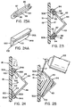
- the 23 and 23A, 24 and 24A and 25 are embodiments shown for retrofit applications of the invention.
- the 23 and 23A disclose an elastically deformable insert 94, which is U-shaped and has a longitudinal groove 95, the The bottom of the "U” touches the clearing board 18 or alternatively at least fills a section of the gap X.
- the cross strut 44 is a Angular profile with frontal end faces 50 that are desired Curvature are cut. 23 is can be seen that the front face 50A of each Leg 49 of the cross strut is provided with an oblique edge. This inclined edge matches the inclined groove base 96 in the groove 95 of the elastically deformable insert 94.
- This Design enables the side walls 97, 98 of the Let groove 95 spread open so that the elastically deformable insert 94 are clamped onto the leg 49 of the cross strut 44 can.
- the sole of the U-shaped, elastically deformable insert 94 is then pressed against the rear surface 17 of the clearing board, so that the sloping groove bottom 96 clinging against the front face 50A of the leg 49 creates.
- FIGS 23 and 23A Another elastically deformable insert 94A for retrofitting is shown in Figures 24 and 24A.
- the elastically deformable Insert 94A has two tapered outer surfaces 100, 101 converging at the tip 102 and a wedge-shaped form elastically deformable insert.
- One outer surface 100 is facing the rear surface 17 of the clearing board and the other outer surface 101 includes a groove 95A which is like that in FIGS 23 and 23A shown and described groove of the elastically deformable Insert 94 is formed.
- the wedge shape of the elastic deformable insert 34A allows a comparative easy retrofitting. It is understood that neither the elastic deformable insert 94 or insert 94A on the retrofit application are limited, but also as elastically deformable Material can be used with new plows.
- Fig. 25 shows still another embodiment, which under the inventive definition of an elastically deformable material falls.
- this embodiment which is particularly for Is suitable cross struts that have an angle profile structure, is the gap X on one side of the cross strut 44 by means of a removable clip or other suitable sheet or bar temporarily closed while in the interior of the Cross strut 44 from the other, open side of the cross strut 44 forth from a foam container 105 an expandable polymer Foam is injected.
- the volume changes of the foam which as a liquid from the pressurized Container 105 is released when it meets Humidity in a foam covering the interior of the cross brace 44 completely filled out.
- a coarse-celled or flexible Foam is used so that the foam has the desired suspension properties to expand and contract.
- the degree the flexibility of the foam depends on its composition from. For example, known one-component or two-component flexible polyurethane foams can be used.
- the previously described Configurations of the elastically deformable material Have a size that extends laterally beyond the gap X (likewise as within) or optionally behind the gap extends.
- the composition of elastically deformable Material within each of the "blocks" from the for different "blocks” disclosed material or structure varies not only the accumulation of foreign material in the Gap is prevented, but this also becomes a desired one Deflection movement of the clearing board leads.
- the cross strut 44 can also be an "L-profile", “U-profile” or “H-profile” or the cross strut is manufactured in a different way.
Landscapes
- Architecture (AREA)
- Civil Engineering (AREA)
- Structural Engineering (AREA)
- Engineering & Computer Science (AREA)
- Soil Working Implements (AREA)
- Road Paving Structures (AREA)
- Cleaning Of Streets, Tracks, Or Beaches (AREA)
- Auxiliary Devices For And Details Of Packaging Control (AREA)
- Knives (AREA)
- Distribution Board (AREA)
- Control And Other Processes For Unpacking Of Materials (AREA)
- Paper (AREA)
- Storage Of Harvested Produce (AREA)
- Shielding Devices Or Components To Electric Or Magnetic Fields (AREA)
- Disintegrating Or Milling (AREA)
Claims (31)
- Dispositif d'enlèvement, en particulier en tant que dispositif rapporté pour véhicules, pour enlever la neige, des accumulations, de la terre et analogues, sur les routes, chemins et surfaces analogues, comprenant une lame d'enlèvement (18) en matériau plastique, fixée sur un châssis stable (14 ; 14A) qui est monté ou peut être monté par un côté sur un véhicule et présente au moins une traverse (44 ; 44A) s'étendant sensiblement verticalement, espacée de la lame d'enlèvement (18) pour délimiter un intervalle (X) entre elle et la lame d'enlèvement (18), caractérisé en ce qu'au moins une région de l'intervalle (X) est au moins partiellement comblée avec un matériau (70) élastiquement déformable.
- Dispositif d'enlèvement selon la revendication 1, caractérisé en ce que le châssis (14 ; 14A) comprend une paire d'éléments de montage (40, 41 ; 40A, 41A) s'étendant longitudinalement, qui sont écartés verticalement l'un de l'autre par l'une ou les plusieurs traverses (44 ; 44A) qui est ou sont agencées de façon repartie le long des éléments de montage (40, 41 ; 40A, 41A), la lame d'enlèvement (18) étant fixée aux éléments de montage (40, 41 ; 40A, 41A), la lame d'enlèvement (18) et les traverses (44, 44A) étant incurvées de façon concave pour délimiter l'intervalle (X) en forme d'arc.
- Dispositif d'enlèvement selon la revendication 1, caractérisé en ce que le cadre comprend des éléments de montage s'étendant longitudinalement, supérieurs et inférieurs à l'état monté sur le véhicule, et au moins un élément de montage s'étendant non-longitudinalement, il est prévu la lame d'enlèvement incurvée flexible, dont la face frontale présente une partie incurvée de façon concave, et un dispositif de raccordement de la lame d'enlèvement pour assujettir la lame d'enlèvement sur le châssis, l'élément s'étendant non-longitudinalement est fixé aux éléments de montage supérieur et inférieur s'étendant longitudinalement, le châssis comprend une traverse se tenant à une distance de la lame d'enlèvement et délimitant un intervalle, et il est prévu un matériau d'amortissement pour amortir le mouvement de la lame d'enlèvement dans le châssis.
- Dispositif d'enlèvement selon l'une des revendications 1 à 3, caractérisé en ce que l'intervalle (X) est comblé sensiblement en totalité avec le matériau élastiquement déformable (70).
- Dispositif d'enlèvement selon l'une des revendications 1 à 3, caractérisé en ce que l'intervalle (X) est irrégulier en ce qui concerne la distance entre la lame d'enlèvement (18) et l'au moins une traverse (44) sur son étendue longitudinale verticale.
- Dispositif d'enlèvement selon l'une des revendications 1 à 5, caractérisé en ce que l'intervalle (X) s'accroít de l'extrémité de la lame d'enlèvement (18) qui est supérieure à l'état monté sur le véhicule, à l'extrémité inférieure.
- Dispositif d'enlèvement selon l'une des revendications 1 à 6, caractérisé en ce que le matériau élastiquement déformable (70) est installé sur certaines choisies des traverses (44, 44A) délimitant l'intervalle (X).
- Dispositif d'enlèvement selon l'une des revendications 1 à 7, caractérisé en ce que le matériau élastiquement déformable (70) est fixé à la traverse (44, 44A) et/ou à la lame d'enlèvement (18).
- Dispositif d'enlèvement selon l'une des revendications 1 à 8, caractérisé en ce que le matériau élastiquement déformable (70) est agencé dans des régions choisies de quelques intervalles (X) choisis, et peut être comprimé lorsque de la neige, des rochers ou analogues provoquent une flexion de la lame d'enlèvement (18) pendant le service de l'instrument de déblaiement (10).
- Dispositif d'enlèvement selon l'une des revendications 1 à 9, caractérisé en ce que les traverses (44) sont constituées de cornières, chaque traverse (44) possède une section transversale en forme V et les faces frontales (50) des ailes (49) formant le V sont incurvées de façon concave, les faces frontales (50) et la face arrière (17) de la lame d'enlèvement (18) délimitent l'intervalle (X) en forme d'arc, et le matériau élastiquement déformable (70) est intercalé entre les faces frontales (50) des ailes de chaque traverse (44) et la face arrière (17) de la lame d'enlèvement (18), pour combler l'intervalle (X).
- Dispositif d'enlèvement selon l'une des revendications 1 à 9, caractérisé en ce que la traverse (44A) est une plaque plate constituant une seule aile (49A) avec une face frontale avant (50A) incurvée de façon concave, faisant face à la lame d'enlèvement (18), le matériau élastiquement déformable est disposé entre la face frontale intérieure (50A) de chaque traverse (44A) et la lame d'enlèvement (18) pour sensiblement remplir au moins une région de l'intervalle (X) lorsque la lame d'enlèvement (18) est montée dans le cadre (14, 14A).
- Dispositif d'enlèvement selon la revendication 10 ou 11, caractérisé en ce que le matériau élastiquement déformable (70) est un bloc de matière (72 ;72A ;72B ;72C ;72D ;72E) qui est disposé à l'intérieur du V de chaque traverse (44) et de préférence dépasse latéralement des faces frontales (50) des ailes pour sensiblement obturer l'intervalle (X).
- Dispositif d'enlèvement selon la revendication 12, caractérisé en ce que le bloc de matière (72 ;72A ; 72D ;72E) présente une ouverture (73 ; 73A ; 93) s'étendant intérieurement, déformable lors de la compression du matériau élastiquement déformable (70).
- Dispositif d'enlèvement selon la revendication 12 ou 13, caractérisé en ce que le bloc de matière (72 ;72A ;72B ;72C ;72D ;72E) présente une section transversale sensiblement adaptée à la forme en V de la traverse (44), de sorte que le bloc de matière peut être inséré dans le V de la traverse (44).
- Dispositif d'enlèvement selon l'une des revendications 10 à 14, caractérisé en ce que le matériau élastiquement déformable (70) est une bande (80, 85 ;85A) en matériau élastiquement déformable intercalée entre les faces frontales (50 ; 50A) des ailes et la lame d'enlèvement (18).
- Dispositif d'enlèvement selon la revendication 15, caractérisé en ce que la bande (80 ;85 ; 85A) en matériau élastiquement déformable a une épaisseur qui correspond approximativement à l'intervalle (X), la bande (80, 85 ;85A) étant de préférence collée avec la lame d'enlèvement (18).
- Dispositif d'enlèvement selon la revendication 15 ou 16, caractérisé en ce que la bande (80 , 85 ;85A) comprend un ruban (81) avec de l'adhésif sur les deux côtés pour la fixation du matériau élastiquement déformable (70) sur la lame d'enlèvement (18), la bande (80, 85 ;85A) présentant au moins dans une région de l'étendue longitudinale (Y) de l'intervalle une épaisseur plus grande que l'intervalle (X) de sorte que la bande (80 ;85 ; 85A) est comprimée lorsque la lame d'enlèvement (18) est installée dans le cadre (14 ; 14A).
- Dispositif d'enlèvement selon l'une des revendications 10 à 17, caractérisé en ce que le matériau élastiquement déformable (70) a plusieurs côtés et comprend une rainure (86, 95, 95A) réalisée dans son premier côté, le fond de la rainure (88 ;96) étant adapté au contact avec les faces frontales (50 ; 50A) des ailes et les flancs de la rainure (87 ; 97 ; 98) étant adaptés au contact avec les flancs des ailes (49 ; 49A) de la traverse (44 ; 44A).
- Dispositif d'enlèvement selon la revendication 18, caractérisé en ce que la rainure possède une première partie de paroi qui est sensiblement perpendiculaire au premier côté, et une deuxième partie de paroi qui est sensiblement en angle par rapport au premier côté, la bande pouvant être coincée avec une aile de la traverse dans un ajustement à contact dans la rainure, pour post-équiper une lame d'enlèvement installée dans le cadre.
- Dispositif d'enlèvement selon l'une des revendications 15 à 19, caractérisé en ce que la bande (94A) présente une section transversale triangulaire avec une rainure (95A) réalisée dans un côté (101) de la bande, et possède un second côté (100) se trouvant en contact avec la lame d'enlèvement, de sorte que le premier et le deuxième côté (100 ; 101) forment un sommet (102) d'un triangle, grâce à quoi la bande (94A) peut être insérée entre la lame d'enlèvement (18) et une aile (49 ; 49A) d'une traverse (44 ; 44A).
- Dispositif d'enlèvement selon l'une des revendications 1 à 20, caractérisé en ce que la traverse a la forme d'une plaque en L dont la base, incurvée de façon concave, est disposée face à la lame d'enlèvement, le matériau élastiquement déformable étant disposé entre la base de la traverse et la lame d'enlèvement, pour sensiblement remplir au moins une région de l'intervalle lorsque la lame d'enlèvement est installée dans le cadre.
- Dispositif d'enlèvement selon l'une des revendications 1 à 21, caractérisé en ce que le matériau élastiquement déformable (70) est une mousse polymère.
- Dispositif d'enlèvement selon l'une des revendications 1 à 21, caractérisé en ce que le matériau élastiquement déformable (70) est à base de caoutchouc.
- Dispositif d'enlèvement selon l'une des revendications 1 à 23, caractérisé en ce que la lame d'enlèvement en matière plastique (18) est en polyéthylène.
- Dispositif d'enlèvement selon l'une des revendications 1 à 24, caractérisé en ce que la lame d'enlèvement (18) comprend un racleur (16) fixé à la semelle de la lame d'enlèvement (18).
- Dispositif d'enlèvement selon la revendication 25, caractérisé en ce que le racleur (16) est réalisé sous la forme d'un composant s'étendant sensiblement longitudinalement, qui s'étend de façon sensiblement complète sur la semelle de la lame d'enlèvement (18).
- Procédé pour assembler un dispositif d'enlèvement, comprenant les étapes suivantes :a. Préparer une lame d'enlèvement (18) en polyéthylène ;b. Construire un cadre (14 ;14A) en fixant plusieurs traverses (44 ; 44A) s'étendant non-longitudinalement sur un côté d'un élément de montage supérieur (40 ; 40A) s'étendant longitudinalement et d'un élément de montage inférieur (41 ; 41A) s'étendant longitudinalement ;c. Fixer la lame d'enlèvement (18) au côté des éléments de montage (40, 41 ; 40A ; 41A) situé en vis à vis en formant un intervalle (X) entre les faces frontales en vis à vis, (50 ; 50A) des traverses (44 ; 44A) et du côté arrière (17) de la lame d'enlèvement (18) ; etd. Rapporter un matériau élastiquement déformable (70) sur la lame d'enlèvement (18) et/ou les traverses (44 ; 44A) avant ou après installation de la lame d'enlèvement (18) dans le cadre (14 ; 14A), en remplissant au moins partiellement une région de l'intervalle (X).
- Procédé selon la revendication 27, caractérisé en ce que la lame d'enlèvement est généralement plane à l'état non monté et on la roule ou on la cintre en forme incurvée concave lorsqu'on la fixe sur le cadre (14 ; 14A) et les traverses (44 ; 44A) présentant une face frontale (50 ; 50A) incurvée de façon concave, l'intervalle (X) étant réalisé en forme arquée.
- Procédé selon la revendication 27, caractérisé en ce que la lame d'enlèvement (18) présente une forme incurvée de façon concave à l'état non monté et la traverse (44 ; 44A) présente une face frontale (50 ; 50A) incurvée de façon concave, l'intervalle (X) étant arqué.
- Procédé selon l'une des revendications 27 à 29, caractérisé en ce que le matériau élastiquement déformable (70) est une mousse polymère extensible ou un bloc de matière en substance caoutchouc formé spécialement.
- Procédé selon l'une des revendications 27 à 30, caractérisé en ce qu'une partie du matériau élastiquement déformable (70) se trouve comprimée lorsque la lame d'enlèvement (18) est installée dans le cadre (14 ; 14A).
Applications Claiming Priority (2)
| Application Number | Priority Date | Filing Date | Title |
|---|---|---|---|
| US215812 | 1998-12-18 | ||
| US09/215,812 US6134813A (en) | 1998-12-18 | 1998-12-18 | Plastic moldboard plow |
Publications (3)
| Publication Number | Publication Date |
|---|---|
| EP1010809A2 EP1010809A2 (fr) | 2000-06-21 |
| EP1010809A3 EP1010809A3 (fr) | 2002-03-20 |
| EP1010809B1 true EP1010809B1 (fr) | 2004-08-18 |
Family
ID=22804505
Family Applications (1)
| Application Number | Title | Priority Date | Filing Date |
|---|---|---|---|
| EP99113621A Expired - Lifetime EP1010809B1 (fr) | 1998-12-18 | 1999-07-12 | Dispositif d'enlèvement avec une lame en matière plastique |
Country Status (9)
| Country | Link |
|---|---|
| US (2) | US6134813A (fr) |
| EP (1) | EP1010809B1 (fr) |
| JP (1) | JP3236964B2 (fr) |
| AT (1) | ATE274106T1 (fr) |
| CA (1) | CA2266738C (fr) |
| DE (1) | DE59910268D1 (fr) |
| HU (1) | HUP9903301A3 (fr) |
| NO (1) | NO326716B1 (fr) |
| PL (1) | PL189866B1 (fr) |
Families Citing this family (48)
| Publication number | Priority date | Publication date | Assignee | Title |
|---|---|---|---|---|
| US20040079540A1 (en) * | 1993-08-23 | 2004-04-29 | Zambahlen Stanley E. | Manure scraper |
| US6354025B1 (en) | 1998-08-04 | 2002-03-12 | Cives Corporation | Adjustable mounting arrangement for moldboard |
| US6574890B2 (en) * | 1999-04-15 | 2003-06-10 | Bateman Services, Inc. | Combination snowplow and bucket |
| US6594923B1 (en) | 1999-11-29 | 2003-07-22 | The Louis Berkman Company | Snowplow mount |
| US6354024B1 (en) * | 1999-11-29 | 2002-03-12 | The Louis Berkman Company | Snowplow mount |
| CA2313291C (fr) * | 2000-06-30 | 2007-09-18 | Champion Road Machinery Limited | Ensemble de lame niveleuse |
| KR100408486B1 (ko) * | 2001-01-19 | 2003-12-06 | (주)태성공업 | 트랙터 로우더 탈부착형 제설장치 |
| US6688021B2 (en) * | 2001-04-19 | 2004-02-10 | General Electric Company | Locomotive snow removal enhancement |
| US6817118B2 (en) * | 2001-11-12 | 2004-11-16 | Charles M. Schmeichel | Self-adjusting snow plow |
| US7676962B2 (en) | 2001-11-12 | 2010-03-16 | Agri-Cover, Inc. | Snow plow having reinforced mold board |
| US7669353B2 (en) | 2001-11-12 | 2010-03-02 | Agri-Cover, Inc. | Snow plow having hitch tongue connecting member |
| US7627965B2 (en) | 2001-11-12 | 2009-12-08 | Agri-Cover, Inc. | Plow blade having integrally formed attachment channel |
| US7681335B2 (en) | 2001-11-12 | 2010-03-23 | Agri-Cover, Inc. | Snow plow having attachable biasing member |
| US7784199B2 (en) | 2001-11-12 | 2010-08-31 | Agri-Cover, Inc. | Snow plow having pivotal mounting apparatus |
| US7735247B2 (en) * | 2001-11-12 | 2010-06-15 | Agri-Cover, Inc. | Snow plow for all terrain vehicle |
| US7707753B2 (en) * | 2001-11-12 | 2010-05-04 | Agri-Cover, Inc. | Multifunctional plow blade positioning apparatus and method |
| US7676964B2 (en) * | 2001-11-12 | 2010-03-16 | Agri-Cover, Inc. | Snow plow having wear minimizing apparatus |
| US7735245B2 (en) * | 2001-11-12 | 2010-06-15 | Agri-Cover, Inc. | Snow plow having catch structure |
| US7676963B2 (en) | 2001-11-12 | 2010-03-16 | Agri-Cover, Inc. | Snow plow including mold board having back plate |
| US7743534B2 (en) * | 2001-11-12 | 2010-06-29 | Agri-Cover, Inc. | Snow plow having two-piece mold board |
| US8875419B2 (en) | 2001-11-12 | 2014-11-04 | Agri-Cover, Inc. | Snow plow |
| USD491520S1 (en) | 2002-05-01 | 2004-06-15 | William B. Hutton | Wood pellet |
| US6775933B2 (en) * | 2002-07-10 | 2004-08-17 | Sno-Way International, Inc. | Snow plow having an in-line frame design and method of making the same |
| US20040006895A1 (en) * | 2002-07-10 | 2004-01-15 | Schultz Lynn W. | Back blade wearstrip for efficient backward operation of snow plows and method for facilitating the same |
| US6618965B1 (en) | 2002-07-10 | 2003-09-16 | Sno-Way International, Inc. | Cushion stop and method for absorbing bidirectional impact of snow plow blade tripping |
| US6860039B2 (en) | 2002-07-10 | 2005-03-01 | Sno-Way International, Inc. | Snow plow quick connect/disconnect hitch mechanism and method |
| US6874260B2 (en) * | 2002-07-12 | 2005-04-05 | Covenant Resolutions, Inc. | Plow system for a vehicle |
| US6941685B2 (en) * | 2002-10-29 | 2005-09-13 | Douglas Dynamics, L.L.C. | Snowplow assembly |
| US8037625B2 (en) | 2003-03-31 | 2011-10-18 | Agri-Cover, Inc. | Snow plow having pivotal mounting apparatus |
| CA2426735C (fr) * | 2003-04-24 | 2013-05-21 | Willem Jager | Chasse-neige |
| FI116800B (fi) * | 2004-10-11 | 2006-02-28 | Patria Vammas Oy | Lumiauran siipi |
| CA2566993C (fr) | 2005-11-03 | 2012-10-02 | Pro-Tech Manufacturing And Distribution, Inc. | Pousse-neige reversible et accouplement |
| CA2603691A1 (fr) * | 2006-09-21 | 2008-03-21 | James A. Kost | Chasse-neige en thermoplastique |
| ITBO20070654A1 (it) * | 2007-09-25 | 2009-03-26 | Assaloni 1920 S R L | Lama sgombraneve estensibile |
| US8999501B2 (en) * | 2007-11-30 | 2015-04-07 | Ricoh Company, Ltd | Urethane foam member, seal structure, toner storage container, process cartridge, image forming apparatus |
| US20090307934A1 (en) * | 2008-06-17 | 2009-12-17 | Wendorff Terry C | Durable, coated snow plow blades and method of forming a coated snow plow blade |
| US7685748B1 (en) | 2008-12-17 | 2010-03-30 | Cycle Country Accessories Corporation | Vehicular plow |
| US7793440B1 (en) | 2009-08-19 | 2010-09-14 | Louis Berkman Winter Products Company | Method and apparatus for attaching a moldboard to a moldboard frame |
| US20130174452A1 (en) * | 2012-01-06 | 2013-07-11 | Kennametal Inc. | Plow Blade Assembly |
| US9151006B2 (en) | 2012-02-09 | 2015-10-06 | Pro-Tech Manufacturing And Distribution, Inc. | Material pusher with control system |
| CA2806030A1 (fr) * | 2012-02-13 | 2013-08-13 | David Hansen | Chasse-neige en composite et methode |
| US9139175B2 (en) * | 2012-04-25 | 2015-09-22 | International Business Machines Corporation | Automotive vehicle skid recovery system |
| SI24290A (sl) * | 2013-02-01 | 2014-08-29 | Riko Ekos D.O.O. | Koničast snežni plug |
| CN106284177A (zh) * | 2016-08-26 | 2017-01-04 | 王玮 | 一种结构强度高的推雪铲 |
| US10550544B1 (en) | 2019-04-17 | 2020-02-04 | Edwin A. Erickson | Spring loaded feeding device |
| US10544563B1 (en) | 2019-04-17 | 2020-01-28 | Edwin A. Erickson | Spring loaded feeding device |
| US20230064889A1 (en) * | 2021-08-31 | 2023-03-02 | Ironhawk Industrial Distribution, LLC | Road maintenance guard |
| US20250171970A1 (en) * | 2023-11-27 | 2025-05-29 | Caterpillar Inc. | Motor grader snow wing liner |
Family Cites Families (9)
| Publication number | Priority date | Publication date | Assignee | Title |
|---|---|---|---|---|
| US3432947A (en) * | 1966-07-05 | 1969-03-18 | Meyer Products Inc | Deflector for blown snow over snowplow blades |
| US3465456A (en) * | 1966-11-18 | 1969-09-09 | Meyer Products Inc | Blade for snowplows and similar devices |
| US3994081A (en) * | 1975-09-12 | 1976-11-30 | Middleton Carlisle A | Hand-propelled snow plow with motor oscillated blade |
| FR2394239A1 (fr) * | 1977-06-15 | 1979-01-12 | Weber Marcel | Perfectionnement aux faucheuses a disques entraines par le bas |
| US4845866A (en) * | 1988-03-28 | 1989-07-11 | The Louis Berkman Company | Plastic moldboards for snow plows and the like |
| US4803790A (en) * | 1988-03-28 | 1989-02-14 | The Louis Berkman Company | Plastic moldboards for snow plows and the like |
| US4844195A (en) * | 1988-06-17 | 1989-07-04 | Komatsu Dresser Company | Resilient mounting of crawler tractor frame |
| US5088215A (en) * | 1990-12-03 | 1992-02-18 | The Lewis Berkman Company | Plastic moldboards for snowplows and the like |
| US5692855A (en) * | 1994-06-21 | 1997-12-02 | Farmers' Factory Co. | Automatic quick-connect coupler for implements |
-
1998
- 1998-12-18 US US09/215,812 patent/US6134813A/en not_active Expired - Fee Related
-
1999
- 1999-03-23 CA CA002266738A patent/CA2266738C/fr not_active Expired - Fee Related
- 1999-05-10 JP JP12854999A patent/JP3236964B2/ja not_active Expired - Fee Related
- 1999-05-19 NO NO992398A patent/NO326716B1/no not_active IP Right Cessation
- 1999-07-12 EP EP99113621A patent/EP1010809B1/fr not_active Expired - Lifetime
- 1999-07-12 AT AT99113621T patent/ATE274106T1/de not_active IP Right Cessation
- 1999-07-12 DE DE59910268T patent/DE59910268D1/de not_active Expired - Fee Related
- 1999-09-29 HU HU9903301A patent/HUP9903301A3/hu unknown
- 1999-11-30 PL PL99336867A patent/PL189866B1/pl not_active IP Right Cessation
-
2000
- 2000-06-19 US US09/596,749 patent/US6564479B1/en not_active Expired - Lifetime
Also Published As
| Publication number | Publication date |
|---|---|
| HU9903301D0 (en) | 1999-11-29 |
| US6134813A (en) | 2000-10-24 |
| EP1010809A3 (fr) | 2002-03-20 |
| EP1010809A2 (fr) | 2000-06-21 |
| DE59910268D1 (de) | 2004-09-23 |
| NO326716B1 (no) | 2009-02-02 |
| JP2000178935A (ja) | 2000-06-27 |
| PL336867A1 (en) | 2000-06-19 |
| ATE274106T1 (de) | 2004-09-15 |
| PL189866B1 (pl) | 2005-09-30 |
| NO992398D0 (no) | 1999-05-19 |
| NO992398L (no) | 2000-06-19 |
| CA2266738A1 (fr) | 2000-06-18 |
| US6564479B1 (en) | 2003-05-20 |
| JP3236964B2 (ja) | 2001-12-10 |
| CA2266738C (fr) | 2003-07-15 |
| HUP9903301A3 (en) | 2002-08-28 |
| HUP9903301A2 (hu) | 2000-09-28 |
Similar Documents
| Publication | Publication Date | Title |
|---|---|---|
| EP1010809A2 (fr) | Dispositif d'enlèvement avec une lame en matière plastique | |
| EP2079628B1 (fr) | Véhicule à chenilles | |
| DE4204109C2 (de) | Schneepflug | |
| DE2904251C2 (de) | Räumleiste für den Räumschild eines Schneepfluges | |
| DE2519112C3 (de) | Anordnung einer Schürfleiste an der Pflugschar eines Straßenräumgerätes, insbesondere Schneepfluges | |
| CH651607A5 (en) | Trailer for snow vehicles, in particular for piste care | |
| DE1784011C3 (de) | Leiteinrichtung für Straßen, Brücken od.dgl | |
| DE3311019C2 (de) | Gleitschuh | |
| DE3542479C2 (fr) | ||
| DE102006021910A1 (de) | Gewellte Räumleiste | |
| DE102008026661A1 (de) | Verkehrsleitwand | |
| DE3814240C2 (de) | Räumleiste für den Räumschild eines Schneepfluges | |
| EP0414208A1 (fr) | Barrette en acier pour chenilles | |
| EP0580978A1 (fr) | Chasse-neige | |
| EP0678132A1 (fr) | Dame de mise en place | |
| DE2911705A1 (de) | Vortriebsmaschine fuer den tief- oder untertaegigen bergbau | |
| DE9303466U1 (de) | Kettenelement | |
| DE102011118341A1 (de) | Förderbandabstreifer | |
| DE2900683C2 (de) | Bodenplatte für Gleisketten von Gleiskettenfahrzeugen | |
| DE4113004A1 (de) | Schi mit einem ober- und untergurt sowie seitenwangen | |
| DE102011056401B4 (de) | Räumschildleiste, Räumschild und Räumschildleistenherstellungsverfahren | |
| DE29601854U1 (de) | Abstreifleiste mit konvexer Abstreifkante | |
| DE29500723U1 (de) | Schneepflug mit Schwenkklappenschürfleiste | |
| DE29512701U1 (de) | Schneepflug | |
| WO2018073155A1 (fr) | Racle de déblayage pour la lame de déblayage d'un chasse-neige |
Legal Events
| Date | Code | Title | Description |
|---|---|---|---|
| PUAI | Public reference made under article 153(3) epc to a published international application that has entered the european phase |
Free format text: ORIGINAL CODE: 0009012 |
|
| AK | Designated contracting states |
Kind code of ref document: A2 Designated state(s): AT BE CH CY DE DK ES FI FR GB GR IE IT LI LU MC NL PT SE |
|
| AX | Request for extension of the european patent |
Free format text: AL;LT;LV;MK;RO;SI |
|
| PUAL | Search report despatched |
Free format text: ORIGINAL CODE: 0009013 |
|
| AK | Designated contracting states |
Kind code of ref document: A3 Designated state(s): AT BE CH CY DE DK ES FI FR GB GR IE IT LI LU MC NL PT SE |
|
| AX | Request for extension of the european patent |
Free format text: AL;LT;LV;MK;RO;SI |
|
| 17P | Request for examination filed |
Effective date: 20020301 |
|
| AKX | Designation fees paid |
Free format text: AT BE CH CY DE DK ES FI FR GB GR IE IT LI LU MC NL PT SE |
|
| 17Q | First examination report despatched |
Effective date: 20030730 |
|
| GRAP | Despatch of communication of intention to grant a patent |
Free format text: ORIGINAL CODE: EPIDOSNIGR1 |
|
| GRAS | Grant fee paid |
Free format text: ORIGINAL CODE: EPIDOSNIGR3 |
|
| GRAA | (expected) grant |
Free format text: ORIGINAL CODE: 0009210 |
|
| AK | Designated contracting states |
Kind code of ref document: B1 Designated state(s): AT BE CH CY DE DK ES FI FR GB GR IE IT LI LU MC NL PT SE |
|
| PG25 | Lapsed in a contracting state [announced via postgrant information from national office to epo] |
Ref country code: IT Free format text: LAPSE BECAUSE OF FAILURE TO SUBMIT A TRANSLATION OF THE DESCRIPTION OR TO PAY THE FEE WITHIN THE PRE;WARNING: LAPSES OF ITALIAN PATENTS WITH EFFECTIVE DATE BEFORE 2007 MAY HAVE OCCURRED AT ANY TIME BEFORE 2007. THE CORRECT EFFECTIVE DATE MAY BE DIFFERENT FROM THE ONE RECORDED.SCRIBED TIME-LIMIT Effective date: 20040818 Ref country code: IE Free format text: LAPSE BECAUSE OF FAILURE TO SUBMIT A TRANSLATION OF THE DESCRIPTION OR TO PAY THE FEE WITHIN THE PRESCRIBED TIME-LIMIT Effective date: 20040818 Ref country code: GB Free format text: LAPSE BECAUSE OF FAILURE TO SUBMIT A TRANSLATION OF THE DESCRIPTION OR TO PAY THE FEE WITHIN THE PRESCRIBED TIME-LIMIT Effective date: 20040818 |
|
| REG | Reference to a national code |
Ref country code: GB Ref legal event code: FG4D Free format text: NOT ENGLISH |
|
| REG | Reference to a national code |
Ref country code: CH Ref legal event code: EP |
|
| REG | Reference to a national code |
Ref country code: CH Ref legal event code: NV Representative=s name: PATENTANWAELTE SCHAAD, BALASS, MENZL & PARTNER AG |
|
| REG | Reference to a national code |
Ref country code: IE Ref legal event code: FG4D Free format text: GERMAN |
|
| REF | Corresponds to: |
Ref document number: 59910268 Country of ref document: DE Date of ref document: 20040923 Kind code of ref document: P |
|
| PG25 | Lapsed in a contracting state [announced via postgrant information from national office to epo] |
Ref country code: GR Free format text: LAPSE BECAUSE OF FAILURE TO SUBMIT A TRANSLATION OF THE DESCRIPTION OR TO PAY THE FEE WITHIN THE PRESCRIBED TIME-LIMIT Effective date: 20041118 Ref country code: DK Free format text: LAPSE BECAUSE OF FAILURE TO SUBMIT A TRANSLATION OF THE DESCRIPTION OR TO PAY THE FEE WITHIN THE PRESCRIBED TIME-LIMIT Effective date: 20041118 |
|
| PG25 | Lapsed in a contracting state [announced via postgrant information from national office to epo] |
Ref country code: ES Free format text: LAPSE BECAUSE OF FAILURE TO SUBMIT A TRANSLATION OF THE DESCRIPTION OR TO PAY THE FEE WITHIN THE PRESCRIBED TIME-LIMIT Effective date: 20041129 |
|
| REG | Reference to a national code |
Ref country code: SE Ref legal event code: TRGR |
|
| GBV | Gb: ep patent (uk) treated as always having been void in accordance with gb section 77(7)/1977 [no translation filed] |
Effective date: 20040818 |
|
| REG | Reference to a national code |
Ref country code: IE Ref legal event code: FD4D |
|
| PLBE | No opposition filed within time limit |
Free format text: ORIGINAL CODE: 0009261 |
|
| STAA | Information on the status of an ep patent application or granted ep patent |
Free format text: STATUS: NO OPPOSITION FILED WITHIN TIME LIMIT |
|
| PG25 | Lapsed in a contracting state [announced via postgrant information from national office to epo] |
Ref country code: LU Free format text: LAPSE BECAUSE OF NON-PAYMENT OF DUE FEES Effective date: 20050712 Ref country code: CY Free format text: LAPSE BECAUSE OF FAILURE TO SUBMIT A TRANSLATION OF THE DESCRIPTION OR TO PAY THE FEE WITHIN THE PRESCRIBED TIME-LIMIT Effective date: 20050712 |
|
| ET | Fr: translation filed | ||
| PG25 | Lapsed in a contracting state [announced via postgrant information from national office to epo] |
Ref country code: MC Free format text: LAPSE BECAUSE OF NON-PAYMENT OF DUE FEES Effective date: 20050731 |
|
| 26N | No opposition filed |
Effective date: 20050519 |
|
| PGFP | Annual fee paid to national office [announced via postgrant information from national office to epo] |
Ref country code: AT Payment date: 20060614 Year of fee payment: 8 |
|
| PGFP | Annual fee paid to national office [announced via postgrant information from national office to epo] |
Ref country code: NL Payment date: 20060616 Year of fee payment: 8 |
|
| PGFP | Annual fee paid to national office [announced via postgrant information from national office to epo] |
Ref country code: FR Payment date: 20060705 Year of fee payment: 8 |
|
| PGFP | Annual fee paid to national office [announced via postgrant information from national office to epo] |
Ref country code: CH Payment date: 20060707 Year of fee payment: 8 |
|
| PGFP | Annual fee paid to national office [announced via postgrant information from national office to epo] |
Ref country code: BE Payment date: 20060726 Year of fee payment: 8 |
|
| PGFP | Annual fee paid to national office [announced via postgrant information from national office to epo] |
Ref country code: FI Payment date: 20060728 Year of fee payment: 8 |
|
| PGFP | Annual fee paid to national office [announced via postgrant information from national office to epo] |
Ref country code: DE Payment date: 20060731 Year of fee payment: 8 |
|
| PG25 | Lapsed in a contracting state [announced via postgrant information from national office to epo] |
Ref country code: PT Free format text: LAPSE BECAUSE OF NON-PAYMENT OF DUE FEES Effective date: 20050118 |
|
| BERE | Be: lapsed |
Owner name: THE LOUIS *BERKMAN CY Effective date: 20070731 |
|
| PGFP | Annual fee paid to national office [announced via postgrant information from national office to epo] |
Ref country code: SE Payment date: 20060706 Year of fee payment: 8 |
|
| REG | Reference to a national code |
Ref country code: CH Ref legal event code: PL |
|
| EUG | Se: european patent has lapsed | ||
| NLV4 | Nl: lapsed or anulled due to non-payment of the annual fee |
Effective date: 20080201 |
|
| PG25 | Lapsed in a contracting state [announced via postgrant information from national office to epo] |
Ref country code: SE Free format text: LAPSE BECAUSE OF NON-PAYMENT OF DUE FEES Effective date: 20070713 Ref country code: NL Free format text: LAPSE BECAUSE OF NON-PAYMENT OF DUE FEES Effective date: 20080201 Ref country code: LI Free format text: LAPSE BECAUSE OF NON-PAYMENT OF DUE FEES Effective date: 20070731 Ref country code: DE Free format text: LAPSE BECAUSE OF NON-PAYMENT OF DUE FEES Effective date: 20080201 Ref country code: CH Free format text: LAPSE BECAUSE OF NON-PAYMENT OF DUE FEES Effective date: 20070731 |
|
| PG25 | Lapsed in a contracting state [announced via postgrant information from national office to epo] |
Ref country code: FI Free format text: LAPSE BECAUSE OF NON-PAYMENT OF DUE FEES Effective date: 20070712 |
|
| REG | Reference to a national code |
Ref country code: FR Ref legal event code: ST Effective date: 20080331 |
|
| PG25 | Lapsed in a contracting state [announced via postgrant information from national office to epo] |
Ref country code: AT Free format text: LAPSE BECAUSE OF NON-PAYMENT OF DUE FEES Effective date: 20070712 |
|
| PG25 | Lapsed in a contracting state [announced via postgrant information from national office to epo] |
Ref country code: BE Free format text: LAPSE BECAUSE OF NON-PAYMENT OF DUE FEES Effective date: 20070731 |
|
| PG25 | Lapsed in a contracting state [announced via postgrant information from national office to epo] |
Ref country code: FR Free format text: LAPSE BECAUSE OF NON-PAYMENT OF DUE FEES Effective date: 20070731 |