EP1010873B1 - Appareil de circulation pour l'eau de refroidissement - Google Patents
Appareil de circulation pour l'eau de refroidissement Download PDFInfo
- Publication number
- EP1010873B1 EP1010873B1 EP99125269A EP99125269A EP1010873B1 EP 1010873 B1 EP1010873 B1 EP 1010873B1 EP 99125269 A EP99125269 A EP 99125269A EP 99125269 A EP99125269 A EP 99125269A EP 1010873 B1 EP1010873 B1 EP 1010873B1
- Authority
- EP
- European Patent Office
- Prior art keywords
- cooling water
- water pump
- engine
- water
- supply port
- Prior art date
- Legal status (The legal status is an assumption and is not a legal conclusion. Google has not performed a legal analysis and makes no representation as to the accuracy of the status listed.)
- Expired - Lifetime
Links
- 239000000498 cooling water Substances 0.000 title claims description 128
- XLYOFNOQVPJJNP-UHFFFAOYSA-N water Substances O XLYOFNOQVPJJNP-UHFFFAOYSA-N 0.000 claims description 83
- 238000007599 discharging Methods 0.000 claims description 10
- 238000010276 construction Methods 0.000 description 3
- 238000010586 diagram Methods 0.000 description 3
- 238000001816 cooling Methods 0.000 description 2
- 239000000446 fuel Substances 0.000 description 2
- 238000005086 pumping Methods 0.000 description 2
- 230000001105 regulatory effect Effects 0.000 description 2
- 238000002485 combustion reaction Methods 0.000 description 1
- 239000000470 constituent Substances 0.000 description 1
- 230000008602 contraction Effects 0.000 description 1
- 230000001276 controlling effect Effects 0.000 description 1
- 239000002184 metal Substances 0.000 description 1
- 238000000034 method Methods 0.000 description 1
Images

Classifications
-
- F—MECHANICAL ENGINEERING; LIGHTING; HEATING; WEAPONS; BLASTING
- F01—MACHINES OR ENGINES IN GENERAL; ENGINE PLANTS IN GENERAL; STEAM ENGINES
- F01P—COOLING OF MACHINES OR ENGINES IN GENERAL; COOLING OF INTERNAL-COMBUSTION ENGINES
- F01P5/00—Pumping cooling-air or liquid coolants
- F01P5/10—Pumping liquid coolant; Arrangements of coolant pumps
-
- F—MECHANICAL ENGINEERING; LIGHTING; HEATING; WEAPONS; BLASTING
- F01—MACHINES OR ENGINES IN GENERAL; ENGINE PLANTS IN GENERAL; STEAM ENGINES
- F01P—COOLING OF MACHINES OR ENGINES IN GENERAL; COOLING OF INTERNAL-COMBUSTION ENGINES
- F01P7/00—Controlling of coolant flow
- F01P7/14—Controlling of coolant flow the coolant being liquid
- F01P7/16—Controlling of coolant flow the coolant being liquid by thermostatic control
- F01P7/162—Controlling of coolant flow the coolant being liquid by thermostatic control by cutting in and out of pumps
-
- F—MECHANICAL ENGINEERING; LIGHTING; HEATING; WEAPONS; BLASTING
- F01—MACHINES OR ENGINES IN GENERAL; ENGINE PLANTS IN GENERAL; STEAM ENGINES
- F01P—COOLING OF MACHINES OR ENGINES IN GENERAL; COOLING OF INTERNAL-COMBUSTION ENGINES
- F01P7/00—Controlling of coolant flow
- F01P7/14—Controlling of coolant flow the coolant being liquid
- F01P7/16—Controlling of coolant flow the coolant being liquid by thermostatic control
- F01P7/164—Controlling of coolant flow the coolant being liquid by thermostatic control by varying pump speed
-
- F—MECHANICAL ENGINEERING; LIGHTING; HEATING; WEAPONS; BLASTING
- F01—MACHINES OR ENGINES IN GENERAL; ENGINE PLANTS IN GENERAL; STEAM ENGINES
- F01P—COOLING OF MACHINES OR ENGINES IN GENERAL; COOLING OF INTERNAL-COMBUSTION ENGINES
- F01P5/00—Pumping cooling-air or liquid coolants
- F01P5/10—Pumping liquid coolant; Arrangements of coolant pumps
- F01P2005/105—Using two or more pumps
-
- F—MECHANICAL ENGINEERING; LIGHTING; HEATING; WEAPONS; BLASTING
- F01—MACHINES OR ENGINES IN GENERAL; ENGINE PLANTS IN GENERAL; STEAM ENGINES
- F01P—COOLING OF MACHINES OR ENGINES IN GENERAL; COOLING OF INTERNAL-COMBUSTION ENGINES
- F01P5/00—Pumping cooling-air or liquid coolants
- F01P5/10—Pumping liquid coolant; Arrangements of coolant pumps
- F01P5/12—Pump-driving arrangements
- F01P2005/125—Driving auxiliary pumps electrically
-
- F—MECHANICAL ENGINEERING; LIGHTING; HEATING; WEAPONS; BLASTING
- F01—MACHINES OR ENGINES IN GENERAL; ENGINE PLANTS IN GENERAL; STEAM ENGINES
- F01P—COOLING OF MACHINES OR ENGINES IN GENERAL; COOLING OF INTERNAL-COMBUSTION ENGINES
- F01P2060/00—Cooling circuits using auxiliaries
- F01P2060/08—Cabin heater
Definitions
- This invention relates to a cooling water circulating apparatus adapted to send out cooling water flowing thereinto to an engine or a radiator by a water pump.
- the known cooling apparatuses for internal combustion engines include an apparatus disclosed in Japanese Patent Laid-Open No. 88582/1997.
- the techniques included in this apparatus are to reduce the limitation placed on the arrangement of various auxiliary machines driven via a crankshaft, a belt and a chain, by driving a cooling water supply pump by a cam shaft, fix the water pump to a cylinder head so as to join a discharge port of the water pump to an inlet port of a cooling water passage on a suction side of the cylinder head and thereby form the suction side cooling water passage as a water passage on a discharge side of the water pump, whereby, even when a resistance of the suction side cooling water passage is large, a negative pressure on a suction side of the water pump increases to prevent the occurrence of cavitation therein.
- the cooling water is circulated by a water pump alone which is driven by a cam shaft rotated with a rotational frequency 1/2 times as high as that of the crankshaft, so that, when the temperature of the cooling water increases higher than a predetermined level, a required flow rate of the cooling water cannot be secured unless the capacity of the water pump is increased.
- the cooling water discharge performance (head) of the pump has to be improved, and, in order to increase the pump head, the dimensions of the water pump have to be increased. This causes a driving force of the water pump to increase, so that the fuel consumption also increases.
- the technical problem to be solved by the present invention is how to provide a cooling water circulating apparatus capable of securing a required flow rate of cooling water without increasing the heads of water pumps.
- the apparatus is adapted to circulate cooling water through an engine or a radiator, including a first water pump which has a first supply port for supplying thereinto cooling water which is to flow through the interior of an engine, and a first discharge port for discharging therefrom the supplied cooling water to the engine again, and which is connected to and rotated with a cam shaft of the engine, a control mechanism adapted to cut off a flow of the cooling water, which is directed from a radiator to the first supply port, when the temperature of the cooling water is not higher than a predetermined level, and communicate the radiator and first supply port with each other when the temperature of the cooling water is higher than the predetermined level, and a second water pump which has a second supply port for supplying thereinto cooling water which is to flow through the interior of the engine, and a second discharge port for discharging therefrom the supplied cooling water to the supply port of the first water pump, and which is electrically rotated in accordance with the temperature of the cooling
- the first water pump when the temperature of the cooling water is not higher than a predetermined level, the first water pump is rotated with the cam shaft of the engine, and receives the supply of cooling water from the first supply port and discharge the same toward the first discharge port.
- the discharged cooling water cools the engine on the inner side thereof.
- the radiator and first supply port are communicated with each other by the control mechanism, and the cooling water discharged from the first water pump is supplied to the engine and radiator. Since the cam shaft is rotated with a rotational frequency 1/2 times as high as that of the crankshaft, it is considered that, when the cooling water is discharged to the engine and radiator, a discharge rate of the first water pump becomes short in some cases.
- the second water pump is rotated electrically in accordance with the temperature of the cooling water. Therefore, when the driving of the first water pump alone causes a discharge rate of the cooling water to become short, the second water pump is rotated to enable the shortage of the discharge rate to be filled up. Owing to this operation, a suitable quantity of cooling water can always be circulated. Since the second water pump is electrically operated, the rotational frequency thereof can be controlled, and the flow rate of the cooling water can also be arbitrarily regulated.
- the second water pump is set so that it is not rotated when the temperature of the cooling water is not higher than a predetermined level, and rotated electrically when the temperature of the cooling water is higher than a predetermined level as described in the statement of a second aspect of the invention will be discussed.
- the second water pump is driven, and the control mechanism communicates the radiator and first supply port with each other. Consequently, the cooling water is supplied from the second supply port, and discharged from the second discharge port.
- cooling water is thus circulated at a required flow rate through both the engine and radiator by rotating the electrically driven second water pump, it becomes possible to secure a required flow rate of the cooling water without increasing the dimensions of the first water pump even when the first water pump is driven with the cam shaft.
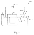
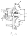
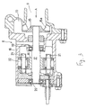
- FIGs. 1 to 4 are drawings showing the cooling water circulating apparatus of a mode of embodiment of the present invention, wherein Fig. 1 is a system diagram of a cooling water circulating apparatus 1, Fig. 2 a sectional view of a first water pump, Fig. 3 a sectional view of a second water pump, and Fig. 4 a characteristic diagram of the second water pump.
- the cooling water circulating apparatus 1 is an apparatus for circulating cooling water through an engine 2 and a radiator 3, and provided with a first water pump 4 which has a first supply port 5 for supplying cooling water flowing through the engine 2, and a first discharge port 6 for discharging the supplied cooling water to the engine 2 again, and which is connected to and rotated with a cam shaft 2A (two-dot chain lines in Fig.
- a thermostat 7 as a control mechanism adapted to cut off a flow of the cooling water which is supplied from the radiator 3 to the first supply port 5 when the temperature of the cooling water is not higher than a predetermined level, and communicate the radiator 3 and first supply port 5 when the temperature of the cooling water is higher than a predetermined level
- a second water pump 8 which has a second supply port 9 for supplying the cooling water flowing through the interior of the engine 2, and a second discharge port 10 for discharging the supplied cooling water toward the first supply port 5 of the first water pump 4, and which is not rotated when the temperature of the cooling water is not higher than a predetermined level, and rotated electrically when the temperature of the cooling water is higher than a predetermined level, the cooling water being circulated through the interior of the radiator 3 in accordance with the temperature of the cooling water.
- the first water pump 4 is formed of a driving shaft 11 rotated with the cam shaft 2A, a rotor 12 mounted on a free end portion of the driving shaft 11, first supply port 5 for supplying the cooling water therefrom, and the first discharge port 6 for discharging the supplied cooling water to the engine 2, and this water pump 4 is rotated with the same rotational frequency as the cam shaft 2A, i.e., with a rotational frequency 1/2 of that of the crankshaft.
- the second water pump 8 is a DC brushless motor provided with a metal rotor 15 for sucking and discharging the cooling water, a rotary shaft 17 which has the rotor 15 mounted fixedly on a free end portion thereof, and which is rotated with the rotor 15, a housing 18 fixed to the engine 2, bearings 19, 20 supporting the rotary shaft 17 on the housing 18 so that the rotary shaft 17 can be rotated relatively to the housing 18, a magnet 16 formed on an outer circumferential surface of the rotary shaft 17, cores 21 arranged on an inner circumference of the housing 18, and a plurality of coils 22 wound around each core 21 and forming a magnetic circuit with the magnet 16.
- the second water pump 8 is formed so that, when an electric current flows in the coils 22, the rotary shaft 17 is rotated with the magnet 16 with the rotor 15 also rotated, whereby the cooling water flowing from the second supply port 9 is discharged from the second discharge port 10.
- the rotational frequency of the rotor 15 can be varied arbitrarily within the volume of the pump in accordance with the level of the electric current flowing in the coils 22.
- a CPU (not shown) rotates the second water pump 8 by controlling the electric current, which flows in the coils 22, in accordance with the temperature of the cooling water.
- the second discharge port 10 is formed so as to deviate from the center of rotation of the rotor 15, and blades 15a of the rotor 15 so as to extend radially with respect to the mentioned center of rotation.
- the direction of rotation of the rotary shaft 17 is switched by changing the direction of the electric current flowing in the coils 22.
- a hot water type heater 23 is provided between the engine 2 and second supply port 9, and the warmed cooling water is subjected to heat exchange in the heater 23, a blower (not shown) being operated to warm the interior of a vehicle. Since the second water pump 8 is electrically driven, the rotational frequency can be controlled with a high accuracy, and a flow rate of the cooling water sent to the heater 23 is secured, so that the performance of the heater is improved.
- the thermostat 7 is a wax type thermostat adapted to switch the circulation and cut off of the cooling water, which is sent from the radiator 3 to the first water pump 4, from one to the other by utilizing the expansion and contraction, which occur in accordance with the temperature, of thermowax.
- the operation of the cooling water circulating apparatus 1 will be described.
- the engine 2 is started to cause the driving shaft 11 and the rotor 12 of the first water pump 4 to be rotated in accordance with the rotation of the cam shaft 2A, the cooling water is supplied from the first supply port 5 owing to pumping actions of the first water pump 4, and the supplied cooling water is discharged toward the first discharge port 6.
- the cooling water When the temperature of the cooling water during a cooling operation is lower than a predetermined level, the cooling water is not circulated in the radiator 3 so as to rapidly warm the engine 2. In this case, the thermostat 7 is closed to cut off a flow of the cooling water from the radiator 3 to the first supply port 5. The second water pump 8 is not rotated. During this time, the cooling water is discharged from the first discharge port 6 of the first water pump 4 into the interior of the engine 2, and flows in the interior of the engine 2 and then into the supply 9 port of the second water pump 8 via the heater 23.
- the cooling water flows from the second supply port 9 into the second discharge port 10, and then into the first supply port 5 of the first water pump 4, and the cooling water is thereafter discharged from the first discharge port 6 owing to the pumping actions.
- the cooling water discharged from the first discharge port 6 flows in the interior of the engine 2, and then returns to the first supply port 5 via the thermostat 7, the resultant cooling water being then circulated in the interior of the engine 2 again. This operation is repeated until the temperature of the cooling water reaches a predetermined level.
- the thermostat 7 is opened, and the radiator 3 and first supply port 5 communicate with each other, so that the cooling water cooled in the radiator 3 is supplied to the first water pump 4 with the cooling water circulated through the engine 2.
- the cooling water flowing through the interior of the engine 2 and warmed is sent to the heater 23, and then passes through the second supply port 9 of the second water pump 8, the resultant cooling water being discharged from the second discharge port 10 thereof.
- the cooling water is then supplied to the first supply port 5 of the first water pump 4, and to the interior of the engine 2 again.
- the cooling water cooled by the radiator 3 and heater 23 is supplied to the engine 2, and the temperature of the water in the engine 2 is thereby maintained at a suitable level. Since the second water pump 8 is driven when the temperature of the cooling water attains a level not lower than a predetermined level, the pump head of the cooling water circulating apparatus 1 as a whole becomes equal to the sum of the pump head of the first water pump 4 and that of the second water pump 8, and a flow rate of the cooling water to the engine 2 and radiator 3 is secured.
- using the electrically driven second water pump 8 makes it possible to secure a flow rate of the cooling water circulated through the radiator 3 and engine 2, without increasing the head of the first water pump 4 rotated with the cam shaft 2A. This enables the fuel consumption to be improved.
- the second discharge port 10 of the second water pump 8 is formed so as to deviate from the center of rotation of the rotor 15, and the blades 15a of the rotor 15 so as to extend radially with respect to the same center of rotation. Accordingly, it becomes possible to control the flow of the cooling water by rotating the rotor 15 both forward and backward.
- the cooling water flows, from the second water pump 8 to the first water pump 4 without passing through the thermostat 7 when the cooling water flowing out from the engine 2 is sent to the first water pump 4. Therefore, the thermostat 7 can be formed so that the cooling water flowing out from the engine 2 is not supplied thereto. This enables one of the valves of the thermostat 7 to be omitted, and the resistance of the cooling water exerted on the thermostat 7 to be lowered, whereby the durability of the thermostat 7 is improved.
- the electrically driven second water pump when the cooling water is circulated through both the engine and radiator, the electrically driven second water pump is rotated, whereby the circulation of the cooling water is carried out at a required flow rate. Therefore, when the driving of the first water pump alone causes a discharge rate of the cooling water to become short, the second water pump is rotated to enable the shortage of the discharge rate to be filled up. Owing to this operation, a suitable quantity of cooling water can always be circulated. Since the second water pump is electrically driven, the rotational frequency can be controlled, and the flow rate of the cooling water can also be arbitrarily regulated.
- the cooling water is circulated at a required flow rate through both the engine and radiator by rotating the electrically driven second water pump. Therefore, it becomes possible to secure a required flow rate of the cooling water without increasing the dimensions of the first water pump even when the first water pump is driven with the cam shaft, this invention thus proving to be preferable.
- the present invention provides a cooling water circulating apparatus capable of securing a required flow rate of cooling water without increasing the heads of water pumps, the apparatus including a first water pump which has a first supply port for supplying thereinto cooling water which is to flow through the interior of an engine, and a first discharge port for discharging therefrom the supplied cooling water to the engine again, and which is connected to and rotated with a cam shaft of the engine, a control mechanism adapted to cut off a flow of the cooling water, which is directed from a radiator to the first supply port, when the temperature of the cooling water is not higher than a predetermined level, and communicate the radiator and first supply port with each other when the temperature of the cooling water is higher than the predetermined level, and a second water pump which has a second supply port for supplying thereinto cooling water which is to flow through the interior of the engine, and a second discharge port for discharging therefrom the supplied cooling water to the supply port of the first water pump, and which is not rotated when the temperature of the cooling water is not higher than a
Landscapes
- Engineering & Computer Science (AREA)
- Chemical & Material Sciences (AREA)
- Combustion & Propulsion (AREA)
- Mechanical Engineering (AREA)
- General Engineering & Computer Science (AREA)
- Structures Of Non-Positive Displacement Pumps (AREA)
Claims (5)
- Appareil de circulation d'eau de refroidissement adapté pour faire circuler l'eau de refroidissement à travers un moteur (2) ou un radiateur (3) comprenant :une première pompe à eau (4) qui comporte un premier orifice d'alimentation pour alimenter dans celle-ci l'eau de refroidissement qui doit circuler à travers l'intérieur du moteur, et d'un premier orifice de décharge connecté pour décharger de celle-ci l'eau de refroidissement délivrée au moteur (2) de nouveau, et qui est connectée et mise en rotation avec un arbre à cames du moteur (2),un mécanisme de commande (7) adapté pour couper un écoulement de l'eau de refroidissement, qui est dirigé depuis un radiateur (3) vers le premier orifice d'alimentation, lorsque la température de l'eau de refroidissement n'est pas plus élevée qu'un niveau prédéterminé, et pour faire communiquer le radiateur (3) etle premier orifice d'alimentation l'un avec l'autre lorsque la température de l'eau de refroidissement est plus élevée que le niveau prédéterminé, etune seconde pompe à eau (8) qui comporte un second orifice d'alimentation pour délivrer dans celle-ci l'eau de refroidissement qui doit s'écouler à travers l'intérieure du moteur, et un second orifice de décharge connecté pour décharger de celle-ci l'eau de refroidissement délivrée à l'orifice d'alimentation de la première pompe à eau (4) et qui est une seconde pompe à eau de mise en rotation électriquement en conformité avec la température de l'eau de refroidissement.
- Appareil de circulation de l'eau de refroidissement selon la revendication 1, dans lequel la seconde pompe à eau n'est pas mise en rotation lorsque la température de l'eau de refroidissement n'est pas plus élevée que le niveau prédéterminé, et mise en rotation électriquement lorsque la température de l'eau de refroidissement est plus élevée que le niveau prédéterminé.
- Appareil de circulation de l'eau de refroidissement selon la revendication 1, dans lequel un dispositif de chauffage est disposé entre le moteur et le second orifice d'alimentation de la seconde pompe à eau.
- Appareil de circulation de l'eau de refroidissement selon la revendication 1, dans lequel les pales d'un rotor de la seconde pompe à eau sont formées de façon à s'étendre radialement par rapport au centre de rotation du rotor, la direction de rotation du rotor étant apte à être commuter d'une direction avant à une direction arrière, et vice versa. 5. Appareil de circulation de l'eau de refroidissement selon la revendication 4, dans lequel le second orifice de décharge de la seconde pompe à eau est formé dans cette partie qui dévie du centre de rotation de son rotor.
Applications Claiming Priority (2)
| Application Number | Priority Date | Filing Date | Title |
|---|---|---|---|
| JP10360998A JP2000179339A (ja) | 1998-12-18 | 1998-12-18 | 冷却水循環装置 |
| JP36099898 | 1998-12-18 |
Publications (3)
| Publication Number | Publication Date |
|---|---|
| EP1010873A2 EP1010873A2 (fr) | 2000-06-21 |
| EP1010873A3 EP1010873A3 (fr) | 2002-03-20 |
| EP1010873B1 true EP1010873B1 (fr) | 2005-05-11 |
Family
ID=18471766
Family Applications (1)
| Application Number | Title | Priority Date | Filing Date |
|---|---|---|---|
| EP99125269A Expired - Lifetime EP1010873B1 (fr) | 1998-12-18 | 1999-12-17 | Appareil de circulation pour l'eau de refroidissement |
Country Status (4)
| Country | Link |
|---|---|
| US (1) | US6247429B1 (fr) |
| EP (1) | EP1010873B1 (fr) |
| JP (1) | JP2000179339A (fr) |
| DE (1) | DE69925232T2 (fr) |
Families Citing this family (31)
| Publication number | Priority date | Publication date | Assignee | Title |
|---|---|---|---|---|
| US6739290B2 (en) * | 2001-03-06 | 2004-05-25 | Calsonic Kansei Corporation | Cooling system for water-cooled internal combustion engine and control method applicable to cooling system therefor |
| US8540493B2 (en) | 2003-12-08 | 2013-09-24 | Sta-Rite Industries, Llc | Pump control system and method |
| US7131825B2 (en) * | 2004-01-30 | 2006-11-07 | Isothermal Systems Research, Inc. | Spindle-motor driven pump system |
| EP1585205B1 (fr) * | 2004-04-09 | 2017-12-06 | Regal Beloit America, Inc. | Système de pompage et procédé pour détecter le blocage du système de pompage |
| US20080095639A1 (en) * | 2006-10-13 | 2008-04-24 | A.O. Smith Corporation | Controller for a motor and a method of controlling the motor |
| US8133034B2 (en) * | 2004-04-09 | 2012-03-13 | Regal Beloit Epc Inc. | Controller for a motor and a method of controlling the motor |
| US8602745B2 (en) | 2004-08-26 | 2013-12-10 | Pentair Water Pool And Spa, Inc. | Anti-entrapment and anti-dead head function |
| US7854597B2 (en) | 2004-08-26 | 2010-12-21 | Pentair Water Pool And Spa, Inc. | Pumping system with two way communication |
| US8480373B2 (en) | 2004-08-26 | 2013-07-09 | Pentair Water Pool And Spa, Inc. | Filter loading |
| US7686589B2 (en) | 2004-08-26 | 2010-03-30 | Pentair Water Pool And Spa, Inc. | Pumping system with power optimization |
| US7845913B2 (en) | 2004-08-26 | 2010-12-07 | Pentair Water Pool And Spa, Inc. | Flow control |
| US8469675B2 (en) | 2004-08-26 | 2013-06-25 | Pentair Water Pool And Spa, Inc. | Priming protection |
| US8019479B2 (en) | 2004-08-26 | 2011-09-13 | Pentair Water Pool And Spa, Inc. | Control algorithm of variable speed pumping system |
| US7874808B2 (en) | 2004-08-26 | 2011-01-25 | Pentair Water Pool And Spa, Inc. | Variable speed pumping system and method |
| US20080095638A1 (en) * | 2006-10-13 | 2008-04-24 | A.O. Smith Corporation | Controller for a motor and a method of controlling the motor |
| US7690897B2 (en) * | 2006-10-13 | 2010-04-06 | A.O. Smith Corporation | Controller for a motor and a method of controlling the motor |
| DE102008007285A1 (de) * | 2008-02-02 | 2009-08-06 | Bayerische Motoren Werke Aktiengesellschaft | Nockenwellengetriebene Pumpe für eine Kraftfahrzeug-Brennkraftmaschine und Kraftfahrzeug-Brennkraftmaschine |
| DE102008024532A1 (de) * | 2008-05-21 | 2009-11-26 | Bayerische Motoren Werke Aktiengesellschaft | Kupplungseinrichtung |
| US7673591B2 (en) * | 2008-06-10 | 2010-03-09 | Deere & Company | Nucleate boiling cooling system and method |
| AU2009298834B2 (en) | 2008-10-01 | 2015-07-16 | Regal Beloit America, Inc. | Controller for a motor and a method of controlling the motor |
| EP3418570B1 (fr) | 2008-10-06 | 2020-01-22 | Pentair Water Pool and Spa, Inc. | Procédé d'actionnement d'un système brise-vide de sécurité |
| US8869756B2 (en) | 2008-12-10 | 2014-10-28 | Ford Global Technologies, Llc | Cooling system and method for a vehicle engine |
| US9556874B2 (en) | 2009-06-09 | 2017-01-31 | Pentair Flow Technologies, Llc | Method of controlling a pump and motor |
| US8327812B2 (en) * | 2009-07-24 | 2012-12-11 | Deere & Company | Nucleate boiling cooling system |
| BR112013014476A2 (pt) | 2010-12-08 | 2016-09-20 | Pentair Water Pool & Spa Inc | válvula de descarga de alívio de vácuo para um sistema de segurança de liberação de vácuo |
| WO2013067206A1 (fr) | 2011-11-01 | 2013-05-10 | Pentair Water Pool And Spa, Inc. | Système et procédé de blocage de débit |
| US9360015B2 (en) | 2012-07-16 | 2016-06-07 | Magna Powertrain Of America, Inc. | Submerged rotor electric water pump with structural wetsleeve |
| US9885360B2 (en) | 2012-10-25 | 2018-02-06 | Pentair Flow Technologies, Llc | Battery backup sump pump systems and methods |
| US9611781B2 (en) * | 2015-01-09 | 2017-04-04 | GM Global Technology Operations LLC | System and method of thermal management for an engine |
| JP6581129B2 (ja) * | 2017-02-14 | 2019-09-25 | トヨタ自動車株式会社 | 内燃機関の冷却装置 |
| US10450941B2 (en) * | 2018-01-31 | 2019-10-22 | Ford Global Technologies, Llc | Engine cooling system and method |
Family Cites Families (7)
| Publication number | Priority date | Publication date | Assignee | Title |
|---|---|---|---|---|
| DE2408508C3 (de) * | 1974-02-22 | 1979-02-22 | Sueddeutsche Kuehlerfabrik Julius Fr. Behr Gmbh & Co Kg, 7000 Stuttgart | Vorrichtung zur wasserseitigen Temperaturregelung, insbesondere von Kraftfahrzeugheizungs- und Klimaanlagen |
| JPS56165713A (en) * | 1980-05-21 | 1981-12-19 | Toyota Motor Corp | Cooler for engine |
| JPS611819A (ja) * | 1984-05-10 | 1986-01-07 | Honda Motor Co Ltd | 水冷式内燃機関における水ポンプの駆動装置 |
| US4768484A (en) * | 1987-07-13 | 1988-09-06 | General Motors Corporation | Actively pressurized engine cooling system |
| JP2767995B2 (ja) * | 1989-12-28 | 1998-06-25 | 株式会社デンソー | 内燃機関の冷却装置 |
| JP3208295B2 (ja) | 1995-09-26 | 2001-09-10 | ダイハツ工業株式会社 | 内燃機関の冷却装置 |
| JPH11303635A (ja) * | 1998-04-23 | 1999-11-02 | Aisin Seiki Co Ltd | エンジンの冷却装置 |
-
1998
- 1998-12-18 JP JP10360998A patent/JP2000179339A/ja active Pending
-
1999
- 1999-12-17 DE DE69925232T patent/DE69925232T2/de not_active Expired - Lifetime
- 1999-12-17 EP EP99125269A patent/EP1010873B1/fr not_active Expired - Lifetime
- 1999-12-20 US US09/466,775 patent/US6247429B1/en not_active Expired - Lifetime
Also Published As
| Publication number | Publication date |
|---|---|
| US6247429B1 (en) | 2001-06-19 |
| JP2000179339A (ja) | 2000-06-27 |
| EP1010873A2 (fr) | 2000-06-21 |
| DE69925232D1 (de) | 2005-06-16 |
| DE69925232T2 (de) | 2006-02-23 |
| EP1010873A3 (fr) | 2002-03-20 |
Similar Documents
| Publication | Publication Date | Title |
|---|---|---|
| US6247429B1 (en) | Cooling water circulating apparatus | |
| JPH0444084B2 (fr) | ||
| CN101363354A (zh) | 用于内燃机的冷却泵和使用该冷却泵的冷却系统 | |
| US20040031451A1 (en) | Method and apparatus for regulating the operating temperature of an internal combustion engine | |
| JP4215276B2 (ja) | 自動車用クーラントポンプ | |
| US6199528B1 (en) | Cooling device for internal combustion engines | |
| JP3438211B2 (ja) | 内燃機関のウォータポンプ | |
| EP0921284A2 (fr) | Perfectionnements aux moteurs à combustion interne refroidis par liquide | |
| JP5242785B2 (ja) | 可変流量式ポンプ | |
| JP2006022644A (ja) | 流体送り装置及びこの流体送り装置を使用したタイヤ加硫装置 | |
| JP2002106347A (ja) | 内燃機関の冷却水温制御装置 | |
| US6199518B1 (en) | Cooling device of an engine | |
| KR102027834B1 (ko) | 전자식 워터펌프 | |
| KR101131487B1 (ko) | 차량용 워터펌프 | |
| JP3557683B2 (ja) | 車両用冷却水温度制御システム | |
| JP2002130190A (ja) | 電動ウォータポンプ装置 | |
| JPH09275664A (ja) | モータ制御システム | |
| KR20050061626A (ko) | 엔진의 냉각수 분배장치 | |
| JPH09158724A (ja) | 車両用循環水路構造 | |
| JP4879408B2 (ja) | 軸流ポンプ | |
| JPH0417715A (ja) | 内燃機関の冷却装置 | |
| JP2002188443A (ja) | 内燃機関の冷却装置 | |
| JPH1191344A (ja) | ウォータポンプ一体型剪断発熱器 | |
| GB2332046A (en) | I.C engine cooling system | |
| JP2023074371A (ja) | 内燃システム |
Legal Events
| Date | Code | Title | Description |
|---|---|---|---|
| PUAI | Public reference made under article 153(3) epc to a published international application that has entered the european phase |
Free format text: ORIGINAL CODE: 0009012 |
|
| AK | Designated contracting states |
Kind code of ref document: A2 Designated state(s): AT BE CH CY DE DK ES FI FR GB GR IE IT LI LU MC NL PT SE Kind code of ref document: A2 Designated state(s): DE FR GB |
|
| AX | Request for extension of the european patent |
Free format text: AL;LT;LV;MK;RO;SI |
|
| PUAL | Search report despatched |
Free format text: ORIGINAL CODE: 0009013 |
|
| AK | Designated contracting states |
Kind code of ref document: A3 Designated state(s): AT BE CH CY DE DK ES FI FR GB GR IE IT LI LU MC NL PT SE |
|
| AX | Request for extension of the european patent |
Free format text: AL;LT;LV;MK;RO;SI |
|
| 17P | Request for examination filed |
Effective date: 20020424 |
|
| AKX | Designation fees paid |
Free format text: DE FR GB |
|
| GRAJ | Information related to disapproval of communication of intention to grant by the applicant or resumption of examination proceedings by the epo deleted |
Free format text: ORIGINAL CODE: EPIDOSDIGR1 |
|
| GRAP | Despatch of communication of intention to grant a patent |
Free format text: ORIGINAL CODE: EPIDOSNIGR1 |
|
| GRAP | Despatch of communication of intention to grant a patent |
Free format text: ORIGINAL CODE: EPIDOSNIGR1 |
|
| GRAS | Grant fee paid |
Free format text: ORIGINAL CODE: EPIDOSNIGR3 |
|
| GRAA | (expected) grant |
Free format text: ORIGINAL CODE: 0009210 |
|
| RIN1 | Information on inventor provided before grant (corrected) |
Inventor name: OZAWA, YASUO Inventor name: HARA, NAOHIRO |
|
| AK | Designated contracting states |
Kind code of ref document: B1 Designated state(s): DE FR GB |
|
| REG | Reference to a national code |
Ref country code: GB Ref legal event code: FG4D |
|
| REG | Reference to a national code |
Ref country code: IE Ref legal event code: FG4D |
|
| REF | Corresponds to: |
Ref document number: 69925232 Country of ref document: DE Date of ref document: 20050616 Kind code of ref document: P |
|
| ET | Fr: translation filed | ||
| PLBE | No opposition filed within time limit |
Free format text: ORIGINAL CODE: 0009261 |
|
| STAA | Information on the status of an ep patent application or granted ep patent |
Free format text: STATUS: NO OPPOSITION FILED WITHIN TIME LIMIT |
|
| 26N | No opposition filed |
Effective date: 20060214 |
|
| REG | Reference to a national code |
Ref country code: GB Ref legal event code: 746 Effective date: 20091016 |
|
| PGFP | Annual fee paid to national office [announced via postgrant information from national office to epo] |
Ref country code: GB Payment date: 20091216 Year of fee payment: 11 Ref country code: FR Payment date: 20091221 Year of fee payment: 11 |
|
| PGFP | Annual fee paid to national office [announced via postgrant information from national office to epo] |
Ref country code: DE Payment date: 20091222 Year of fee payment: 11 |
|
| GBPC | Gb: european patent ceased through non-payment of renewal fee |
Effective date: 20101217 |
|
| REG | Reference to a national code |
Ref country code: FR Ref legal event code: ST Effective date: 20110831 |
|
| PG25 | Lapsed in a contracting state [announced via postgrant information from national office to epo] |
Ref country code: FR Free format text: LAPSE BECAUSE OF NON-PAYMENT OF DUE FEES Effective date: 20110103 |
|
| REG | Reference to a national code |
Ref country code: DE Ref legal event code: R119 Ref document number: 69925232 Country of ref document: DE Effective date: 20110701 |
|
| PG25 | Lapsed in a contracting state [announced via postgrant information from national office to epo] |
Ref country code: DE Free format text: LAPSE BECAUSE OF NON-PAYMENT OF DUE FEES Effective date: 20110701 Ref country code: GB Free format text: LAPSE BECAUSE OF NON-PAYMENT OF DUE FEES Effective date: 20101217 |