EP1010952A2 - Verfahren zur Steuerung der Richtung des Luftstromes in einer Klimaanlage - Google Patents
Verfahren zur Steuerung der Richtung des Luftstromes in einer Klimaanlage Download PDFInfo
- Publication number
- EP1010952A2 EP1010952A2 EP99124106A EP99124106A EP1010952A2 EP 1010952 A2 EP1010952 A2 EP 1010952A2 EP 99124106 A EP99124106 A EP 99124106A EP 99124106 A EP99124106 A EP 99124106A EP 1010952 A2 EP1010952 A2 EP 1010952A2
- Authority
- EP
- European Patent Office
- Prior art keywords
- air
- temperature
- air conditioner
- direction changing
- changing blade
- Prior art date
- Legal status (The legal status is an assumption and is not a legal conclusion. Google has not performed a legal analysis and makes no representation as to the accuracy of the status listed.)
- Granted
Links
Images


Classifications
-
- F—MECHANICAL ENGINEERING; LIGHTING; HEATING; WEAPONS; BLASTING
- F24—HEATING; RANGES; VENTILATING
- F24F—AIR-CONDITIONING; AIR-HUMIDIFICATION; VENTILATION; USE OF AIR CURRENTS FOR SCREENING
- F24F1/00—Room units for air-conditioning, e.g. separate or self-contained units or units receiving primary air from a central station
- F24F1/0007—Indoor units, e.g. fan coil units
- F24F1/0011—Indoor units, e.g. fan coil units characterised by air outlets
-
- F—MECHANICAL ENGINEERING; LIGHTING; HEATING; WEAPONS; BLASTING
- F24—HEATING; RANGES; VENTILATING
- F24F—AIR-CONDITIONING; AIR-HUMIDIFICATION; VENTILATION; USE OF AIR CURRENTS FOR SCREENING
- F24F1/00—Room units for air-conditioning, e.g. separate or self-contained units or units receiving primary air from a central station
- F24F1/0007—Indoor units, e.g. fan coil units
- F24F1/0043—Indoor units, e.g. fan coil units characterised by mounting arrangements
- F24F1/0057—Indoor units, e.g. fan coil units characterised by mounting arrangements mounted in or on a wall
Definitions
- the present invention relates generally to control of an air conditioner and, in particular but not exclusively, to an air direction control method for controlling the air direction or the air flow during dehumidifying mode operation to increase the degree of dehumidification or to improve a feeling of coolness.
- dehumidified air is introduced indoors through an air direction changing blade directed downwards that is mounted on an indoor unit.
- an air conditioner employing a short-circuit system wherein cool air emitted from an air outlet of an indoor unit is directly drawn into an air inlet by setting the air direction changing blade upwards.
- This air conditioner aims to achieve comfortable dehumidification without any feeling of chilliness by causing the cool air not to directly impinge on the residents (see, for example, Japanese Laid-Open Patent Publication No. 9-72599).
- this air conditioner almost eliminates the feeling of chilliness during dehumidifying mode operation, the amount of moisture that is removed thereby is relatively little and the dehumidifying efficiency thereof is low, resulting in a relatively high ultimate humidity.
- the present invention has been developed to overcome the above-described disadvantages.
- the air conditioner according to the present invention includes an outdoor unit having a variable capacity compressor, a four-way valve, an outdoor heat exchanger, and an expansion valve, and an indoor unit having an indoor heat exchanger and connected with the outdoor unit.
- the indoor unit also has an air direction changing blade pivotally mounted thereon for selectively opening and closing an outlet opening defined therein.
- the air direction changing blade is set to a closed position, at which the outlet opening is closed, or a position adjacent thereto during dehumidifying mode operation.
- an indoor fan mounted in the indoor unit be set to a medium air flow or below when the air direction changing blade is set to the closed position or the position adjacent thereto, making it possible to eliminate the feeling of chilliness.
- the indoor fan is set to a minimum air flow and is turned on and off. By so doing, no drops of dew are created around an outlet opening of the indoor unit during dehumidification.
- variable capacity compressor is reduced in frequency, resulting in a reduction in input.
- cooling mode operation is performed, thereby accomplishing effective dehumidification and preventing drops of dew from being created around the outlet opening when it is closed. Furthermore, the use of both the cooling mode operation and the dehumidifying mode operation enlarges the range of use, making it possible to efficiently operate the air conditioner.
- the indoor fan is reduced in air flow and the variable capacity compressor is increased in frequency.
- the air direction changing blade is set to the closed position or the position adjacent thereto. In this case, it is unlikely that drops of dew adhere to the indoor unit in the vicinity of the outlet opening and subsequently fall to the floor, thus making it possible to desirably perform the dehumidifying mode operation during closure of the outlet opening.
- the humidity setting is changed according to at least one of the intake temperature and the pipe temperature.
- the air direction changing blade is set to the closed position or the position adjacent thereto, thereby avoiding creation of drops of dew around the outlet opening.
- the predetermined temperature is changed according to the intake temperature.
- the angle of inclination of the air direction changing blade is held for a predetermined time, thereby avoiding chattering of the air direction changing blade.
- the indoor unit can be stably controlled by determining a target pipe temperature according to the detected intake temperature and the detected humidity.
- the opening of the expansion valve is reduced, or the frequency of the variable capacity compressor is increased.
- the opening of the expansion valve is increased, or the frequency of the variable capacity compressor is reduced.
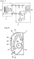
- Fig. 1 shows a refrigeration cycle of an air conditioner employing an air direction control method according to the present invention.
- This air conditioner includes an outdoor unit 2 and an indoor unit 4 connected to each other via connecting pipes 6.
- the outdoor unit 2 includes an inverter-driven, variable capacity (frequency) compressor 8, a four-way valve 10 for heating and cooling mode selection, an outdoor heat exchanger 12, an auxiliary throttle 14, and a motor-driven expansion valve 16, while the indoor unit 4 includes an indoor heat exchanger 18.
- reference numerals 20 and 22 denote an outdoor fan and an indoor fan, respectively
- reference numerals 24, 26 and 28 denote a pipe temperature sensor, an intake air temperature sensor, and a humidity sensor, respectively, all of which are mounted in the indoor unit 4.
- refrigerant from the compressor 8 during cooling or dehumidifying mode operation flows through the four-way valve 10 and reaches the outdoor heat exchanger 12, in which heat is exchanged with the outdoor air and the refrigerant is condensed.
- the condensed refrigerant then passes the auxiliary throttle 14 whereby the refrigerant pressure is reduced and the refrigerant is converted to an easily evaporable state.
- the condensed, low pressure refrigerant then passes the motor-driven expansion valve 16 whereby the refrigerant pressure is further reduced.
- the opening of the motor-driven expansion valve 16 is pulse-controlled by, for example, a stepping-motor according to the load of the room to be cooled or dehumidified, and the low pressure refrigerant thus flows to the indoor unit 4 via the connecting pipe 6 at a flow rate proportional to the load of the room.
- the refrigerant then evaporates in the indoor heat exchanger 18, and the gasified refrigerant thus passes back through the connecting pipe 6, through the four-way valve 10, and re-enters the compressor 8.
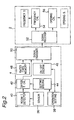
- differential temperature ⁇ T is the room temperature Tr minus the temperature setting Ts.
- an output (room temperature) from the intake air temperature sensor 26 is first inputted into a room temperature detection circuit 40, which in turn outputs a temperature signal (Tr) to a differential temperature calculator 42.
- a setting discriminator 44 determines the temperature (Ts) and operating mode set by an operation setting circuit 38, and supplies this information to the differential temperature calculator 42.
- An ON/OFF discriminator 46 determines whether the indoor unit 4 has been turned on or off.
- the rated capacity of the indoor unit 4 is stored in a rated capacity memory 48.
- a rated capacity signal from the rated capacity memory 48, the differential temperature signal from the differential temperature calculator 42, and an operating mode signal and on/off status signal from the ON/OFF discriminator 46 are passed by the signal transmission circuit 50 of the indoor unit 4 to a signal reception circuit 52 of the outdoor unit 2.
- the signals received by the signal reception circuit 52 are sent to a compressor frequency calculator 54 and to a valve opening calculator 56.
- the compressor frequency calculator 54 Based on the rated capacity signal, differential temperature signal, operating mode signal, and on/off status signal from the indoor unit 4, the compressor frequency calculator 54 performs a predetermined operation to calculate the frequency value (No.) (for example, an integer from 0 to 8).
- valve opening calculator 56 Based on the rated capacity signal, differential temperature signal, operating mode signal, and on/off status signal from the indoor unit 4, the valve opening calculator 56 similarly performs another predetermined operation to determine the opening of the motor-driven expansion valve 16.
- the result of the operation performed by the compressor frequency calculator 54 and that of the operation performed by the valve opening calculator 56 are applied as a frequency signal and a valve opening signal to a compressor drive circuit (not shown) and to a valve drive circuit (not shown), respectively, to control the frequency of the compressor 8 and the opening of the motor-driven expansion valve 16.
- the frequency No. of the compressor 8 and the valve opening of the motor-driven expansion valve 16 are calculated for each predetermined cycle, based on the rated capacity signal, differential temperature signal, operating mode signal, and on/off status signal so that the frequency of the compressor 8 and the opening of the motor-driven expansion valve 16 may be appropriately controlled.
- a heating mode operation is not a principal objective of the present invention and, hence, the description thereof is omitted.
- Fig. 3 depicts the indoor unit 4, in which a plurality of intake openings 30 are formed at an upper portion and a front portion of the main body, while an outlet opening 32 is formed at a lower portion of the main body.
- the intake openings 30 and the outlet opening 32 communicate with each other through an air passage 34, in which the indoor heat exchanger 18 and the indoor fan 22 are disposed.
- An air direction changing blade 36 is pivotally mounted on the main body at a lower portion thereof so as to selectively open and close the outlet opening 32.
- the pipe temperature sensor 24 is mounted on and held in contact with a lowermost one of a plurality of heat exchanger blocks of the indoor heat exchanger 18, while the intake air temperature sensor 26 and the humidity sensor 28 are juxtaposed with each other at a front portion of the main body.
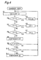
- Fig. 4 depicts the control method during the dehumidifying mode operation.
- the differential temperature ⁇ T between the room temperature detected by the intake air temperature sensor 26 and the temperature setting Ts set by the user is first calculated, and the compressor frequency and the valve opening are then determined on the basis of the differential temperature ⁇ T, as described above.
- the differential temperature ⁇ T is compared with t1 (for example, +0.5°C). If the differential temperature ⁇ T is greater than t1, a cooling mode operation is performed at step S3, and if the differential temperature ⁇ T is less than or equal to t1, the procedure advances to step S4, at which the differential temperature ⁇ T is compared with t2 (for example, -0.5°C).
- step S5 If the differential temperature ⁇ T is greater than t2, an operation for "Drying Region 1" is performed at step S5. In contrast, if the differential temperature ⁇ T is less than or equal to t2, the procedure advances to step S6, at which the differential temperature ⁇ T is compared with t3 (for example, -2.5°C). If the differential temperature ⁇ T is greater than t3, an operation for "Drying Region 2" is performed at step S7, and if the differential temperature ⁇ T is less than or equal to t3, the compressor 8 is stopped at step S8. A determination is then made at step S9 whether or not a predetermined time t4 (for example, about three minutes) has elapsed after the compressor 8 has been stopped. If the decision at step S9 is YES, the differential temperature ⁇ T is again compared with T3 at step S10. If the differential temperature ⁇ T is greater than t3, the compressor 8 is started again at step S11.
- t4 for example, about three minutes
- the sampling of the intake air temperature is carried out for each predetermined cycle (for example, about one second), and the operating conditions are determined by repeatedly calculating the differential temperature ⁇ T.
- the air direction changing blade 36 swings between the upper limit position and the lower limit position, as shown in Fig. 5, except when the indoor fan 22 is at a standstill. It is also possible for the user to set the angle of inclination of the air direction changing blade 36 to one of five different angles with the use of the remote controller.
- the compressor frequency is extremely reduced (the Frequency No. is, for example, 1), while the indoor fan 22 is set to an air flow ranging from "Hi (high speed)" to "Lo (low speed)".
- the frequency No. of the compressor 8 is set to, for example, 3, while the indoor fan 22 is set to a medium air flow or "Super Breeze” lower than “Lo". If “Air Direction-Auto” is set, the air direction changing blade 36 is directed generally horizontally, as shown in Fig. 6, to reduce the feeling of chilliness. On the other hand, if “Air Direction Setting” is selected, it is possible for the user to select one of five different angles of inclination of the air direction changing blade 36 using the remote controller, as in the cooling operation in the dehumidification mode.
- the frequency No. of the compressor 8 is set to, for example, 2, while either a “Super Breeze and Dry” operation or a “Breezeless and Dry " operation is set depending on the operating conditions, as discussed later.
- the indoor fan 22 creates a light or gentle breeze to provide an extremely low air flow and is turned on and off.
- the air direction changing blade 36 is set to a position (this position is hereinafter referred to as the downwards directed position) directed further downwards from the lower limit position in the operation for "Drying Region 1", thus causing cold or chilly air not to directly impinge on the resident or residents.
- the "Air Direction Selling” it is possible for the user to set the air direction changing blade 36 to one of five different positions between the upper limit position and the downwards directed position using the remote controller.
- the ON/OFF operation of the indoor fan 22 is, for example, such that the indoor fan 22 is turned on and off to repeat a 15-minute operation and a 10-minute stop alternately.
- the indoor fan 22 creates a light or gentle breeze to provide an extremely low air flow
- the air direction changing blade 36 is set to a position (reset position) to close the outlet opening 32 or another position in the vicinity thereof.
- the "Breezeless and Dry” operation is carried out when the decision at step S6 is YES and when any one of the conditions shown in Table 1 is continued for, for example, more than five minutes in "Drying Region 2" (step S7).
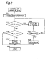
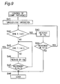
- step S21 After any one of the "Breezeless” conditions has been satisfied and after the air direction changing blade 36 has been held at the reset position or a position in the vicinity thereof for a predetermined time (for example, about five minutes), a determination is made at step S21 whether or not the pipe temperature detected by the pipe temperature sensor 24 is less than (the target pipe temperature (A) minus three). If the decision at step S21 is YES, the "Breezeless and Dry" operation is immediately terminated at step S22, and if the decision at step S21 is No, the procedure advances to step S23, at which a determination is made whether or not the pipe temperature is less than (the target pipe temperature (A) minus two).
- step S23 If the decision at step S23 is YES, the "Breezeless and Dry” operation is continued for thirty minutes and stopped thereafter at step S24. In contrast, if the decision at step S23 is NO, the procedure advances to step S25, at which the "Breezeless and Dry” operation is continued for sixty minutes and stopped thereafter.
- the target pipe temperature (A) is determined based on Table 2 below using the intake air temperature detected by the intake air temperature sensor 26 and the relative humidity detected by the humidity sensor 28.
- the procedure returns to step S32, and if the valve opening is less than the set minimum pulses, it is set to the set minimum pulses at step S35.
- the detected pipe temperature is less than or equal to (the target pipe temperature (A) plus one) at step S32, a determination is made at step S36 whether or not the detected pipe temperature is greater than (the target pipe temperature (A) minus one). If the detected pipe temperature is less than or equal to (the target pipe temperature (A) minus one), the motor-driven expansion valve 16 is controlled to be opened by, for example, eight pulses at step S37. In contrast, if the detected pipe temperature is greater than (the target pipe temperature (A) minus one), the motor-driven expansion valve 16 is locked to the present opening at step S38.
- step S42 If the increment in compressor frequency is less than 5Hz, the procedure returns to step S42 after a predetermined time (for example, about three minutes) has elapsed, and if the increment is greater than or equal to 5Hz, the procedure advances to step S48 at which the frequency 8 is locked to the present frequency.
- a predetermined time for example, about three minutes
- the procedure advances to step S48 at which the frequency 8 is locked to the present frequency.
- the detected pipe temperature is less than or equal to (the target pipe temperature (A) plus one) at step S42, a determination is made at step S45 whether or not the detected pipe temperature is greater than (the target pipe temperature (A) minus one).
- step S46 the frequency of the compressor 8 is reduced by 1Hz at step S46, and the procedure advances to step S47 at which a determination is made whether or not a decrement in compressor frequency is less than 5Hz. If the decrement in compressor frequency is less than 5Hz, the procedure returns to step S45 after a predetermined time (for example, about three minutes) has elapsed. In contrast, if the decrement is greater than or equal to 5Hz, the compressor 8 is locked to the present frequency at step S48. On the other hand, if the detected pipe temperature is greater than (the target pipe temperature (A) minus one) at step S45, the procedure advances to step S48 at which the compressor 8 is similarly locked to the present frequency.
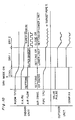
- Fig. 10 depicts one example of timing charts when the air direction control method according to the present invention has been employed.
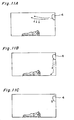
- Figs. 11A, 11B and 11C depict cool air flows during dehumidifying mode operation when the air direction control method according to the present invention has been employed.
- Fig. 11A depicts the cool air flow in "Drying Region 1" when "Air Direction-Auto” has been set
- Fig. 11B the cool air flow in "Drying Region 2" when the indoor fan is turned on and off
- Fig. 11C the cool air flow in "Drying Region 2" during “Breezeless and Dry” operation.
Landscapes
- Engineering & Computer Science (AREA)
- Chemical & Material Sciences (AREA)
- Combustion & Propulsion (AREA)
- Mechanical Engineering (AREA)
- General Engineering & Computer Science (AREA)
- Air Conditioning Control Device (AREA)
- Air-Flow Control Members (AREA)
Applications Claiming Priority (2)
| Application Number | Priority Date | Filing Date | Title |
|---|---|---|---|
| JP35419598 | 1998-12-14 | ||
| JP10354195A JP3011708B1 (ja) | 1998-12-14 | 1998-12-14 | 空気調和機の風向制御方法 |
Publications (3)
| Publication Number | Publication Date |
|---|---|
| EP1010952A2 true EP1010952A2 (de) | 2000-06-21 |
| EP1010952A3 EP1010952A3 (de) | 2002-05-02 |
| EP1010952B1 EP1010952B1 (de) | 2004-06-16 |
Family
ID=18435931
Family Applications (1)
| Application Number | Title | Priority Date | Filing Date |
|---|---|---|---|
| EP99124106A Expired - Lifetime EP1010952B1 (de) | 1998-12-14 | 1999-12-02 | Verfahren zur Steuerung der Richtung des Luftstromes in einer Klimaanlage |
Country Status (5)
| Country | Link |
|---|---|
| EP (1) | EP1010952B1 (de) |
| JP (1) | JP3011708B1 (de) |
| CN (1) | CN1114073C (de) |
| ES (1) | ES2222652T3 (de) |
| MY (1) | MY123346A (de) |
Cited By (2)
| Publication number | Priority date | Publication date | Assignee | Title |
|---|---|---|---|---|
| US10962249B2 (en) | 2018-03-20 | 2021-03-30 | Panasonic Intellectual Property Management Co., Ltd. | Air conditioning apparatus and air conditioning control method |
| CN112648695A (zh) * | 2020-12-29 | 2021-04-13 | 明德倍适(天津)科技有限公司 | 辐射空调系统及温湿度调节方法 |
Families Citing this family (11)
| Publication number | Priority date | Publication date | Assignee | Title |
|---|---|---|---|---|
| KR100434069B1 (ko) * | 2001-08-01 | 2004-06-04 | 엘지전자 주식회사 | 공기조화기의 제습운전방법 |
| CN101542210B (zh) * | 2006-12-05 | 2011-06-08 | 大金工业株式会社 | 空调机的室内机 |
| JP2009236482A (ja) * | 2008-02-05 | 2009-10-15 | Daikin Ind Ltd | 空気調和機 |
| JP5336931B2 (ja) * | 2009-05-27 | 2013-11-06 | パナソニック株式会社 | 空気調和機 |
| TWI427247B (zh) * | 2011-06-24 | 2014-02-21 | Univ Nat Pingtung Sci & Tech | 可控制進排氣之通風系統 |
| CN103383126B (zh) * | 2012-05-04 | 2016-03-02 | 珠海格力电器股份有限公司 | 分体挂壁式空调器导风板的控制方法 |
| CN105444335B (zh) * | 2014-08-21 | 2020-06-26 | 广东美的集团芜湖制冷设备有限公司 | 空调器的控制方法、空调器的控制装置和空调器 |
| CN105241017B (zh) * | 2015-10-26 | 2018-11-06 | 广东美的制冷设备有限公司 | 空调系统及空调压缩机的频率控制方法 |
| JP2019163920A (ja) * | 2018-03-20 | 2019-09-26 | パナソニックIpマネジメント株式会社 | 空気調和装置及び空調制御方法 |
| CN110617528A (zh) * | 2019-09-25 | 2019-12-27 | 佛山市顺德区美的洗涤电器制造有限公司 | 控制方法、厨房电器及存储介质 |
| WO2024023916A1 (ja) * | 2022-07-26 | 2024-02-01 | 三菱電機株式会社 | 空気調和機 |
Citations (2)
| Publication number | Priority date | Publication date | Assignee | Title |
|---|---|---|---|---|
| JPH0972599A (ja) | 1995-06-28 | 1997-03-18 | Toshiba Ave Corp | 空気調和機 |
| JPH1061999A (ja) | 1996-08-23 | 1998-03-06 | Mitsubishi Electric Corp | 空気調和機用室内機の風向制御方法 |
Family Cites Families (3)
| Publication number | Priority date | Publication date | Assignee | Title |
|---|---|---|---|---|
| US5678417A (en) * | 1995-06-28 | 1997-10-21 | Kabushiki Kaisha Toshiba | Air conditioning apparatus having dehumidifying operation function |
| EP0819894B1 (de) * | 1996-06-26 | 2004-10-06 | Kabushiki Kaisha Toshiba | Innenraumeinheit für eine Klimaanlage |
| JPH1096525A (ja) * | 1996-09-20 | 1998-04-14 | Fujitsu General Ltd | 空気調和機 |
-
1998
- 1998-12-14 JP JP10354195A patent/JP3011708B1/ja not_active Expired - Lifetime
-
1999
- 1999-12-02 ES ES99124106T patent/ES2222652T3/es not_active Expired - Lifetime
- 1999-12-02 EP EP99124106A patent/EP1010952B1/de not_active Expired - Lifetime
- 1999-12-10 MY MYPI99005387A patent/MY123346A/en unknown
- 1999-12-14 CN CN99126969A patent/CN1114073C/zh not_active Expired - Fee Related
Patent Citations (2)
| Publication number | Priority date | Publication date | Assignee | Title |
|---|---|---|---|---|
| JPH0972599A (ja) | 1995-06-28 | 1997-03-18 | Toshiba Ave Corp | 空気調和機 |
| JPH1061999A (ja) | 1996-08-23 | 1998-03-06 | Mitsubishi Electric Corp | 空気調和機用室内機の風向制御方法 |
Cited By (2)
| Publication number | Priority date | Publication date | Assignee | Title |
|---|---|---|---|---|
| US10962249B2 (en) | 2018-03-20 | 2021-03-30 | Panasonic Intellectual Property Management Co., Ltd. | Air conditioning apparatus and air conditioning control method |
| CN112648695A (zh) * | 2020-12-29 | 2021-04-13 | 明德倍适(天津)科技有限公司 | 辐射空调系统及温湿度调节方法 |
Also Published As
| Publication number | Publication date |
|---|---|
| EP1010952B1 (de) | 2004-06-16 |
| ES2222652T3 (es) | 2005-02-01 |
| CN1114073C (zh) | 2003-07-09 |
| EP1010952A3 (de) | 2002-05-02 |
| JP2000179916A (ja) | 2000-06-30 |
| CN1263236A (zh) | 2000-08-16 |
| MY123346A (en) | 2006-05-31 |
| JP3011708B1 (ja) | 2000-02-21 |
Similar Documents
| Publication | Publication Date | Title |
|---|---|---|
| JP3137114B1 (ja) | 多室形空気調和装置 | |
| JP4957342B2 (ja) | 空気調和システム及び空調管理装置 | |
| EP1010952B1 (de) | Verfahren zur Steuerung der Richtung des Luftstromes in einer Klimaanlage | |
| JP2018059702A (ja) | 空気調和機 | |
| JP2006317142A (ja) | 天井型エアコンのベーン制御方法 | |
| CN109237704B (zh) | 用于多联机空调系统的控制方法 | |
| JPH1061998A (ja) | 空気調和機 | |
| JP3223918B2 (ja) | 多室形空気調和システム | |
| JPH0755234A (ja) | 空気調和装置 | |
| JP2697282B2 (ja) | 空気調和機 | |
| JP2012007887A (ja) | 空気調和システム及び空調管理装置 | |
| JPH09138012A (ja) | 空気調和機 | |
| JP2697281B2 (ja) | 空気調和機の制御装置 | |
| JPH07158937A (ja) | 冷凍サイクル制御装置 | |
| JPH0328673A (ja) | 蓄熱式空気調和装置 | |
| JPH05322275A (ja) | 多室形空気調和システム | |
| JP2720594B2 (ja) | 空気調和機 | |
| JP2720595B2 (ja) | 空気調和機 | |
| JPH08276720A (ja) | 車両用空気調和装置 | |
| JP3378712B2 (ja) | 空気調和機 | |
| JPH07280324A (ja) | 温度湿度制御装置 | |
| JPH0285647A (ja) | 空気調和機 | |
| JPH10185280A (ja) | 空気調和装置 | |
| JP2672638B2 (ja) | 空気調和機の除湿装置 | |
| JP2003176943A (ja) | 空気調和機 |
Legal Events
| Date | Code | Title | Description |
|---|---|---|---|
| PUAI | Public reference made under article 153(3) epc to a published international application that has entered the european phase |
Free format text: ORIGINAL CODE: 0009012 |
|
| AK | Designated contracting states |
Kind code of ref document: A2 Designated state(s): AT BE CH CY DE DK ES FI FR GB GR IE IT LI LU MC NL PT SE Kind code of ref document: A2 Designated state(s): ES GR IT |
|
| AX | Request for extension of the european patent |
Free format text: AL;LT;LV;MK;RO;SI |
|
| PUAL | Search report despatched |
Free format text: ORIGINAL CODE: 0009013 |
|
| RIC1 | Information provided on ipc code assigned before grant |
Free format text: 7F 24F 11/00 A, 7F 24F 1/00 B, 7F 24F 3/14 B |
|
| AK | Designated contracting states |
Kind code of ref document: A3 Designated state(s): AT BE CH CY DE DK ES FI FR GB GR IE IT LI LU MC NL PT SE |
|
| AX | Request for extension of the european patent |
Free format text: AL;LT;LV;MK;RO;SI |
|
| 17P | Request for examination filed |
Effective date: 20021104 |
|
| AKX | Designation fees paid |
Free format text: ES GR IT |
|
| REG | Reference to a national code |
Ref country code: DE Ref legal event code: 8566 |
|
| GRAP | Despatch of communication of intention to grant a patent |
Free format text: ORIGINAL CODE: EPIDOSNIGR1 |
|
| GRAS | Grant fee paid |
Free format text: ORIGINAL CODE: EPIDOSNIGR3 |
|
| GRAA | (expected) grant |
Free format text: ORIGINAL CODE: 0009210 |
|
| AK | Designated contracting states |
Kind code of ref document: B1 Designated state(s): ES GR IT |
|
| REG | Reference to a national code |
Ref country code: IE Ref legal event code: FG4D |
|
| REG | Reference to a national code |
Ref country code: GR Ref legal event code: EP Ref document number: 20040402941 Country of ref document: GR |
|
| REG | Reference to a national code |
Ref country code: ES Ref legal event code: FG2A Ref document number: 2222652 Country of ref document: ES Kind code of ref document: T3 |
|
| PLBE | No opposition filed within time limit |
Free format text: ORIGINAL CODE: 0009261 |
|
| STAA | Information on the status of an ep patent application or granted ep patent |
Free format text: STATUS: NO OPPOSITION FILED WITHIN TIME LIMIT |
|
| 26N | No opposition filed |
Effective date: 20050317 |
|
| PGFP | Annual fee paid to national office [announced via postgrant information from national office to epo] |
Ref country code: IT Payment date: 20081224 Year of fee payment: 10 |
|
| PGFP | Annual fee paid to national office [announced via postgrant information from national office to epo] |
Ref country code: GR Payment date: 20081120 Year of fee payment: 10 |
|
| PG25 | Lapsed in a contracting state [announced via postgrant information from national office to epo] |
Ref country code: IT Free format text: LAPSE BECAUSE OF NON-PAYMENT OF DUE FEES Effective date: 20091202 |
|
| PGFP | Annual fee paid to national office [announced via postgrant information from national office to epo] |
Ref country code: ES Payment date: 20131112 Year of fee payment: 15 |
|
| REG | Reference to a national code |
Ref country code: ES Ref legal event code: FD2A Effective date: 20160205 |
|
| PG25 | Lapsed in a contracting state [announced via postgrant information from national office to epo] |
Ref country code: ES Free format text: LAPSE BECAUSE OF NON-PAYMENT OF DUE FEES Effective date: 20141203 |