EP1013922A2 - Hochdruckkraftstoffpumpe mit verändlicher Durchflussmenge - Google Patents
Hochdruckkraftstoffpumpe mit verändlicher Durchflussmenge Download PDFInfo
- Publication number
- EP1013922A2 EP1013922A2 EP99310601A EP99310601A EP1013922A2 EP 1013922 A2 EP1013922 A2 EP 1013922A2 EP 99310601 A EP99310601 A EP 99310601A EP 99310601 A EP99310601 A EP 99310601A EP 1013922 A2 EP1013922 A2 EP 1013922A2
- Authority
- EP
- European Patent Office
- Prior art keywords
- valve
- fuel
- inlet port
- pump
- chamber
- Prior art date
- Legal status (The legal status is an assumption and is not a legal conclusion. Google has not performed a legal analysis and makes no representation as to the accuracy of the status listed.)
- Granted
Links
- 239000000446 fuel Substances 0.000 title claims abstract description 204
- 239000012530 fluid Substances 0.000 claims abstract description 11
- 238000004891 communication Methods 0.000 claims abstract description 10
- 230000000903 blocking effect Effects 0.000 claims description 3
- 230000009471 action Effects 0.000 abstract description 6
- 230000001105 regulatory effect Effects 0.000 abstract description 2
- 230000006835 compression Effects 0.000 description 8
- 238000007906 compression Methods 0.000 description 8
- 230000033001 locomotion Effects 0.000 description 7
- 230000001276 controlling effect Effects 0.000 description 4
- 238000002347 injection Methods 0.000 description 4
- 239000007924 injection Substances 0.000 description 4
- 230000007246 mechanism Effects 0.000 description 4
- 230000004048 modification Effects 0.000 description 4
- 238000012986 modification Methods 0.000 description 4
- 238000002485 combustion reaction Methods 0.000 description 3
- 230000003111 delayed effect Effects 0.000 description 3
- 230000003466 anti-cipated effect Effects 0.000 description 2
- 238000007789 sealing Methods 0.000 description 2
- 239000007921 spray Substances 0.000 description 2
- 206010035148 Plague Diseases 0.000 description 1
- 241000607479 Yersinia pestis Species 0.000 description 1
- 230000005540 biological transmission Effects 0.000 description 1
- 230000008859 change Effects 0.000 description 1
- 239000002131 composite material Substances 0.000 description 1
- 238000013016 damping Methods 0.000 description 1
- 230000003292 diminished effect Effects 0.000 description 1
- 230000000694 effects Effects 0.000 description 1
- 230000008030 elimination Effects 0.000 description 1
- 238000003379 elimination reaction Methods 0.000 description 1
- 230000002349 favourable effect Effects 0.000 description 1
- 239000002828 fuel tank Substances 0.000 description 1
- 239000010687 lubricating oil Substances 0.000 description 1
- 238000004519 manufacturing process Methods 0.000 description 1
- 230000007935 neutral effect Effects 0.000 description 1
- 238000005086 pumping Methods 0.000 description 1
- 230000009467 reduction Effects 0.000 description 1
- 230000004044 response Effects 0.000 description 1
- 230000000630 rising effect Effects 0.000 description 1
- 238000004804 winding Methods 0.000 description 1
Images


Classifications
-
- F—MECHANICAL ENGINEERING; LIGHTING; HEATING; WEAPONS; BLASTING
- F04—POSITIVE - DISPLACEMENT MACHINES FOR LIQUIDS; PUMPS FOR LIQUIDS OR ELASTIC FLUIDS
- F04B—POSITIVE-DISPLACEMENT MACHINES FOR LIQUIDS; PUMPS
- F04B49/00—Control, e.g. of pump delivery, or pump pressure of, or safety measures for, machines, pumps, or pumping installations, not otherwise provided for, or of interest apart from, groups F04B1/00 - F04B47/00
- F04B49/22—Control, e.g. of pump delivery, or pump pressure of, or safety measures for, machines, pumps, or pumping installations, not otherwise provided for, or of interest apart from, groups F04B1/00 - F04B47/00 by means of valves
- F04B49/225—Control, e.g. of pump delivery, or pump pressure of, or safety measures for, machines, pumps, or pumping installations, not otherwise provided for, or of interest apart from, groups F04B1/00 - F04B47/00 by means of valves with throttling valves or valves varying the pump inlet opening or the outlet opening
-
- F—MECHANICAL ENGINEERING; LIGHTING; HEATING; WEAPONS; BLASTING
- F02—COMBUSTION ENGINES; HOT-GAS OR COMBUSTION-PRODUCT ENGINE PLANTS
- F02M—SUPPLYING COMBUSTION ENGINES IN GENERAL WITH COMBUSTIBLE MIXTURES OR CONSTITUENTS THEREOF
- F02M59/00—Pumps specially adapted for fuel-injection and not provided for in groups F02M39/00 -F02M57/00, e.g. rotary cylinder-block type of pumps
- F02M59/02—Pumps specially adapted for fuel-injection and not provided for in groups F02M39/00 -F02M57/00, e.g. rotary cylinder-block type of pumps of reciprocating-piston or reciprocating-cylinder type
- F02M59/10—Pumps specially adapted for fuel-injection and not provided for in groups F02M39/00 -F02M57/00, e.g. rotary cylinder-block type of pumps of reciprocating-piston or reciprocating-cylinder type characterised by the piston-drive
- F02M59/102—Mechanical drive, e.g. tappets or cams
-
- F—MECHANICAL ENGINEERING; LIGHTING; HEATING; WEAPONS; BLASTING
- F02—COMBUSTION ENGINES; HOT-GAS OR COMBUSTION-PRODUCT ENGINE PLANTS
- F02M—SUPPLYING COMBUSTION ENGINES IN GENERAL WITH COMBUSTIBLE MIXTURES OR CONSTITUENTS THEREOF
- F02M59/00—Pumps specially adapted for fuel-injection and not provided for in groups F02M39/00 -F02M57/00, e.g. rotary cylinder-block type of pumps
- F02M59/20—Varying fuel delivery in quantity or timing
- F02M59/36—Varying fuel delivery in quantity or timing by variably-timed valves controlling fuel passages to pumping elements or overflow passages
- F02M59/366—Valves being actuated electrically
-
- F—MECHANICAL ENGINEERING; LIGHTING; HEATING; WEAPONS; BLASTING
- F02—COMBUSTION ENGINES; HOT-GAS OR COMBUSTION-PRODUCT ENGINE PLANTS
- F02M—SUPPLYING COMBUSTION ENGINES IN GENERAL WITH COMBUSTIBLE MIXTURES OR CONSTITUENTS THEREOF
- F02M59/00—Pumps specially adapted for fuel-injection and not provided for in groups F02M39/00 -F02M57/00, e.g. rotary cylinder-block type of pumps
- F02M59/44—Details, components parts, or accessories not provided for in, or of interest apart from, the apparatus of groups F02M59/02 - F02M59/42; Pumps having transducers, e.g. to measure displacement of pump rack or piston
- F02M59/46—Valves
- F02M59/466—Electrically operated valves, e.g. using electromagnetic or piezoelectric operating means
-
- F—MECHANICAL ENGINEERING; LIGHTING; HEATING; WEAPONS; BLASTING
- F02—COMBUSTION ENGINES; HOT-GAS OR COMBUSTION-PRODUCT ENGINE PLANTS
- F02M—SUPPLYING COMBUSTION ENGINES IN GENERAL WITH COMBUSTIBLE MIXTURES OR CONSTITUENTS THEREOF
- F02M63/00—Other fuel-injection apparatus having pertinent characteristics not provided for in groups F02M39/00 - F02M57/00 or F02M67/00; Details, component parts, or accessories of fuel-injection apparatus, not provided for in, or of interest apart from, the apparatus of groups F02M39/00 - F02M61/00 or F02M67/00; Combination of fuel pump with other devices, e.g. lubricating oil pump
- F02M63/0012—Valves
- F02M63/0014—Valves characterised by the valve actuating means
- F02M63/0028—Valves characterised by the valve actuating means hydraulic
- F02M63/0029—Valves characterised by the valve actuating means hydraulic using a pilot valve controlling a hydraulic chamber
-
- F—MECHANICAL ENGINEERING; LIGHTING; HEATING; WEAPONS; BLASTING
- F04—POSITIVE - DISPLACEMENT MACHINES FOR LIQUIDS; PUMPS FOR LIQUIDS OR ELASTIC FLUIDS
- F04B—POSITIVE-DISPLACEMENT MACHINES FOR LIQUIDS; PUMPS
- F04B7/00—Piston machines or pumps characterised by having positively-driven valving
- F04B7/0076—Piston machines or pumps characterised by having positively-driven valving the members being actuated by electro-magnetic means
-
- Y—GENERAL TAGGING OF NEW TECHNOLOGICAL DEVELOPMENTS; GENERAL TAGGING OF CROSS-SECTIONAL TECHNOLOGIES SPANNING OVER SEVERAL SECTIONS OF THE IPC; TECHNICAL SUBJECTS COVERED BY FORMER USPC CROSS-REFERENCE ART COLLECTIONS [XRACs] AND DIGESTS
- Y10—TECHNICAL SUBJECTS COVERED BY FORMER USPC
- Y10T—TECHNICAL SUBJECTS COVERED BY FORMER US CLASSIFICATION
- Y10T137/00—Fluid handling
- Y10T137/8593—Systems
- Y10T137/87917—Flow path with serial valves and/or closures
- Y10T137/88046—Biased valve with external operator
-
- Y—GENERAL TAGGING OF NEW TECHNOLOGICAL DEVELOPMENTS; GENERAL TAGGING OF CROSS-SECTIONAL TECHNOLOGIES SPANNING OVER SEVERAL SECTIONS OF THE IPC; TECHNICAL SUBJECTS COVERED BY FORMER USPC CROSS-REFERENCE ART COLLECTIONS [XRACs] AND DIGESTS
- Y10—TECHNICAL SUBJECTS COVERED BY FORMER USPC
- Y10T—TECHNICAL SUBJECTS COVERED BY FORMER US CLASSIFICATION
- Y10T137/00—Fluid handling
- Y10T137/8593—Systems
- Y10T137/87917—Flow path with serial valves and/or closures
- Y10T137/88054—Direct response normally closed valve limits direction of flow
Definitions
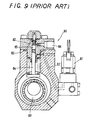
- variable-delivery high-pressure fuel pumps For the variable-delivery high-pressure fuel pumps, generally, two types of pumps have been developed one of that is a high-pressure fuel pump 80 of inlet port-metering system, as shown in FIG. 9. It has an inlet port valve 81 for regulating an inflow rate of fuel into a cylinder to control a metered amount of fuel discharged.
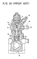
- the other is a high-pressure fuel pump 90 of a system that is termed pre-stroke control, as shown in FIG. 10, where an inlet port valve 91 is controlled according to the pre-stroke way.
- a piston section of the main valve body moves in a reciprocating manner in compliance with the combination of an urging force of a main valve spring and a pressure difference between the back-pressure chamber and an area in a main valve chamber, which communicates with a fuel passage or is exposed to the pump chamber, to thereby let the main valve body open and close between the back-pressure chamber and the subsidiary valve chamber.
- No fuel in the pump chamber is discharged backwards to the fuel passage at an earlier portion of lift of the plunger.
- Energization of the solenoid-actuated valve nevertheless, regulates the timing for closure of the main valve body that allows the pressure to escape from the back-pressure chamber. This controls the effective stroke of the plunger after the back-pressure chamber has been disconnected from the pump chamber in a compressively forcing phase of the plunger.
- the present invention is concerned with a variable-delivery high-pressure fuel pump comprising, a pump chamber varying in volume as a plunger moves in and out, an inlet port valve forming at a one end thereof a part of chamber walls of the pump chamber, the inlet port valve being opened when a low-pressure fuel is admitted into the pump chamber from a fuel inlet passage, while being closed when the admitted fuel is delivered out of the pump chamber, a control chamber defined on an opposing end of the inlet port valve to receive therein the low-pressure fuel applied through the fuel inlet passage, and a control valve for intermittently opening and blocking a fluid communication between the control chamber and the fuel inlet passage.
- the control valve In the event the fuel in the pump chamber is flowing backwards into the fuel inlet passage according to the upward movement of the plunger, the instant the control valve is opened, the inlet port valve is relieved from the pressure acting in the direction to open the inlet port valve and, thus moved to its closure position. With the inlet port valve coming in closure, the fuel pressure in the pump chamber is elevated up to a high pressure. Thereafter, the fuel pressure in the pump chamber begins to rise and the fuel intensified in fuel pressure is delivered out of the pump chamber, past the fuel delivery line during the delivery stroke of the plunger. Control of the timing the control valve is made open results in controlling the timing for closure of the inlet port valve to thereby regulate the amount of fuel delivered out of the pump chamber.
- a variable-delivery high-pressure fuel pump which regulates a timing for opening the control valve as the plunger moves from bottom dead center to top dead center of its stroke, to thereby control a timing for closure of the inlet port valve, resulting in metering an amount of fuel delivered out of the pump chamber.
- Control of the timing a signal to energize the control valve is turned off results in controlling the timing the position of the control valve causes the control chamber to open, that is, the timing the inlet port valve is made closed off and at the same time the fuel delivery out of the pump chamber begins.
- Possible control of the timing the fuel delivery begins makes it possible to meter the amount of fuel delivered out of the pump chamber per very delivery cycle of the fuel pump.
- the high-pressure fuel pump of the present invention constructed as described above makes the inlet port valve open and close by the effect of low-pressure fuel applied from the fuel-supply pump. Only the control valve is, thus, sufficient to regulate the fuel supply of low-pressure fuel to the control chamber and the fuel relief out of the control chamber. As a result, smaller equivalent size of the control valve is realized with the reduction of noise on operation as well as the less consumption of electric power. Moreover, because of smaller equivalent size, it may become possible to make easy mount the fuel pump on the engine, according to the modification as to the arrangement of the fuel pump.
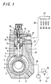
- the high-pressure fuel pump 1 has a pump housing 2 where a camshaft 3 is supported for rotation.
- the camshaft 3 is driven from a crankshaft of an engine through suitable power transmissions such as belt drives.
- the camshaft 3 has thereon a cam 4, around the periphery of which a rotary ring 6 is fitted for rotation through bearings 5.
- the cam 4, bearings 6 and rotary ring 6 are all accommodated in a cam chamber 7 in the pump housing 2.
- a plunger 10 is arranged in a bore 8 in the pump housing 2 for linear reciprocating movement and urged against the rotary ring 6 by the elastic action of a plunger return spring 9.
- the plunger 10 terminates at its one end in tappet 11, which comes at its one surface in engagement with one end of the plunger return spring 9 while at the opposite surface in abutment with the rotary ring 6.
- the plunger return spring 9 urges elastically the tappet 11 against the rotary ring 6.
- a barrel 12 is mounted on a top surface of the pump housing 2 and provided therein with a barrel bore 13 in which the plunger 10 fits for sliding movement.
- the barrel 12 is further made at an upper area thereof with a discharge port 14 extending sideways, where a delivery valve 15 of a check valve is arranged.
- the plunger 10 is accommodated for reciprocating movement in the barrel bore 13 of the barrel 12 in such a manner as to provide a pump chamber 16, which is defined in the upper area of the barrel bore 13 on the top of the plunger 10.
- Fuel is delivered at a low pressure to a fuel line 20 from a fuel-supply pump 17 and then charged in a fuel reservoir 24, formed on the top surface of the pump housing 2, through a fuel passage 21 formed in the pump housing 2, an annular channel 22 formed at an interface of the pump housing 2 with the barrel 12, and a fuel inlet passage 23 extending upwardly through the pump housing 2 from the annular channel 22.
- the fuel line 20 branches to a by-pass line in which a relief valve 18 is arranged so that a fuel pressure over a preselected pressure level may be returned to a fuel tank 19 via the relief valve 18.
- the fuel reservoir 24 is communicated with the pump chamber 16 through an inlet port valve 30, as will be described in detail hereinafter.
- the discharge port 14 is made with threads at 25, to which a fuel-delivery line 25 is coupled to lead the delivered fuel to a common fuel-rail 27.
- the fuel is intensified in pressure in the pump chamber 16 up to a high fuel-pressure, where the pressurized fuel forces the delivery valve 15 opening to thereby reach the common fuel-rail 27 through the fuel-delivery line 26.
- the high-pressure fuel may be applied to injectors 28 from the common fuel-rail 27.
- the fuel leaking out the pump chamber 30 through around the plunger 10 is recovered via a drain port 29, with being separated from lubricating oil.
- the barrel 12 is provided with the inlet port valve 30 to intermittently open and block a fluid communication between the pump chamber 16 and the fuel reservoir 24, and a control valve 50 to operate the inlet port valve 30. Combination of the inlet port valve 30 with the control valve 50 will be described below in conjunction with FIG. 2.
- the inlet port valve 30 has a valve head 31 arranged in the pump chamber 16, and a valve stem 32 extending out of the barrel 12 into the control valve 50. At closure event of the inlet port valve 30, a valve face 33 of the valve head 31 comes in abutment with a valve seat 34 to block the pump chamber 16 from the fuel reservoir 24.
- the valve stem 32 extends through a hole 35 in the barrel 12, with keeping an annular clearance 36 around the valve stem 34.
- the valve stem 34 slide-fits in a guide hole 38 of a cylindrical bushing 37. It will be noted that the bushing 37 also has a function as a lower seat to bear a return spring 41 for the inlet port valve 30.
- a snap ring 39 is fitted around the upper portion of the valve stem 32 while a spring guide 40, also serving as a spring bearing, is fitted on the valve stem 32.
- the snap ring 39 comes in engagement with the spring guide 40 to be kept against linear motion relatively of the valve stem 32.
- a compression spring 41 acting on the inlet port valve 30 is arranged between the bushing 31 and the compression spring 41 under compressed condition. As a result, the compression spring 41 urges forcibly the inlet port valve 30 towards its closure position, where the valve head 31 come in fluid-tight contact with its valve seal 34 to isolate reliably the pump chamber 16.
- a valve cap 42 is mounted on the barrel 12 to shield fluid-tightly the fuel reservoir 24 through a sealing ring.
- valve cap 42 is made therein with a central recess 43, where the valve stem 32 is received at the upper portion thereof.
- the valve stem 32 fits snugly at its top end 48 in a bore 44 in the valve cap 42, following passing through the guide hole 38 in the bushing 37, whereby the valve stem 32 may be ensured against becoming off-centre or eccentric, which might be otherwise happen due to the hydraulic pressure boosted in the pump chamber 16 when the plunger 10 lifts or moves in.
- the armature 53 Upon energizing the solenoid 52, the armature 53 is forced to move downwards against the resilient force of the return spring 54 and, thus, the valvular portion 55 blocks the open end of the small passage 47, with resulting in keeping the control chamber 45 at a fluid-tightly isolated condition.
- the solenoid 52 When the solenoid 52 is deenergized, the armature 53 lifts by the action of the return spring 54 to open the small passage 47, through which the control chamber 45 is allowed to communicate with the low-pressure side.
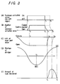
- the pressurized fuel in the pump chamber 16 cannot be tolerated to open the delivery valve 15 leading to the fuel-delivery line 26, but may flow backwards to the low-pressure side such as the fuel inlet passage 23, fuel reservoir 24 and the like via the still-opened inlet port valve 30.
- the relief valve 18 works to return the tank 19 the amount of fuel equivalent with the fuel, which has flowed backwards to the low-pressure side such as the fuel inlet passage 23.
- the fuel in the pump chamber 16 starts to cease from flowing backwards to the low-pressure side, and the resultant pressurized fuel in the pump chamber 16 is delivered beginning to the fuel delivery line 26 through the delivery valve 15.
- the pressurized fuel in the pump chamber 16 continues delivered to the fuel delivery line 26 till the instant t 7 the plunger 10 reaches the top dead center of its stroke.
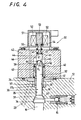
- variable-delivery high-pressure fuel pump will be described with reference to FIG. 4. Except for the structure of the control chamber, this second embodiment of the variable-delivery high-pressure fuel pump shown in FIG. 4 is substantially identical in most components thereof, compared with the variable-delivery high-pressure fuel pump in FIGS. 1 and 2. Thus, the like reference numerals designate the components or parts identical or equivalent with that used in the variable-delivery high-pressure fuel pump in FIGS. 1 and 2, so that the previous description will be applicable.
- variable-delivery high-pressure fuel pump in FIGS. 1 and 2 has the control chamber defined in the bore 44 of the valve cap 42 on the top end 48 of the valve stem 32 of the inlet port valve 30, which fits in the bore 44, whereas the second embodiment has a control chamber 45 defined in the bore 44 of the valve cap 42 on a top face 61 an intermediate piston 60, which fits in the bore 44.
- the intermediate piston 60 is a component separately from the valve stem 32 of the inlet port valve 30 and comes in abutment with the upper end of the valve stem 32 of the inlet port valve 30.
- a spring member 63 Arranged in the control chamber 45 is a spring member 63 coming in engagement with the intermediate piston 60 to urge the piston 60 towards the valve stem 32 of the inlet port valve 30. As long as the reliable operation of the intermediate piston 60 is ensured, no spring member 63 may be necessary.
- the compression spring 41 or an inlet valve spring, is arranged under compression between the bushing 37, acting as a lower spring seat, and the spring guide 40 locked against falling off from the inlet port valve 30 by a snap ring 39, which is fitted on the upper area of the valve stem 32.
- Energization of the control valve 50 drives at high speed both the intermediate piston 60 and the valve stem 32 of the inlet port valve 30.
- the top face 64 of the valve stem 32 is formed in a convexity rising towards the intermediate piston 60, preferably in a part of a sphericity, while the bottom face 62 of the intermediate piston 60, confronting the valve stem 32 of the inlet port valve 30, is formed in a concavity, preferably in a part of a sphericity.
- the bottom face 62 on the intermediate piston 60 should be designed larger in the radius of concave curvature R 2 compared with the radius of convex curvature R 1 of the top face 64 of the valve stem 32.
- This design as to the radii of curvature on the confronting faces of the intermediate piston 60 and the valve stem 32 helps ensure the concentric alignment of the valve stem 32 with the intermediate piston 60, on either the event the intermediate piston 60 depresses the inlet port valve 30 along its centre axis or the reverse event the inlet port valve 30 lifts against the intermediate piston 60.
- this face-to-face abutment structure of the confronting curvatures contributes to keeping the valve stem 30 against off-centre from the intermediate piston 60, protecting the valve stem 32 against wobbling so that the inlet port valve 30 may operates with stability.
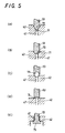
- FIGS. 5(A) to (E) show modified profiles of structures where the armature 53 of the control valve 50 opens and closes the small holes 47 of the control chamber.
- the armature 53 terminates in a needle-type valve head 70 that fits with a chamfered edge 71 at the open end of the small passage 47.
- the structure in FIG. 5(B) includes the armature 53 formed at the distal end thereof a round valve head 72, which fits with the chamfered edge 71 at the open end of the small passage 47.
- the armature 53 is mounted at the end thereof with a ball 73, which fits with the chamfered edge 71 at the open end of the small passage 47.
- FIG. 5(C) shows modified profiles of structures where the armature 53 of the control valve 50 opens and closes the small holes 47 of the control chamber.
- the armature 53 terminates in a needle-type valve head 70 that fits with a chamfered edge 71 at the open end of the small passage 47.
- 5(D) has the armature 53 terminating in a flat valve face 74, which comes in abutment with a raised open end of the small passage 47.
- the armature 53 terminates in poppet-type valve head 75 arranged in the control camber 45 so as to make contact with an open end of the small passage 47 inside the control chamber 45.
- control valve 50 is arranged just above the control chamber 45. Nevertheless, the embodied high-pressure fuel pumps are too tall in overall height to be snugly mounted as the pumps for fuel injection to the engine, which cannot be tolerated to provide a space enough in height. To reduce overall height of the fuel pump to make easy mount the fuel pump on the engine, it will be anticipated to arrange the control valve sideways the valve cap or modify the design of the control valve.
- FIG. 6 shows in section the essential parts of another embodiment of the variable-delivery high-pressure fuel pump, in which control valve 50 is arranged sideways of the valve cap 42.
- FIG. 7 there is shown in section the essential parts of another embodiment of the variable-delivery high-pressure fuel pump, in which a rotary valve is employed instead of the solenoid-actuated valve.
- FIG. 8 shows in section the essential parts of a further another embodiment of the variable-delivery high-pressure fuel pump, in which a spool valve is employed instead of the solenoid-operated valve.
- the like reference numerals designate the components or parts identical or equivalent in their function with that used in the embodiments having been described above, so that the previous description will be applicable.
- a small passage 100 to communicate the control chamber 45 with the low-pressure side extends sidewise from the control chamber 45.
- the valvular portion 55 of the control valve 50 moves in and out, thereby intermittently open and close the fluid communication between the path 46 and the small passage 100.
- FIG. 7 includes a rotary valve 102, which turns for intermittently opening and closing the fluid communication between the path 46 and the small passage 100.
- a spool valve 104 is provided which operates to open and close the fluid communication between the path 46 and the small passage 100.
Landscapes
- Engineering & Computer Science (AREA)
- Mechanical Engineering (AREA)
- General Engineering & Computer Science (AREA)
- Chemical & Material Sciences (AREA)
- Combustion & Propulsion (AREA)
- Physics & Mathematics (AREA)
- Electromagnetism (AREA)
- Fuel-Injection Apparatus (AREA)
Applications Claiming Priority (2)
| Application Number | Priority Date | Filing Date | Title |
|---|---|---|---|
| JP36794898 | 1998-12-24 | ||
| JP10367948A JP2000186649A (ja) | 1998-12-24 | 1998-12-24 | 吐出量可変制御型高圧燃料ポンプ |
Publications (3)
| Publication Number | Publication Date |
|---|---|
| EP1013922A2 true EP1013922A2 (de) | 2000-06-28 |
| EP1013922A3 EP1013922A3 (de) | 2003-05-07 |
| EP1013922B1 EP1013922B1 (de) | 2006-01-04 |
Family
ID=18490600
Family Applications (1)
| Application Number | Title | Priority Date | Filing Date |
|---|---|---|---|
| EP99310601A Expired - Lifetime EP1013922B1 (de) | 1998-12-24 | 1999-12-24 | Hochdruckkraftstoffpumpe mit verändlicher Durchflussmenge |
Country Status (4)
| Country | Link |
|---|---|
| US (1) | US6447273B1 (de) |
| EP (1) | EP1013922B1 (de) |
| JP (1) | JP2000186649A (de) |
| DE (1) | DE69929296T2 (de) |
Cited By (13)
| Publication number | Priority date | Publication date | Assignee | Title |
|---|---|---|---|---|
| US6640788B2 (en) | 2001-02-28 | 2003-11-04 | Denso Corporation | High pressure fuel pump |
| EP1701031A1 (de) * | 2005-03-11 | 2006-09-13 | Hitachi, Ltd. | Elektromagnetischer Antriebsmechanismus einer Hochdruck-Kraftstoffförderpumpe |
| WO2008005114A1 (en) * | 2006-06-29 | 2008-01-10 | Caterpillar Inc. | Inlet throttle controlled liquid pump with cavitation damage avoidance feature |
| WO2009058279A1 (en) * | 2007-10-31 | 2009-05-07 | Caterpillar Inc. | High-pressure pump |
| CN102003319A (zh) * | 2010-11-19 | 2011-04-06 | 亚新科南岳(衡阳)有限公司 | 一种用于高压共轨燃油喷射系统的高压供油泵 |
| EP1717446A3 (de) * | 2005-04-26 | 2012-01-25 | Denso Corporation | Hochdruckpumpe mit Solenoid-Betätigungselement |
| ITMI20102082A1 (it) * | 2010-11-10 | 2012-05-11 | Bosch Gmbh Robert | Gruppo di pompaggio per alimentare combustibile, preferibilmente gasolio, ad un motore a combustione interna |
| ITMI20120243A1 (it) * | 2012-02-17 | 2013-08-18 | Bosch Gmbh Robert | Valvola di aspirazione e gruppo di pompaggio per alimentare combustibile, preferibilmente gasolio, ad un motore a combustione interna |
| WO2016015912A1 (de) * | 2014-07-29 | 2016-02-04 | Robert Bosch Gmbh | Hochdruckpumpe |
| US9303607B2 (en) | 2012-02-17 | 2016-04-05 | Ford Global Technologies, Llc | Fuel pump with quiet cam operated suction valve |
| US9989026B2 (en) | 2012-02-17 | 2018-06-05 | Ford Global Technologies, Llc | Fuel pump with quiet rotating suction valve |
| WO2019206600A1 (de) * | 2018-04-25 | 2019-10-31 | Robert Bosch Gmbh | Kraftstofffördereinrichtung für kryogene kraftstoffe |
| CN113167201A (zh) * | 2018-12-07 | 2021-07-23 | 斯坦蒂内有限责任公司 | 高压燃料泵的入口控制阀 |
Families Citing this family (25)
| Publication number | Priority date | Publication date | Assignee | Title |
|---|---|---|---|---|
| JP3936119B2 (ja) * | 2000-04-18 | 2007-06-27 | トヨタ自動車株式会社 | 高圧ポンプおよび高圧ポンプの組み付け構造 |
| DE10034033A1 (de) * | 2000-07-13 | 2002-01-24 | Nass Magnet Gmbh | Magnetventil |
| JP2002098021A (ja) * | 2000-09-25 | 2002-04-05 | Toyota Motor Corp | 複合電磁弁、高圧ポンプおよび高圧ポンプ制御装置 |
| DE10057683B4 (de) * | 2000-11-21 | 2005-10-06 | Robert Bosch Gmbh | Kraftstoffeinspritzeinrichtung |
| DE10117600C1 (de) * | 2001-04-07 | 2002-08-22 | Bosch Gmbh Robert | Hochdruck-Kraftstoffpumpe für ein Kraftstoffsystem einer direkteinspritzenden Brennkraftmaschine, Kraftstoffsystem sowie Brennkraftmaschine |
| DE50207940D1 (de) * | 2001-05-26 | 2006-10-05 | Bosch Gmbh Robert | Hochdruckpumpe für ein kraftstoffsystem einer brennkraftmaschine |
| DE10139054C1 (de) * | 2001-08-08 | 2003-01-30 | Bosch Gmbh Robert | Verfahren, Computerprogramm, Steuer- und/oder Regelgerät sowie Kraftstoffsystem für eine Brennkraftmaschine, insbesondere mit Direkteinspritzung |
| EP1296061A3 (de) * | 2001-09-21 | 2005-03-16 | Hitachi, Ltd. | Hochdruckkraftstoffpumpe |
| ITTO20011187A1 (it) * | 2001-12-18 | 2003-06-18 | C R F Societa Con Sortile Per | ,,motore pluricilindrico a benzina con azionamento variabile delle valvole,, |
| FR2834535B1 (fr) * | 2002-01-10 | 2004-07-23 | Peugeot Citroen Automobiles Sa | Systeme de demarrage pour moteur a combustion interne |
| DE10222895A1 (de) * | 2002-05-23 | 2003-12-11 | Bosch Gmbh Robert | Hochdruckspeicher für Kraftstoffeinspritzsysteme mit integriertem Druckregelventil |
| JP4106663B2 (ja) * | 2004-03-26 | 2008-06-25 | 株式会社デンソー | 内燃機関の燃料供給装置 |
| DE102004056665A1 (de) * | 2004-11-24 | 2006-06-01 | Robert Bosch Gmbh | Verfahren, Computerprogramm und Steuer- und/oder Regelgerät zum Betreiben einer Brennkraftmaschien, sowie Brennkraftmaschine |
| EP1674717B1 (de) * | 2004-12-17 | 2008-09-10 | Denso Corporation | Magnetventil, durchflussregelndes Ventil, Kraftstoffhochdruckpumpe und Einspritzpumpe |
| US7328688B2 (en) * | 2005-06-14 | 2008-02-12 | Cummins, Inc | Fluid pumping apparatus, system, and method |
| JP4415929B2 (ja) | 2005-11-16 | 2010-02-17 | 株式会社日立製作所 | 高圧燃料供給ポンプ |
| US20120291747A1 (en) * | 2010-01-29 | 2012-11-22 | Brp-Powertrain Gmbh & Co. Kg | Internal combustion engine fuel supply system |
| DE102010027745A1 (de) * | 2010-04-14 | 2011-10-20 | Robert Bosch Gmbh | Hochdruckpumpe |
| EP2706222B1 (de) * | 2012-09-06 | 2016-07-13 | Delphi International Operations Luxembourg S.à r.l. | Pumpeinheit |
| US9284931B2 (en) | 2013-07-24 | 2016-03-15 | Ford Global Technologies, Llc | Engine fuel pump and method for operation thereof |
| JP2016188601A (ja) * | 2015-03-30 | 2016-11-04 | 株式会社デンソー | 燃料供給装置 |
| DE102016212233B4 (de) | 2016-07-05 | 2021-09-23 | Ford Global Technologies, Llc | Direkteinspritzende aufgeladene Brennkraftmaschine mit Kraftstoffhochdruckpumpe |
| CN108412652B (zh) * | 2018-05-07 | 2024-01-16 | 梁跃中 | 一种柴油机多种燃料喷油泵结构 |
| KR102917580B1 (ko) | 2019-05-30 | 2026-01-23 | 모터 컴포넌츠 엘엘씨 | 연료 펌프 |
| US12085216B2 (en) | 2022-02-17 | 2024-09-10 | Arctic Cat Inc. | Multi-use fuel filler tube |
Family Cites Families (7)
| Publication number | Priority date | Publication date | Assignee | Title |
|---|---|---|---|---|
| JPS506043B1 (de) * | 1969-05-19 | 1975-03-10 | ||
| US4406267A (en) * | 1981-09-02 | 1983-09-27 | Ford Motor Company | Electromagnetically controlled fuel injection pump spill port valve assembly |
| DE3140933A1 (de) * | 1981-10-15 | 1983-05-05 | Robert Bosch Gmbh, 7000 Stuttgart | Kraftstoffzumesseinrichtung fuer kraftstoffeinspritzpumpen |
| DE3144361A1 (de) * | 1981-11-07 | 1983-05-19 | Robert Bosch Gmbh, 7000 Stuttgart | Kraftstoffeinspritzeinrichtung fuer brennkraftmaschinen |
| DE3715614A1 (de) * | 1987-05-11 | 1988-11-24 | Bosch Gmbh Robert | Kraftstoffeinspritzpumpe |
| US5230613A (en) * | 1990-07-16 | 1993-07-27 | Diesel Technology Company | Common rail fuel injection system |
| JP3298968B2 (ja) | 1993-03-09 | 2002-07-08 | 株式会社デンソー | 燃料噴射ポンプ |
-
1998
- 1998-12-24 JP JP10367948A patent/JP2000186649A/ja active Pending
-
1999
- 1999-12-21 US US09/468,118 patent/US6447273B1/en not_active Expired - Fee Related
- 1999-12-24 DE DE69929296T patent/DE69929296T2/de not_active Expired - Lifetime
- 1999-12-24 EP EP99310601A patent/EP1013922B1/de not_active Expired - Lifetime
Cited By (22)
| Publication number | Priority date | Publication date | Assignee | Title |
|---|---|---|---|---|
| US6640788B2 (en) | 2001-02-28 | 2003-11-04 | Denso Corporation | High pressure fuel pump |
| US7757663B2 (en) | 2005-03-11 | 2010-07-20 | Hitachi, Ltd. | Electromagnetic drive mechanism and a high-pressure fuel supply pump |
| EP1701031A1 (de) * | 2005-03-11 | 2006-09-13 | Hitachi, Ltd. | Elektromagnetischer Antriebsmechanismus einer Hochdruck-Kraftstoffförderpumpe |
| EP1898085A2 (de) | 2005-03-11 | 2008-03-12 | Hitachi, Ltd. | Elektromagnetischer Antriebsmechanismus und Hochdruckbrennstoffförderpumpe |
| EP1898085A3 (de) * | 2005-03-11 | 2008-05-21 | Hitachi, Ltd. | Elektromagnetischer Antriebsmechanismus und Hochdruckbrennstoffförderpumpe |
| US7398768B2 (en) | 2005-03-11 | 2008-07-15 | Hitachi, Ltd. | Electromagnetic drive mechanism and a high-pressure fuel supply pump |
| EP1717446A3 (de) * | 2005-04-26 | 2012-01-25 | Denso Corporation | Hochdruckpumpe mit Solenoid-Betätigungselement |
| US7857605B2 (en) | 2006-06-29 | 2010-12-28 | Caterpillar Inc | Inlet throttle controlled liquid pump with cavitation damage avoidance feature |
| WO2008005114A1 (en) * | 2006-06-29 | 2008-01-10 | Caterpillar Inc. | Inlet throttle controlled liquid pump with cavitation damage avoidance feature |
| US8202064B2 (en) | 2006-06-29 | 2012-06-19 | Caterpillar Inc. | Inlet throttle controlled liquid pump with cavitation damage avoidance feature |
| WO2009058279A1 (en) * | 2007-10-31 | 2009-05-07 | Caterpillar Inc. | High-pressure pump |
| ITMI20102082A1 (it) * | 2010-11-10 | 2012-05-11 | Bosch Gmbh Robert | Gruppo di pompaggio per alimentare combustibile, preferibilmente gasolio, ad un motore a combustione interna |
| CN102003319A (zh) * | 2010-11-19 | 2011-04-06 | 亚新科南岳(衡阳)有限公司 | 一种用于高压共轨燃油喷射系统的高压供油泵 |
| ITMI20120243A1 (it) * | 2012-02-17 | 2013-08-18 | Bosch Gmbh Robert | Valvola di aspirazione e gruppo di pompaggio per alimentare combustibile, preferibilmente gasolio, ad un motore a combustione interna |
| US9303607B2 (en) | 2012-02-17 | 2016-04-05 | Ford Global Technologies, Llc | Fuel pump with quiet cam operated suction valve |
| US9989026B2 (en) | 2012-02-17 | 2018-06-05 | Ford Global Technologies, Llc | Fuel pump with quiet rotating suction valve |
| WO2016015912A1 (de) * | 2014-07-29 | 2016-02-04 | Robert Bosch Gmbh | Hochdruckpumpe |
| WO2019206600A1 (de) * | 2018-04-25 | 2019-10-31 | Robert Bosch Gmbh | Kraftstofffördereinrichtung für kryogene kraftstoffe |
| CN112005003A (zh) * | 2018-04-25 | 2020-11-27 | 罗伯特·博世有限公司 | 用于低温燃料的燃料输送装置 |
| CN112005003B (zh) * | 2018-04-25 | 2022-07-29 | 罗伯特·博世有限公司 | 用于低温燃料的燃料输送装置 |
| CN113167201A (zh) * | 2018-12-07 | 2021-07-23 | 斯坦蒂内有限责任公司 | 高压燃料泵的入口控制阀 |
| CN113167201B (zh) * | 2018-12-07 | 2023-05-02 | 斯坦蒂内有限责任公司 | 高压燃料泵的入口控制阀 |
Also Published As
| Publication number | Publication date |
|---|---|
| DE69929296D1 (de) | 2006-03-30 |
| DE69929296T2 (de) | 2006-08-31 |
| JP2000186649A (ja) | 2000-07-04 |
| EP1013922A3 (de) | 2003-05-07 |
| EP1013922B1 (de) | 2006-01-04 |
| US6447273B1 (en) | 2002-09-10 |
Similar Documents
| Publication | Publication Date | Title |
|---|---|---|
| US6447273B1 (en) | Variable-delivery high-pressure fuel pump | |
| EP1061254B1 (de) | Common Rail Einspritzsystem | |
| US6216670B1 (en) | Hydraulically-actuated system having a variable delivery fixed displacement pump | |
| EP1701031B1 (de) | Elektromagnetischer Antriebsmechanismus einer Hochdruck-Kraftstoffförderpumpe | |
| JP4474428B2 (ja) | 内燃機関の高圧燃料供給ポンプ | |
| US4572433A (en) | Electromagnetic unit fuel injector | |
| CA1160523A (en) | Fuel delivery control arrangement | |
| US20120180764A1 (en) | High Pressure Fuel Supply Pump | |
| JP2001193602A (ja) | 電子制御式ディーゼル燃料噴射システム | |
| JP5180959B2 (ja) | 燃料噴射システム | |
| US6901911B2 (en) | Pump and hydraulic system with low pressure priming and over pressurization avoidance features | |
| US6003497A (en) | Mechanically actuated hydraulically amplified fuel injector with electrically controlled pressure relief | |
| WO2004040121A1 (ja) | 燃料供給用ポンプおよびタペット構造体 | |
| JP4861958B2 (ja) | 高圧燃料ポンプ | |
| MXPA00012603A (es) | Montaje inyector de combustible que tiene una inyeccion inicial combinada y un regulador de presion maxima de inyeccion. | |
| US6676389B2 (en) | Piston pump for increasing pressure, comprising a transfer piston and a pressure-control piston | |
| JP4672637B2 (ja) | エンジンの燃料噴射装置 | |
| JP2005517864A (ja) | 内燃機関のための燃料噴射装置 | |
| US5573381A (en) | Internally regulated self priming fuel pump assembly | |
| US20040099246A1 (en) | Fuel injector with multiple control valves | |
| JP3693463B2 (ja) | 可変吐出量高圧ポンプ | |
| JPH11257191A (ja) | 可変吐出量高圧ポンプ | |
| US4406267A (en) | Electromagnetically controlled fuel injection pump spill port valve assembly | |
| US20250237186A1 (en) | Electromagnetic Suction Valve and Fuel Supply Pump | |
| CA1182357A (en) | Electromagnetically controlled fuel injection pump spill port valve assembly |
Legal Events
| Date | Code | Title | Description |
|---|---|---|---|
| PUAI | Public reference made under article 153(3) epc to a published international application that has entered the european phase |
Free format text: ORIGINAL CODE: 0009012 |
|
| AK | Designated contracting states |
Kind code of ref document: A2 Designated state(s): AT BE CH CY DE DK ES FI FR GB GR IE IT LI LU MC NL PT SE |
|
| AX | Request for extension of the european patent |
Free format text: AL;LT;LV;MK;RO;SI |
|
| PUAL | Search report despatched |
Free format text: ORIGINAL CODE: 0009013 |
|
| RIC1 | Information provided on ipc code assigned before grant |
Ipc: 7F 04B 49/22 B Ipc: 7F 02M 63/00 B Ipc: 7F 02M 59/46 B Ipc: 7F 02M 59/10 B Ipc: 7F 02M 59/36 A |
|
| AK | Designated contracting states |
Designated state(s): AT BE CH CY DE DK ES FI FR GB GR IE IT LI LU MC NL PT SE |
|
| AX | Request for extension of the european patent |
Extension state: AL LT LV MK RO SI |
|
| 17P | Request for examination filed |
Effective date: 20030627 |
|
| 17Q | First examination report despatched |
Effective date: 20030814 |
|
| AKX | Designation fees paid |
Designated state(s): DE FR GB |
|
| GRAP | Despatch of communication of intention to grant a patent |
Free format text: ORIGINAL CODE: EPIDOSNIGR1 |
|
| GRAS | Grant fee paid |
Free format text: ORIGINAL CODE: EPIDOSNIGR3 |
|
| GRAA | (expected) grant |
Free format text: ORIGINAL CODE: 0009210 |
|
| AK | Designated contracting states |
Kind code of ref document: B1 Designated state(s): DE FR GB |
|
| REG | Reference to a national code |
Ref country code: GB Ref legal event code: FG4D |
|
| REF | Corresponds to: |
Ref document number: 69929296 Country of ref document: DE Date of ref document: 20060330 Kind code of ref document: P |
|
| ET | Fr: translation filed | ||
| PLBE | No opposition filed within time limit |
Free format text: ORIGINAL CODE: 0009261 |
|
| STAA | Information on the status of an ep patent application or granted ep patent |
Free format text: STATUS: NO OPPOSITION FILED WITHIN TIME LIMIT |
|
| 26N | No opposition filed |
Effective date: 20061005 |
|
| PGFP | Annual fee paid to national office [announced via postgrant information from national office to epo] |
Ref country code: GB Payment date: 20091223 Year of fee payment: 11 Ref country code: FR Payment date: 20091221 Year of fee payment: 11 |
|
| PGFP | Annual fee paid to national office [announced via postgrant information from national office to epo] |
Ref country code: DE Payment date: 20091217 Year of fee payment: 11 |
|
| GBPC | Gb: european patent ceased through non-payment of renewal fee |
Effective date: 20101224 |
|
| REG | Reference to a national code |
Ref country code: FR Ref legal event code: ST Effective date: 20110831 |
|
| PG25 | Lapsed in a contracting state [announced via postgrant information from national office to epo] |
Ref country code: FR Free format text: LAPSE BECAUSE OF NON-PAYMENT OF DUE FEES Effective date: 20110103 |
|
| REG | Reference to a national code |
Ref country code: DE Ref legal event code: R119 Ref document number: 69929296 Country of ref document: DE Effective date: 20110701 |
|
| PG25 | Lapsed in a contracting state [announced via postgrant information from national office to epo] |
Ref country code: DE Free format text: LAPSE BECAUSE OF NON-PAYMENT OF DUE FEES Effective date: 20110701 Ref country code: GB Free format text: LAPSE BECAUSE OF NON-PAYMENT OF DUE FEES Effective date: 20101224 |