EP1013964A2 - Courroie trapézoidale métallique - Google Patents
Courroie trapézoidale métallique Download PDFInfo
- Publication number
- EP1013964A2 EP1013964A2 EP99125612A EP99125612A EP1013964A2 EP 1013964 A2 EP1013964 A2 EP 1013964A2 EP 99125612 A EP99125612 A EP 99125612A EP 99125612 A EP99125612 A EP 99125612A EP 1013964 A2 EP1013964 A2 EP 1013964A2
- Authority
- EP
- European Patent Office
- Prior art keywords
- metal
- clearance
- belt
- metal element
- ring member
- Prior art date
- Legal status (The legal status is an assumption and is not a legal conclusion. Google has not performed a legal analysis and makes no representation as to the accuracy of the status listed.)
- Granted
Links
- 229910052751 metal Inorganic materials 0.000 claims abstract description 131
- 239000002184 metal Substances 0.000 claims abstract description 129
- 230000008878 coupling Effects 0.000 abstract description 34
- 238000010168 coupling process Methods 0.000 abstract description 34
- 238000005859 coupling reaction Methods 0.000 abstract description 34
- 230000002093 peripheral effect Effects 0.000 description 25
- 230000033001 locomotion Effects 0.000 description 11
- 239000011295 pitch Substances 0.000 description 11
- 238000000034 method Methods 0.000 description 10
- 230000009471 action Effects 0.000 description 9
- 238000004804 winding Methods 0.000 description 9
- 230000005540 biological transmission Effects 0.000 description 7
- CNQCVBJFEGMYDW-UHFFFAOYSA-N lawrencium atom Chemical compound [Lr] CNQCVBJFEGMYDW-UHFFFAOYSA-N 0.000 description 6
- 239000000203 mixture Substances 0.000 description 5
- 238000005516 engineering process Methods 0.000 description 2
- 230000005484 gravity Effects 0.000 description 2
- 230000004048 modification Effects 0.000 description 2
- 238000012986 modification Methods 0.000 description 2
- ORQBXQOJMQIAOY-UHFFFAOYSA-N nobelium Chemical compound [No] ORQBXQOJMQIAOY-UHFFFAOYSA-N 0.000 description 2
- 230000008859 change Effects 0.000 description 1
- 230000007423 decrease Effects 0.000 description 1
- 230000000694 effects Effects 0.000 description 1
- 230000012447 hatching Effects 0.000 description 1
Images


Classifications
-
- F—MECHANICAL ENGINEERING; LIGHTING; HEATING; WEAPONS; BLASTING
- F16—ENGINEERING ELEMENTS AND UNITS; GENERAL MEASURES FOR PRODUCING AND MAINTAINING EFFECTIVE FUNCTIONING OF MACHINES OR INSTALLATIONS; THERMAL INSULATION IN GENERAL
- F16G—BELTS, CABLES, OR ROPES, PREDOMINANTLY USED FOR DRIVING PURPOSES; CHAINS; FITTINGS PREDOMINANTLY USED THEREFOR
- F16G5/00—V-belts, i.e. belts of tapered cross-section
- F16G5/16—V-belts, i.e. belts of tapered cross-section consisting of several parts
Definitions
- the present invention is related to a metal V-belt used as a power transmission means in a V-belt infinite variable-speed drive and in particular to a metal V-belt that comprises metal elements.
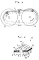
- This type of metal V-belt has been proposed many times from the past and as shown in Fig. 8 is comprised by, for example, an endless belt shaped metal ring 14 and a plurality of metal element members 80 supported along the metal ring member. Further, this metal V-belt transmits power between a drive pulley 11 and a driven pulley 12. Both of these pulleys 11, 12 can variably control the V-channel width and by means of variably controlling the V-channel width of both pulleys, the wrapping radius of the metal V-belt on both pulleys can be changed and the change gear ratio between the drive axle and driven axle changed in infinite steps.
- the metal element members 80 are comprised by a neck portion 7 that joins the gap between a body portion 3 and a head portion 4. Slot portions are formed on both sides of the neck portion 7 which accept the metal ring members 14.
- a saddle surface 1 is formed on the upper portion of the body portion 3 making contact with the metal ring members 14 at the winding regions of the drive pulley and the driven pulley.
- a V-surface 2 is also formed on both sides of the body portion 3 making contact with the V-channel.
- an ear portion 86 is drawn to the left and right on the left and right sides of the head portion 4 (upper portion of slot). This ear portion 86 prevents the metal element members from detaching from the metal ring member.
- an endless ring shaped metal V-belt is formed by means of accepting the metal ring members 14 in a slot formed by the saddle surface and the ear portion and, as shown in Fig. 8, joining the plurality of metal elements.
- an approximate cylindrical shaped convex portion 5 and concave portion (not shown in figure) which are called couplings are formed on the front and rear surfaces of the belt in the travel direction in order to join and position the front and rear metal element members.
- a composition is made in which the linear portion between the two pulleys is positioned continuously by means of joining the convex portion and concave portion of the front and rear surfaces of the metal element members to each other.
- An slanted surface 20 (or recessed surface) is formed on the front surface of the metal element member at the pulley winding region such that is does not interfere with the body portion and a rocking edge 21 that is formed by this slanted surface and the front surface at the pulley winding region functions as a pitch circle pressing on the front and rear metal element members.
- the metal element members will be referred to as members and the metal ring member as a ring.
- the driving force transmits to the driven pulley 12 by means of the elements which are protruding from the drive pulley 11 outlet being positioned by joining the convex portion and concave portion of the front and rear elements which then functions as push type members. Therefore, a compressive force acts on each element at the arcing portion of the belt directed from the drive pulley to the driven pulley without any clearance occurring between the front and rear elements.
- an expansive force is applied to the ring member at the arcing portion of the belt directed from the driven pulley to the drive pulley although no mutual tensile force occurs because each of the elements are gathered together in a plate shaped body.
- a fixed amount of clearance occurs between the elements at this return region.
- This type of metal belt requires each element to be comprised to promote clearance closure movement.
- This clearance closure movement is a movement that functions to join the elements (protruding from the driven pulley) with the elements closest to the drive pulley just before the elements (protruding from the driven pulley) are inserted into the drive pulley in the early stage in the driven pulley outlet arcing region.
- a method for this clearance reducing motion in, for example, Japanese Laid-open Patent Publication No.02-225840(A) in which the composition is such that the center of gravity of transverse elements (elements) are positioned at the outside in the radial direction close to the slanting region of the transverse elements or against the elements thereby maintaining the impact force when the transverse elements protrude from the driven pulley.
- the transverse elements are mutually joined at the return portion without any play and then mutually fit into the drive pulley without any play.
- the method disclosed in Japanese Utility Model Publication No.05-008359(B) is one wherein the elements separated from the pulley at the driven pulley outlet arcing portion pitch at the clearance region as described above and the lower portions of the ear portions of the elements (lower portion of 86 in Fig. 9) strike the outermost periphery (highest portion of 14 in Fig. 9) by point contact.
- the two contact surfaces between the element shoulder (saddle surface 1 in Fig. 9) and the ear of the element are formed in a concentric circular arc shape thereby bringing the ear portion and the ring into surface contact even when the elements pitch to improve the durability.
- the main stated purpose is to create an example wherein the elements which detach the pulley at the driven pulley outlet to possess only the energy that dissipates the play (clearance), the driven pulley protrudes out and transverse elements are combined in front of the drive pulley by means of using transverse elements (elements) which have a center of gravity close to the slanting region of the transverse elements or higher than the slanting region.
- the pitching moment that acts on the elements at the driven pulley outlet is defined as a state in which frictional force in a direction opposite to the travel direction of the belt that acts on the elements at the pulley winding region functions such that pitching occurs at the driven pulley outlet due to the existence of the above-mentioned clearance.
- FIG. 10 This state is described using Fig. 10.
- This figure shows a state in which narrow conventional elements between a ring and a slot receive a pitching moment at the driven pulley outlet region and are leaning forward. Further, the dotted lines in the figure indicate elements which are not pitching.
- the pressing force between the elements at the driven pulley outlet region acts on the area close to the rocking edge 21 on the pitch arc and then a compressive force and a frictional force in the radial direction work together between the elements.
- the transmission of power between the elements and the driven pulley acts on the center 2c of the V-surface 2 of the elements and by means of balancing these two forces, the element positions and state are maintained.
- the gutters at the left and right of the elements close to the pulley outlet can be filled although it does not have any affect on the slanting of the elements mentioned above and consequently, cannot control damage to the ring caused by the lower portion of the ear portion and the outermost peripheral surface of the ring striking each other.
- the object of the present invention is to provide a metal V-belt that has improved durability without impeding the closure movement of the elements at the driven pulley outlet.
- the metal V-belt related to the present invention is comprised such that the clearance in the thickness direction of the belt (for example, slot portion clearance C Y in the embodiment) between the slot portion disposed on the metal element members (for example, element 10 in the embodiment) and the metal element members (for example, ring 14 in the embodiment) is set larger than the clearance in the thickness direction of the belt (for example, coupling portion clearance C NH in the embodiment) of the coupling portion (for example, coupling portion 5 in the embodiment) that is comprised by the concave and convex portions disposed on the front surface and rear surface of the metal element members.
- the clearance in this manner contact between the lower portions of the ear portions and the outermost peripheral surface of the ring can be controlled without impeding the closure movement of the elements at the driven pulley outlet.
- the clearance in the thickness direction of the belt between the slot portion and the metal element members is preferable to set the clearance in the thickness direction of the belt between the slot portion and the metal element members such that the outermost peripheral portion of the metal ring member does not make contact with the metal element member of the upper portion of the slot portion (lower portion of the ear portion 6 in the embodiment) close to the outlet of the driven pulley.
- the action of the above-mentioned pitching moment causes the elements to pitch at the driven pulley outlet resulting in the elements entering a pitched state.
- the clearance between the ring and the slot is small in this pitched state, a state will occur in which the outermost peripheral portion of the ring and the lower portion of the ear portion make contact because of the leaning caused by this pitching action before the closest elements make contact.
- the clearance in the thickness direction of the belt between this ring and slot such that it becomes larger than the clearance in the thickness direction of the belt between the concave and convex portions of the front and rear couplings.
- the convex portion of the coupling makes contact with the concave portion of the closest element in a leaning state while the elements maintain the pitching moment when they are pushed out from the pulley at the driven pulley outlet. This makes it possible to prevent the outermost peripheral portion of the ring and the lower portion of the ear portion from making contact.
- the present invention embodies the metal V-belt by means of setting the clearance in the thickness direction of the belt between the ring and the slot and the clearance in the thickness direction of the belt between the concave and convex portions of the couplings in order that the outermost peripheral portion of the ring does not make contact with the lower portion of the ear portion due to the pitching phenomenon of the elements at the driven pulley outlet when specifying the dimensions of the slot portion of the elements.
- the metal V-belt of the present invention is a belt that can be used in an embodiment identical to the conventional metal V-belt previously shown in Fig. 8 and Fig. 9 and is a belt that has characteristics in the elements which comprise the metal V-belt 13.
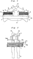
- Fig. 1 shows an element 10 of the present invention.
- the region underneath the lower portion of the ear portion 6 with the hatch lines indicated by D shows differences between a conventional element.
- These types of elements of the present invention can be comprised identical to conventional elements except for clearance C Y in the thickness direction of the belt between the ring 14 of the slot portion S and clearance C NH in the thickness direction of the belt between the concave and convex portions of the couplings.
- the present invention only modifies the dimensions of these two shapes and the composition of the elements can achieve a composition identical to conventional elements (for example, the elements shown in Fig. 9). Consequently, in the following description, identical symbols will be used for portions identical to conventional embodiments which have been described elements up to the present time and their descriptions will be omitted.
- Fig. 2 shows a side view of the element 10 of the present invention.
- This figure shows clearance C Y (hereinafter referred to as simply slot portion clearance) in the thickness direction of the belt between the ring 14 and the slot portion S of the element and radial clearance C NH (hereinafter referred to as simply coupling portion clearance) in the thickness direction of the belt between the concave and convex portions of the couplings.
- Fig. Y hereinafter referred to as simply slot portion clearance
- C NH hereinafter referred to as simply coupling portion clearance
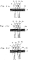
- ring 14 is simplified and indicated by a straight line.
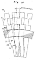
- the element 10 3 on the center right side that has empty space between the elements in each figure is shown as an element pitching due to the pitching action at the pulley outlet and the element 10 4 to the right of element 10 3 is in a driven pulley wound state.
- the two elements 10 1 and 10 2 on the left side away from the empty space in the center are shown in a state in which the belt arcing portion (straight line portion) are released from the pulley.
- Fig. 3 (a) shows when C Y ⁇ C NH and the lean of the element 10 3 at this moment is controlled so the outermost peripheral portion 14a of the ring 14 and the lower portion 6a of the ear portion 6 make contact first. These mutual contact points are indicated by a "()" symbol in each figure.
- Fig. 4 is a conceptual view showing a state when the element 10 receives pitching and pitches at the driven pulley outlet.
- the element 10 pitches with the edge (rocking edge) of the upper side of the V-surface contact portion as a rotation center.
- the angle of the element 10 3 is specified using the relationship between the closest element 10 2 and the ring 14, looking at the explanatory drawing, the angle will have a relationship of ⁇ NH ⁇ ⁇ Y within the usage range of the metal V-belt for the element 10 of the present invention when the leaning angle is ⁇ NH at the moment when the convex and concave portions of the coupling 5 make contact and the leaning angle is ⁇ Y at the moment when the lower portion 6a of the ear portion 6 and the outermost peripheral portion 14a of the ring 14 make contact.
- Fig. 5 shows two examples of the relationship between ⁇ Y and ⁇ NH
- slot portion clearance C Y in the horizontal axis is taken as a rotation angle up to the point of contact in the vertical axis.
- ⁇ Y and ⁇ NH are calculated and plotted in both figures.
- the object of the present invention is to make this possible in this region.
- Fig. 5 shows two types of coupling portion clearance C NH . From a comparison of these two figures, if coupling portion clearance C NH is made larger, the intersecting point O of the above-mentioned ⁇ Y and ⁇ NH moves in the direction where slot portion clearance C Y is larger. Thereupon, the locus of intersecting point O was calculated when the coupling portion clearance C NH was changed.
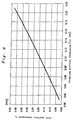
- Fig. 6 shows the results.
- Fig. 6 is line graph in which the coupling portion clearance C NH is shown in the horizontal axis and the slot portion clearance C Y in the vertical axis. In the figure the locus of the above-mentioned intersecting point is plotted.
- the line graph of this figure is a combination of when both the concave and convex portions of the coupling and the ring and the lower portion of the ear portion make contact at the same time. The mutual concave and convex portions of the front and rear coupling make contact sooner than the figure in the upper region and the outermost peripheral portion 14a of the ring and the lower portion 6a of the ear portion do not make contact.
- this region is a region wherein the slot portion clearance is approximately two times more in comparison to the clearance between the concave and convex portions of the coupling.
- Fig. 1 and Fig. 7 show the element 10 of the metal V-belt of the present invention comprised by the method described up to now. At first, as shown in Fig. 1, for this element 10 the region underneath the lower portion of the ear portion 6 with the hatch lines indicated by D is eliminated and the slot portion clearance increased compared to a conventional element.
- the metal V-belt comprised in this manner has sufficient clearance between and the lower portion 6a of the ear portion and the outermost peripheral portion 14a of the ring without the lower portion 6a of the ear portion and the outermost peripheral portion 14a of the ring making contact.
- a metal V-belt comprising an endless metal ring member 14 and a plurality of metal element members 10 supported along said metal ring member wherein the clearance between a slot portion S of the metal element members 10 and the endless metal ring member 14 is set larger than the clearance in the thickness direction of the belt between the concave and convex portions of a coupling portion 5 used for linking disposed on the front and rear surfaces of the metal element members 10.
Landscapes
- Engineering & Computer Science (AREA)
- General Engineering & Computer Science (AREA)
- Mechanical Engineering (AREA)
- Transmissions By Endless Flexible Members (AREA)
- Pulleys (AREA)
Applications Claiming Priority (2)
| Application Number | Priority Date | Filing Date | Title |
|---|---|---|---|
| JP36766198 | 1998-12-24 | ||
| JP10367661A JP2000193041A (ja) | 1998-12-24 | 1998-12-24 | 金属vベルト |
Publications (3)
| Publication Number | Publication Date |
|---|---|
| EP1013964A2 true EP1013964A2 (fr) | 2000-06-28 |
| EP1013964A3 EP1013964A3 (fr) | 2000-07-12 |
| EP1013964B1 EP1013964B1 (fr) | 2003-08-13 |
Family
ID=18489881
Family Applications (1)
| Application Number | Title | Priority Date | Filing Date |
|---|---|---|---|
| EP99125612A Expired - Lifetime EP1013964B1 (fr) | 1998-12-24 | 1999-12-22 | Courroie trapézoidale métallique |
Country Status (4)
| Country | Link |
|---|---|
| US (1) | US6334830B1 (fr) |
| EP (1) | EP1013964B1 (fr) |
| JP (1) | JP2000193041A (fr) |
| DE (1) | DE69910342T2 (fr) |
Cited By (3)
| Publication number | Priority date | Publication date | Assignee | Title |
|---|---|---|---|---|
| EP1236928A1 (fr) * | 2001-02-28 | 2002-09-04 | Toyota Jidosha Kabushiki Kaisha | Courroie de transmission et son procédé de fabrication |
| EP2053269A1 (fr) * | 2007-10-25 | 2009-04-29 | Honda Motor Co., Ltd. | Courroie en V métallique |
| CN109073043A (zh) * | 2016-05-18 | 2018-12-21 | 爱信艾达株式会社 | 传动带 |
Families Citing this family (15)
| Publication number | Priority date | Publication date | Assignee | Title |
|---|---|---|---|---|
| EP1216366B1 (fr) * | 1999-09-15 | 2006-04-19 | Van Doorne's Transmissie B.V. | Courroie |
| JP3669680B2 (ja) * | 2000-01-17 | 2005-07-13 | 本田技研工業株式会社 | 無段変速機用ベルト |
| JP3715166B2 (ja) * | 2000-01-19 | 2005-11-09 | 本田技研工業株式会社 | 無段変速機用ベルト |
| JP3443074B2 (ja) * | 2000-06-02 | 2003-09-02 | 本田技研工業株式会社 | 金属リングの積層方法及びその装置 |
| JP2002048194A (ja) * | 2000-08-03 | 2002-02-15 | Honda Motor Co Ltd | 無段変速機用ベルトの組立方法 |
| ATE459822T1 (de) * | 2000-12-28 | 2010-03-15 | Bosch Transmission Technology | Treibriemen |
| JP3605570B2 (ja) * | 2001-02-13 | 2004-12-22 | 本田技研工業株式会社 | 無段変速機用ベルト |
| US6758778B2 (en) | 2002-02-07 | 2004-07-06 | The Gates Corporation | CVT belt |
| JP4424376B2 (ja) * | 2007-06-06 | 2010-03-03 | トヨタ自動車株式会社 | 伝動ベルト |
| WO2011024236A1 (fr) * | 2009-08-28 | 2011-03-03 | トヨタ自動車株式会社 | Courroie de transmission et procédé de fabrication associé |
| MX369638B (es) * | 2013-06-04 | 2019-11-13 | Honda Motor Co Ltd | Correa de metal para una transmisión contínuamente variable. |
| EP3175937B8 (fr) * | 2015-12-02 | 2021-03-03 | Honda Motor Co., Ltd. | Procédé de fabrication d'élément métallique pour transmission variable continue et élément métallique pour transmission variable en continu |
| WO2018159858A1 (fr) * | 2017-03-03 | 2018-09-07 | アイシン・エィ・ダブリュ株式会社 | Procédé de conception d'élément et courroie de transmission |
| JP6621495B2 (ja) * | 2018-04-03 | 2019-12-18 | 本田技研工業株式会社 | 無段変速機用金属エレメントおよび無段変速機用金属エレメントの製造方法 |
| NL1043501B1 (en) * | 2019-12-10 | 2021-08-31 | Bosch Gmbh Robert | A transverse segment for a drive belt and a drive belt for a continuously variable transmission including the transverse segment and a ring stack |
Citations (3)
| Publication number | Priority date | Publication date | Assignee | Title |
|---|---|---|---|---|
| JPH02225840A (ja) | 1989-01-12 | 1990-09-07 | Van Doornes Transmissie Bv | 駆動ベルトの横断素子 |
| JPH058359B2 (fr) | 1989-11-10 | 1993-02-01 | Kobe Steel Ltd | |
| JPH0610993A (ja) | 1992-03-24 | 1994-01-21 | Van Doornes Transmissie Bv | 駆動ベルト用の横部材 |
Family Cites Families (9)
| Publication number | Priority date | Publication date | Assignee | Title |
|---|---|---|---|---|
| JPS6237645A (ja) | 1985-06-28 | 1987-02-18 | ジユア ベン | 蒸発装置およびこのような蒸発装置を備えた発電ステ−シヨン |
| JPS63280946A (ja) * | 1987-05-13 | 1988-11-17 | Kobe Steel Ltd | 伝導ベルト |
| JPH0830517B2 (ja) * | 1987-10-12 | 1996-03-27 | 日本発条株式会社 | 伝動ベルト用ブロック |
| US4839407A (en) * | 1988-02-08 | 1989-06-13 | Monsanto Company | Particulate polyacetal carboxylate and methods for preparation thereof |
| US5004450A (en) * | 1988-11-04 | 1991-04-02 | Fuji Jukogyo Kabushiki Kaisha | Belt for a continuously variable transmission |
| JP2529017B2 (ja) * | 1990-07-25 | 1996-08-28 | 日産自動車株式会社 | 伝動ベルト |
| JP3065383B2 (ja) | 1991-07-01 | 2000-07-17 | 住友ベークライト株式会社 | フェノール樹脂積層板の製造法 |
| US5439422A (en) * | 1993-05-24 | 1995-08-08 | Van Doorne's Transmissie B.V. | Drive belt |
| JPH10331920A (ja) * | 1997-05-30 | 1998-12-15 | Fuji Heavy Ind Ltd | 無段変速機用金属ベルト |
-
1998
- 1998-12-24 JP JP10367661A patent/JP2000193041A/ja active Pending
-
1999
- 1999-10-26 US US09/426,756 patent/US6334830B1/en not_active Expired - Fee Related
- 1999-12-22 DE DE69910342T patent/DE69910342T2/de not_active Expired - Lifetime
- 1999-12-22 EP EP99125612A patent/EP1013964B1/fr not_active Expired - Lifetime
Patent Citations (3)
| Publication number | Priority date | Publication date | Assignee | Title |
|---|---|---|---|---|
| JPH02225840A (ja) | 1989-01-12 | 1990-09-07 | Van Doornes Transmissie Bv | 駆動ベルトの横断素子 |
| JPH058359B2 (fr) | 1989-11-10 | 1993-02-01 | Kobe Steel Ltd | |
| JPH0610993A (ja) | 1992-03-24 | 1994-01-21 | Van Doornes Transmissie Bv | 駆動ベルト用の横部材 |
Cited By (4)
| Publication number | Priority date | Publication date | Assignee | Title |
|---|---|---|---|---|
| EP1236928A1 (fr) * | 2001-02-28 | 2002-09-04 | Toyota Jidosha Kabushiki Kaisha | Courroie de transmission et son procédé de fabrication |
| EP2053269A1 (fr) * | 2007-10-25 | 2009-04-29 | Honda Motor Co., Ltd. | Courroie en V métallique |
| US7867121B2 (en) | 2007-10-25 | 2011-01-11 | Honda Motor Co., Ltd. | Metal V-belt |
| CN109073043A (zh) * | 2016-05-18 | 2018-12-21 | 爱信艾达株式会社 | 传动带 |
Also Published As
| Publication number | Publication date |
|---|---|
| DE69910342D1 (de) | 2003-09-18 |
| JP2000193041A (ja) | 2000-07-14 |
| DE69910342T2 (de) | 2004-06-24 |
| US6334830B1 (en) | 2002-01-01 |
| EP1013964B1 (fr) | 2003-08-13 |
| EP1013964A3 (fr) | 2000-07-12 |
Similar Documents
| Publication | Publication Date | Title |
|---|---|---|
| EP1013964B1 (fr) | Courroie trapézoidale métallique | |
| US6440023B2 (en) | Metal V-belt | |
| JP3136999B2 (ja) | 無段変速機用vベルト | |
| US6893370B2 (en) | Belt-drive continuously variable transmission | |
| EP1219860A1 (fr) | Courroie de transmission | |
| US8690719B2 (en) | Push type driving belt | |
| US7066858B2 (en) | Belt | |
| CN102348909A (zh) | V形带 | |
| JP3715166B2 (ja) | 無段変速機用ベルト | |
| US6342020B1 (en) | Metal belt | |
| US4666421A (en) | Drive chain belt | |
| US6599212B2 (en) | Belt for continuously variable transmission | |
| JP2004011887A (ja) | 無段変速機用ベルト | |
| JP2000002304A (ja) | チェーン式動力伝達装置 | |
| CN103282690A (zh) | 用于传动带的具有突出的圆锥形凸头的横向元件 | |
| JP2000065153A (ja) | 組立式伝動vベルト | |
| EP1221563A1 (fr) | Courroie de transmission comprenant des éléments transversaux et une bande de support sans fin | |
| US4608036A (en) | Chain V-belt | |
| JP2004176926A (ja) | 駆動ベルト | |
| EP0826901B1 (fr) | Courroie trapézoidale de transmission pour fortes charges | |
| JP3189716B2 (ja) | 無段変速機用vベルト | |
| JP3317217B2 (ja) | 無段変速機用vベルト | |
| JPH0446241A (ja) | サイレントチェーン | |
| JP3690016B2 (ja) | 無段変速機用vベルト | |
| JP2008240958A (ja) | 無段変速機用ベルトおよびベルト式無段変速機 |
Legal Events
| Date | Code | Title | Description |
|---|---|---|---|
| PUAI | Public reference made under article 153(3) epc to a published international application that has entered the european phase |
Free format text: ORIGINAL CODE: 0009012 |
|
| PUAL | Search report despatched |
Free format text: ORIGINAL CODE: 0009013 |
|
| AK | Designated contracting states |
Kind code of ref document: A2 Designated state(s): DE GB NL |
|
| AX | Request for extension of the european patent |
Free format text: AL;LT;LV;MK;RO;SI |
|
| AK | Designated contracting states |
Kind code of ref document: A3 Designated state(s): AT BE CH CY DE DK ES FI FR GB GR IE IT LI LU MC NL PT SE |
|
| AX | Request for extension of the european patent |
Free format text: AL;LT;LV;MK;RO;SI |
|
| 17P | Request for examination filed |
Effective date: 20000809 |
|
| AKX | Designation fees paid |
Free format text: DE GB NL |
|
| GRAH | Despatch of communication of intention to grant a patent |
Free format text: ORIGINAL CODE: EPIDOS IGRA |
|
| GRAH | Despatch of communication of intention to grant a patent |
Free format text: ORIGINAL CODE: EPIDOS IGRA |
|
| GRAA | (expected) grant |
Free format text: ORIGINAL CODE: 0009210 |
|
| AK | Designated contracting states |
Designated state(s): DE GB NL |
|
| REG | Reference to a national code |
Ref country code: GB Ref legal event code: FG4D |
|
| REF | Corresponds to: |
Ref document number: 69910342 Country of ref document: DE Date of ref document: 20030918 Kind code of ref document: P |
|
| PLBE | No opposition filed within time limit |
Free format text: ORIGINAL CODE: 0009261 |
|
| STAA | Information on the status of an ep patent application or granted ep patent |
Free format text: STATUS: NO OPPOSITION FILED WITHIN TIME LIMIT |
|
| 26N | No opposition filed |
Effective date: 20040514 |
|
| PGFP | Annual fee paid to national office [announced via postgrant information from national office to epo] |
Ref country code: NL Payment date: 20091204 Year of fee payment: 11 |
|
| PGFP | Annual fee paid to national office [announced via postgrant information from national office to epo] |
Ref country code: GB Payment date: 20091216 Year of fee payment: 11 |
|
| PGFP | Annual fee paid to national office [announced via postgrant information from national office to epo] |
Ref country code: DE Payment date: 20101215 Year of fee payment: 12 |
|
| REG | Reference to a national code |
Ref country code: NL Ref legal event code: V1 Effective date: 20110701 |
|
| GBPC | Gb: european patent ceased through non-payment of renewal fee |
Effective date: 20101222 |
|
| PG25 | Lapsed in a contracting state [announced via postgrant information from national office to epo] |
Ref country code: GB Free format text: LAPSE BECAUSE OF NON-PAYMENT OF DUE FEES Effective date: 20101222 |
|
| PG25 | Lapsed in a contracting state [announced via postgrant information from national office to epo] |
Ref country code: NL Free format text: LAPSE BECAUSE OF NON-PAYMENT OF DUE FEES Effective date: 20110701 |
|
| REG | Reference to a national code |
Ref country code: DE Ref legal event code: R119 Ref document number: 69910342 Country of ref document: DE Effective date: 20120703 |
|
| PG25 | Lapsed in a contracting state [announced via postgrant information from national office to epo] |
Ref country code: DE Free format text: LAPSE BECAUSE OF NON-PAYMENT OF DUE FEES Effective date: 20120703 |